Page is loading ...

RuggedNet
®
10GPoE+/Mi
Managed 6 and 10 Port
PoE/PoE+ 10Gigabit Ethernet Switch
Quick Start Guide
38 Tesla, Irvine, CA 92618 USA
Phone: (949) 250-6510; Fax: (949) 250-6514
General and Copyright Notice
This publication is protected by U.S. and international copyright laws. All rights
reserved. The whole or any part of this publication may not be reproduced, stored
in a retrieval system, translated, transcribed, or transmitted, in any form, or by
any means, manual, electric, electronic, electromagnetic, mechanical, chemical,
optical or otherwise, without prior explicit written permission of Omnitron Systems
Technology, Inc.
The following trademarks are owned by Omnitron Systems Technology, Inc.:
FlexPoint
TM
, FlexSwitch
TM
, iConverter
®
, miConverter
TM
, NetOutlook
®
, OmniLight
®
,
OmniConverter
®
, RuggedNet
®
, Omnitron Systems Technology, Inc.
TM
, OST
TM
and
the Omnitron logo.
All other company or product names may be trademarks of their respective owners.
The information contained in this publication is subject to change without notice.
Omnitron Systems Technology, Inc. is not responsible for any inadvertent errors.
Warranty
This product is warranted to the original purchaser (Buyer) against defects in
material and workmanship for a period of two (2) years from the date of shipment.
A ve (5) year warranty may be obtained by the original purchaser by registering
this product at www.omnitron-systems.com/support within ninety (90) days from the
date of shipment. During the warranty period, Omnitron will, at its option, repair or
replace a product which is proven to be defective with the same product or with a
product with at least the same functionality.
For warranty service, the product must be sent to an Omnitron designated facility,
at Buyer’s expense. Omnitron will pay the shipping charge to return the product
to Buyer’s designated US address using Omnitron’s standard shipping method.
Limitation of Warranty
The foregoing warranty shall not apply to product malfunctions resulting from
improper or inadequate use and/or maintenance of the equipment by Buyer, Buyer-
supplied equipment, Buyer-supplied interfacing, unauthorized modications or
tampering with equipment (including removal of equipment cover by personnel not
specically authorized and certied by Omnitron), or misuse, or operating outside
the environmental specication of the product (including but not limited to voltage,
ambient temperature, radiation, unusual dust, etc.), or improper site preparation
or maintenance.
No other warranty is expressed or implied. Omnitron specically disclaims the implied
warranties of merchantability and tness for any particular purpose.
The remedies provided herein are the Buyer’s sole and exclusive remedies. Omnitron
shall not be liable for any direct, indirect, special, incidental, or consequential
damages, whether based on contract, tort, or any legal theory.
Page 2

Environmental Notices
The equipment covered by this manual must be disposed of or recycled in
accordance with the Waste Electrical and Electronic Equipment Directive (WEEE
Directive) of the European Community directive 2012/19/EU on waste electrical and
electronic equipment (WEEE) which, together with the RoHS Directive 2015/863/
EU, for electrical and electronic equipment sold in the EU after July 2019. Such
disposal must follow national legislation for IT and Telecommunication equipment
in accordance with the WEEE directive: (a) Do not dispose waste equipment with
unsorted municipal and household waste. (b) Collect equipment waste separately.
(c) Return equipment using collection method agreed with Omnitron.
The equipment is marked with the WEEE symbol shown to indicate that it
must be collected separately from other types of waste. In case of small items the
symbol may be printed only on the packaging or in the user manual. If you have
questions regarding the correct disposal of equipment go to www.omniton-systems.
com/support or e-mail to Omnitron at [email protected].
Safety Warnings and Cautions
ATTENTION: Observe precautions for handling electrostatic discharge
sensitive devices.
WARNING: Potential damage to equipment and personal injury.
WARNING: Risk of electrical shock.
WARNING: Hot surface.
RuggedNet
®
10GPoE+/Mi
Quick Start Guide
Product Overview
The RuggedNet 10GPoE+/Mi is a ruggedized managed PoE and PoE+ industrial
Ethernet switch that features
two 1/10G uplink ports and four or eight 10/100/1000
RJ-45 copper Power Sourcing Power-over-Ethernet user ports.
The mode of operation can be congured using easily accessible DIP-switches or
using Web, Telnet, SSH, SNMPv1/v2c/v3 or Serial Console management interfaces.
These management interfaces provide access to ltering and security options, such
as, broadcast storm prevention, IGMP, IEEE 802.1x, RADIUS, TACACS+ and Access
Control Lists. Email event notication and alarm reporting is provided using Simple
Mail Transfer Protocol. To access the user manuals for the Web Interface (3xxxUM-02x
Web Interface OmniConverter RuggedNet Switches) and Command Line Interface
(3xxxUM-01x Command Line Interface OmniConverter RuggedNet Switches),
access the product pages at: www.omnitron-systems.com.
RuggedNet 10GPoE+/Mi 6 and 10 Ports
The 10GPoE+/Mi is a Power Sourcing Equipment (PSE) that provides up to 30W
PoE+ (IEEE 802.3at) per user port and supports frame sizes up to 10,240 bytes.
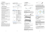
Front Panel
The front of the module provides access to the management (serial console), RJ-45
user ports and uplink ports.
The front of the module provides access to the RJ-45 PoE and uplink ports.
RJ-45 PoE, Uplinks and Fixed-Fiber Ports
The RJ-45 PoE Ethernet user port supports 10BASE-T, 100BASE-TX and
1000BASE-T protocols, auto-negotiation, auto MDI/MDI-X crossover and can be
manually forced to a specic speed and duplex mode.
The module supports two 1/10G SFP/SFP+ transceiver uplink ports.
The SFP/SFP+ ports support SERDES 10GBASE-X and 1000BASE-X copper and
ber transceivers, and SGMII 10/100/1000BASE-T copper transceivers.
Page 3
Page 4

Page 5
Front Panel Layout
Serial Console Port
To congure the module using the serial port, attach a DB-9 serial (RS-232)
equipped computer with terminal emulation software such as Procomm or Putty
to the serial port on the module using a RJ-45 to DB-9 serial cable (not included).
Some computers do not come with DB-9 serial port connectors and may require a
USB-to-serial port adapter.
The port is a standard RS-232 asynchronous serial interface. The serial ports is
congured for 57,600bps, 1 stop, 8 data, parity none. The serial adapter cable
pin-outs are illustrated below.
Standard RJ-45 to DB-9 serial cable pin-out
Reset Button
A reset button is available on the front of the switch to restore the switch to factory
default values. Press and hold the reset button for more than 5 seconds to restore
the switch to factory default values.
Installation Procedure
1) Congure DIP-switches
2) Installing the Module
3) Apply DC Power
4) Connect Cables
5) Verify Operation
Page 6
1) Congure DIP-switches
The DIP-switches are located on the top of the module. The DIP-switches are used
to congure modes of operation, networking features and PoE reset.
DIP-switch Bank Locations
The table below provides a description of each DIP-switch position and function.
Switch Position Legend Function
SW1
LEFT Single Switch
Mode of Operation
RIGHT Dual Switch
SW2
LEFT Switch
RIGHT Directed Switch
SW3
LEFT Off
Uplink Redundancy
RIGHT Link Protection
SW4
LEFT No Return
RIGHT F1 Return
SW5
LEFT MAC Learning MAC Learning Enabled (factory default)
RIGHT Off MAC Learning Disabled
SW6
LEFT Off Pause Disabled (factory default)
RIGHT Pause Pause Enabled
SW7
LEFT L2CP Tunnel L2CP Tunnel (factory default)
RIGHT Discard L2CP Tunnel Discard
SW8
LEFT Off PoE Reset Disabled (factory default)
RIGHT PoE Reset PoE Reset Enabled
DIP-switch Denitions
SW1 and SW2: Mode of Operation
The modules support Switch, Directed Switch and Dual Device modes.
The modes are described with MAC learning enabled. When MAC learning is
disabled, unicast packets are forwarded to all ports.

Page 7
SW1 SW2 Function
LEFT LEFT Switch Mode (factory default)
LEFT RIGHT Directed Switch Mode
RIGHT LEFT Dual Device Mode - Switch Mode
RIGHT RIGHT Dual Device Mode - Directed Switch Mode
Modes of Operation
Switch Mode
When congured for Switch Mode (factory default), the module operates as a
standard layer 2 switch. Data ow will follow MAC address mapping.
Directed Switch Mode
When congured for Directed Switch Mode, trafc from all the PoE RJ-45 user
ports is only forwarded to the uplink port F1, preventing the broadcast trafc from
ooding other network ports. The data trafc on the additional uplink port (F2) is
also forwarded to port F1. Incoming trafc from F1 follows MAC address mapping.
Directed Switch Mode Dual Uplink Port
When models with two uplink ports are congured for Directed Switch Mode and
Uplink Redundancy (per DIP-switches 3 and 4), trafc is forwarded to both the
primary and secondary uplink ports. The secondary port will block all trafc while
the primary port is active. When the primary port goes down, the secondary port
will be active and all trafc will be forwarded out the secondary port (F2).
Directed Switch Mode with Uplink Redundancy
Page 8
Dual Device Mode
When congured for Dual Device Mode, the module is congured as two logically
independent Layer 2 switches. On models with 4 RJ-45 user ports, Port F1 is
associated with ports P1 and P2 and Port F2 is associated with ports P3 and P4.
On models with 8 RJ-45 user ports, Port F1 is associated with ports P1 - P4 and
Port F2 is associated with ports P5 - P8. Data ow will follow MAC address mapping.
Dual Device Mode
When models with 4 RJ-45 user ports are congured for Dual Device Mode and
Directed Switch Mode, the trafc from ports P1 and P2 is only forwarded to uplink
port F1 and ports P3 and P4 are only forwarded to uplink port F2. When models with
8 RJ-45 user ports are congured for Dual Device Mode and Directed Switch Mode,
the trafc from ports P1 - P4 is only forwarded to uplink port F1 and ports P5 - P8
are only forwarded to uplink port F2. This prevents broadcast trafc from ooding
other network ports. Incoming trafc from F1 and F2 follows MAC address mapping.
Dual Device with Directed Switch Mode
SW3 and SW4: Uplink Redundancy
The modes are described with MAC learning enabled. When MAC learning is
disabled, the module will send data to all ports.
SW3 SW4 Function
LEFT LEFT Switch Mode (factory default)
LEFT RIGHT Switch Mode (factory default)
RIGHT LEFT Redundant Mode - no return to primary (F1)
RIGHT RIGHT Redundant Mode - return to primary (F1)
Uplink Redundancy

Page 9
When congured for Uplink Redundant Mode “no return to primary”, the uplink
ports operate as redundant links. A fault on the primary Port F1, will cause a fail
over to the secondary Port F2 within 50msec. Port F1 will become the secondary
port once the failure condition has been restored because “no return to primary”
has been selected.
Redundant Uplink
When congured for Uplink Redundant Mode “return to primary’, a fault on the
primary Port F1, will cause a fail over to the secondary Port F2 within 50msec.
The module will return to the primary Port F1 after the failure condition has been
restored for 6 seconds.
SW5: MAC Learning - “MAC Learning/Off”
When this DIP-switch is in the LEFT “MAC Learning” position (factory default), all
ports on the module will learn the source MAC address of each received packet and
store the address so packets destined for the stored addresses can be forwarded
to the appropriate port on the module. When the DIP-switch is in the RIGHT “Off”
position, learning is turned off and all received unicast packets are forwarded to
all ports.
SW6: Pause - “Pause Off/On”
Setting the DIP-switch to the LEFT “Pause Off” position (factory default) congures
the module to advertise no Pause capability on all ports. Setting this DIP-switch
to the RIGHT “On” position congures the module to advertise Symmetrical and
Asymmetrical Pause capability to all ports.
SW7: L2CP - “L2CP Tunnel/Discard”
When this DIP-switch is in the LEFT “L2CP Tunnel” position (factory default), all
L2CP frames will be tunneled through the module. When this DIP-switch is in the
RIGHT “Discard” position, all L2CP frames will be discarded.
SW8: PSE Reset - “Off/PoE Reset”
The module can be congured to disable (reset) the PoE output power for 5 seconds
after a loss of receive link on any uplink port. This feature is typically used to allow
a PD to re-initialize after a failure on the incoming uplink.
When this DIP-switch is in the LEFT “Off” position (factory default), PoE output power
does not reset on a loss of receive link on any uplink port. When this DIP-switch is
in the RIGHT “PoE Reset” position, the module will disable PoE output power for 5
seconds following a loss of receive link on any uplink port.
Page 10
When uplink redundancy is enabled, the loss of link on either F1 or F2 will not cause
the PD to be re-initialized even though the PSE Reset is enabled. The PD will be
re-initialized on a loss of receive link on both uplink ports.
When Dual Device Mode is enabled, the loss of receive link on a uplink port will
re-initialize the PDs associated with that uplink port. On models with 4 RJ-45 user
ports, ports P1 and P2 will drop PoE power when a loss of receive link on F1 is
detected and ports P3 and P4 will drop PoE power when a loss of receive link on
F2 is detected. On models with 8 RJ-45 user ports, P1 - P4 will drop PoE power
when a loss of receive link on F1 is detected and ports P5 - P8 will drop PoE power
when a loss of receive link on F2 is detected.
2) Installing the Module
The module can be wall or rack mounted using the optional Wall Mount Plate
(8260-3). Refer to the Wall Mount Plate user manual (040-08260-301x) for the
proper installation guidelines.
Wall Mounting
The wall mounting height of the module should be less than or equal to 2 meters
(6.6 feet) from the oor. Use the four mounting holes on the module to secure the
module to the wall. The module can accommodate #6 screws (not included).
Installation of the module should be such that the air ow in the front, back, side
and top vents of the switch are not compromised or restricted.
The accessory cables should have their own strain relief and do not pull down on
the module.
Rack Mounting
The module can be rack mounted using the optional Rack Mount Shelf (8260-0).
Refer to the Rack Mount Shelf user manual (040-08260-001x) for the proper
installation guidelines.
Follow the same guidelines above when rack mounting the module.
3) Apply DC Power
This module is intended for installation in restricted access areas. (“Les matériels
sont destinés à être installés dans des EMPLACEMENTS À ACCÈS RESTREINT”).
A restricted access area can be accessed only through the use of a special key, or
other means of security.
The over current protection for connection with centralized DC shall be provided in
the building installation, and shall be a UL listed circuit breaker rated 20 Amps, and
installed per the National Electrical Code, ANSI/NFPA-70.
The 6 Port 10GPoE+/Mi requires +48 to +57VDC inclusive of tolerance (2.33A
@ 56VDC max rated power). The 10 Port 10GPoE+/Mi requires +46 to +57VDC
inclusive of tolerance (4.49A @ 56VDC max rated power). See specication table
for specic model requirements.
Appropriate overloading protection should be provided on the DC power source
outlets utilized.

Page 11 Page 12
Top View with DC Power Connector
WARNING: OnlyaDC power source that complies with
safety extra low voltage (SELV) requirements can be
connected to the DC-input power supply.
WARNING REGARDING EARTHING GROUND:
o
o
o
o
This equipment shall be connected to the DC supply
system earthing electrode conductor or to a bonding
jumper from an earthing terminal bar or bus to which the
DC supply system earthing electrode is connected.
This equipment shall be located in the same immediate
area (such as adjacent cabinets) as any other equipment
that has a connection between the earthed conductor of
the same DC supply circuit and the earthing conductor,
and also the point of earthing of the DC system. The DC
system shall not be earthed elsewhere.
The DC supply source is to be located within the same
premises as this equipment.
There shall be no switching or disconnecting devices in
the earthed circuit conductor between the DC source and
the earthing electrode conductor.
Locate the DC circuit breaker of the external power source, and switch the circuit
breaker to the OFF position.
Prepare a power cable using a three conductor insulated wire (not supplied) with
12AWG to 14AWG thickness. Cut the power cable to the length required.
Strip approximately 3/8 of an inch of insulation from the power cable wires.
Connect the ground wire to the grounding screws on the back of the module.
Ground Screw Location
Connect the power cables to the module by fastening the stripped ends to the DC
power connector.
Power Connections
Power Options
WARNING: The positive lead of the power source must be connected to the
“+” terminal on the module and the negative lead of the power source to the
“-“ terminal on the module as shown above.
WARNING: Note the wire colors used in making the positive, negative and
ground connections. Use the same color assignment for the connection at
the circuit breaker.
Connect the power wires to the circuit breaker and switch the circuit breaker ON.
If any modules are installed, the Power LED(s) will indicate the presence of power.
During the installation, ensure that the ground potentials are maintained throughout
the system connections. This includes but not limited to the power source ground
and any shielded cabling grounds.
NEVER ATTEMPT TO OPEN THE CHASSIS OR
SERVICE THE POWER SUPPLY. OPENING THE
CHASSIS MAY CAUSE SERIOUS INJURYOR DEATH.
THERE ARE NO USER REPLACEABLE OR
SERVICEABLE PARTS IN THIS UNIT.
WARNING!!!
Make sure to disconnect both power connectors and the ground cables before
removing the equipment.
4) Connect Cables
a. Insert the SFP/SFP+ transceiver into the SFP receptacle on the front of
the module (see the SFP Data Sheet 091-17000-001 for supported Gigabit
transceivers or 091-17400-001 for supported 10G transceivers).
NOTE: The release latch of the SFP ber transceiver must be in the closed
(up) position before insertion.

Page 13 Page 14
b. Connect an appropriate multimode or single-mode ber cable to the ber port
on the front of the module. It is important to ensure that the transmit (TX) is
attached to the receive side of the transceiver at the other end and the receive
(RX) is attached to the transmit side. When using single-ber (SF) models, the
TX wavelength must match the RX wavelength at the other end and the RX
wavelength must match the TX wavelength at the other end.
c. Connect the Ethernet 10/100/1000 RJ-45 port using a Category 5 or better
cable to an external 10BASE-T, 100BASE-TX or 1000BASE-T Ethernet device.
Description IEEE 802.3af PoE IEEE 802.3at PoE+
Power Supply Voltage Range 46.0 to 57.0 VDC 51.0 to 57.0 VDC
Voltage Range at PSE port Output 44.0 to 56.0 VDC 50.0 to 56.0 VDC
Maximum Power from PoE/PSE port 15.4 watts 30 watts
Minimum Voltage at PoE/PD port input* 37.0 VDC 42.5 VDC
Minimum Power at PoE/PD port* 12.95 watts 25.5 watts
* at 100 meters using Cat5
PoE and PoE+ Requirements
5) Verify Operation
Verify the module is operational by viewing the LED indicators.
Power
LED Indicators
Legend Indicator Description
Pwr
OFF Unit not powered
Green - ON Unit powered
Amber - ON Over temperature condition
Power LED Indicators
Uplink
LED Indicators
Legend Indicator Description
1000
(Link)
OFF Port not linked
Green - ON Port linked at the speed indicated by the Speed LED
Green - Blinking at 10Hz Port is transmitting or receiving data
Green - Blinking at 1Hz Port in redundant secondary mode
10G
(Speed)
OFF Port not linked
Amber - Blinking at 1Hz Port not linked and receiving remote fault or FEFI
Green - single blink Port linked at 10M, 100M or 1G
Green - two blinks Port linked at 2.5G
Green - three blinks Port linked at 5G
Green - four blinks Port linked at 10G
SFP/Uplink Ports LED Indicators LED Indicators
RJ-45 User Ports
LED Indicators
Legend Indicator Description
100
4P Models
8P Models
OFF No link
Green - ON Port linked at 100Mbps
Green - Blinking at 10Hz Port data activity at 100Mbps
Amber -ON Port linked at 100Mbps Half-duplex
Amber - Blinking at 10Hz Port data activity at 100Mbps Half-duplex
1000
4P Models
8P Models
OFF No link
Green - ON Port linked at 1000Mbps
Green - Blinking at 10Hz Port data activity at 1000Mbps
Amber -ON Port linked at 1000Mbps Half-duplex
Amber - Blinking at 10Hz Port data activity at 1000Mbps Half-duplex
10
4P Models
8P Models
OFF No link
Green - ON Port linked at 10Mbps
Green - Blinking at 10Hz Port data activity at 10Mbps
Amber -ON Port linked at 10Mbps Half-duplex
Amber - Blinking at 10Hz Port data activity at 10Mbps Half-duplex
RJ-45 LED Indicators
PoE/PSE (next to the RJ-45 Ports)
LED Indicators
Legend Indicator Description
PoE/PSE
OFF Port PSE inactive
Amber - ON Port PSE inactive - exceeding the power source
Green - single blink Powered by 802.3af PoE 15W
Green - two blinks Powered by 802.3at PoE 30W
PoE/PSE LED Indicators

Page 15 Page 16
Specications
Description
RuggedNet
®
10GPoE+/Mi
10/100/1000BASE-T with 1G or 10Gigabit Uplinks
Managed 6 or 10 Port 10Gigabit Ethernet Switch with PoE+
Standard Compliances
IEEE 802.3, IEEE 802.1Q, IEEE 802.1ad, IEEE 802.1ab, IEEE 802.1w,
IEEE 802.1ax, RFC 5424, RFC 4541, IEC 624339-2, SMTP, SNTP,
RADIUS, TACACS+, IEEE 802.1x,
IEEE 802.3af (15.40 watts), IEEE 802.3at (30 watts)
Environmental
REACH, RoHS and WEEE
Management
Web, Telnet, SSH, Serial Console, SNMPv1/v2c/v3
PoE Modes
IEEE Alternate A (Alt A)
Frame Size Up to 10,240 bytes
Port Types
Copper: 10/100/1000BASE-T (RJ-45)
SFP/SFP+: 10GBASE-X Fiber Transceivers
10GBASE-T Copper Transceivers
1000BASE-X Fiber and Copper Transceivers
10/100/1000BASE-T SGMII Copper Transceivers
Serial: RJ-45 (RS-232)
Cable Types
Copper: EIA/TIA 568A/B, Cat 5 UTP and higher
Fiber: Multimode: 50/125, 62.5/125µm
Single-mode: 9/125µm
Serial: Category 3 and higher
DC Power Requirements
4 RJ-45 Ports:
+46 to +57VDC; inclusive of
tolerances
2.33A @ 56VDC
2 Pin Terminal (non-isolated)
8 RJ-45 Ports
+46 to +57VDC; inclusive of
tolerances
4.49A @ 56VDC
2 Pin Terminal (non-isolated)
Dimensions (W x D x H) 1.5” x 5.5” x 5.5” (38.1 mm x 139.7 mm x 139.7 mm)
Weight
4 RJ-45 Ports:
1.70 lb. (772 grams)
8 RJ-45 Ports:
1.77 lb. (803 grams)
Operating Temperature
Extended: -40 to 75°C
Storage: -40 to 80°C
Humidity 5 to 95% (non-condensing)
Altitude -100m to 4,000m (operational)
MTBF (hours) 263,000
Warranty 5 year product warranty with 24/7/365 free Technical Support
Regulatory Compliances
(Pending)
Safety: UL 60950-1, UL-62368-1, IEC 60950-1:2005+A1:2009,
IEC 62368:2014/A11:2017, EN 60950-1:2006+A11:
2009+A1:2010+A12:2011+A2:2013, CAN/CSA C22.2 No.
60950-1, CAN/CSA C22.2 No. 62368-1-14, CE Mark
EMC: EN 55032/EN 55024 CE Emissions/Immunity,
IEC 61000-6-4 Industrial Emissions,
IEC 61000-6-2 Industrial Immunity
EMI: CISPR 32, FCC 47 Part 15 Subpart B Class A
EMS: IEC 61000-4-2 ESD: Contact: 4 kV; Air: 8 kV,
IEC 61000-4-3 RS: 80 MHz to 1 GHz: 10V/m,
IEC 61000-4-4 EFT: Power: 2 kV; Signal: 1 kV,
IEC 61000-4-5 Surge: Power: 2 kV; Signal: 1 kV,
IEC 61000-4-6 CS: Signal: 10 V,
IEC 61000-4-8 (Magnetic Field),
IEC 61000-4-11 (General Immunity in Industrial
Environments )
IP Rating: IP40 Protection
Customer Support Information
If you encounter problems while installing this product, contact Omnitron Technical
Support:
Phone: (949) 250-6510
Fax: (949) 250-6514
Address: Omnitron Systems Technology, Inc.
38 Tesla
Irvine, CA 92618, USA
Email: [email protected]
URL: www.omnitron-systems.com
040-09582-001A 7/20
/