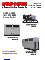
Winpower DR600 Operating instructions
- Category
- Power generators
- Type
- Operating instructions


Page i
TABLE OF CONTENTS
INTRODUCTION i
GUIDE TO PRODUCT SAFETY 1
BASIC INFORMATION 2
Description 2
DGC-2020 Engine Control Layout 3
DGC-2020 Display Operations 5
RECEIVING THE GENERATOR 6
Unpacking the unit 6
Lifting the unit 7
ENGINE GENERATOR INSTALLATION 7
Installation 6
Engine Generator Set Mounting 8
Fuel Installation 8
Lubrication 8
Coolant 8
Battery Installation 9
Battery Charger/Block Heater Wiring 9
Mounting The Transfer Switch 10
AC ELECTRICAL CONNECTIONS 10
DC ELECTRICAL CONNECTIONS 12
INITIAL START-UP 13
EXERCISER CLOCK 14
TROUBLESHOOTING INFORMATION 14
APPENDIX DIRECTORY 15
Appendixes 16-29
12 MONTH WARRANTY 30
PROPER USE AND INSTALLATION
You must be sure your new engine generator set is:
* Properly serviced before starting
* Operated in a well ventilated area
* Properly exhausted and gases safely dispersed
* Wired by a qualified electrician
* Operated only for its designed purposes
* Used only by operators who understand its operation
* Properly maintained
SAVE THESE INSTRUCTIONS
This manual contains important instructions that
should be followed during installation and maintenance
of the generator and batteries.
Read and understand all instructions in the manual
before starting and operating the generator set.
USING THIS MANUAL
Congratulations on your choice of a Winpower genera-
tor set. You have selected a high-quality, precision-engi-
neered generator set designed and tested to give you years
of satisfactory standby service.
To get the best performance from your new engine
generator set, it is important that you carefully read and
follow the operating instructions in this manual.
Should you experience a problem please follow the
“Things To Check” near the end of this manual. The
warranty listed in this manual describes what you can
expect from WINPOWER should you need service assis-
tance in the future.
COPY YOUR MODEL AND SERIAL NUMBER HERE
No other WINPOWER generator has the same serial
number as yours. It is important that you record the num-
ber and other vital information here. If you should ever need
to contact us on this unit it will help us to respond to your
needs faster.
MODEL_____________________________________
SERIAL NUMBER____________________________
'M" Spec. __________________________________
PURCHASE DATE____________________________
DEALER____________________________________

60708-142 Page 1 8122-00
2. FIRE HAZARD - Deisel fuel presents a hazard of possible
explosion and/or fire.
a. Do not smoke or use open flame near the generator
set.
b. Keep a fire extinguisher nearby and know its proper use.
Fire extinguishers rated ABC by NFPA are appropriate.
3. DEADLY EXHAUST GAS - Exhaust fumes from any diesel
engine contain carbon monoxide, an invisible, odorless
and deadly gas that must be mixed with fresh air.
a. Operate only in well ventilated areas.
b. Never operate indoors.
c. Never operate the unit in such a way as to allow exhaust
gases to seep back into closed rooms (i.e. through
windows, walls or floors).
4. NOISE HAZARD - Excessive noise is not only tiring, but
continual exposure can lead to loss of hearing.
a. Use hearing protection equipment when working
around this equipment for long periods of time.
b. Keep your neighbors in mind when permanently install-
ing this equipment.
5. CLEANLINESS - Keep the generator and surrounding area
clean.
a. Remove all grease, ice, snow or materials that create
slippery conditions around the unit.
b. Remove any rags or other material that could create
potential fire hazards.
c. Carefully wipe up any fuel or oil spills before starting the
unit.
d. Never allow leaves or other flammable material to build
up around the engine exhaust area.
6. SERVICING EQUIPMENT - All service, including the
installation or replacement of service parts, should be
performed only by a qualified technician.
a. Use only factory approved repair parts.
b. Do not work on this equipment when fatigued.
c. Never remove the protective guards, cover, or recep-
tacle panels while the engine is running.
d. Use extreme caution when working on electrical compo-
nents. High output voltages from this equipment can
cause serious injury or death.
e. Always avoid hot mufflers, exhaust manifolds, and
engine parts. They all can cause severe burns instantly.
f. Installing a generator set is not a “do-it-yourself” project.
Consult a qualified, licensed electrician or contractor.
The installation must comply with all national, state, and
local codes.
g. Always make sure unit is disabled before placing your
hands anywhere near the fan, belts, alternator or water
hoses.
IMPORTANT SAFETY
INSTRUCTIONS
SAVE THESE INSTRUCTION
This manual contains important instructions that
should be followed during installation and maintenance
of the generator and batteries.
Read and understand all instructions in the manual
before starting and operating the generator set.
This engine generator set has been designed and manufac-
tured to allow safe, reliable performance. Poor maintenance,
improper or careless use can result in potential deadly hazards;
from electrical shock, exhaust gas asphyxiation, or fire. Please
read all safety instructions carefully before installation or use.
Keep these instructions handy for future reference. Take special
note and follow all warnings on the unit labels and in the manuals.
ANSI SAFETY DEFINITIONS
************************************************************
DANGER:
DANGER indicates an imminently hazardous situation which, if
not avoided, will result in death or serious injury. This signal word
is to be limited to the most extreme situations.
***********************************************************
************************************************************
WARNING:
WARNING indicates a potentially hazardous situation which, if
not avoided, could result in death or serious injury.
***********************************************************
***********************************************************
CAUTION:
CAUTION indicates a potentially hazardous situation which, if not
avoided, may result in minor or moderate injury. It may also be
used to alert against unsafe practices.
************************************************************
NOTE:
CAUTION is also used on the unit labels and in this manual to
indicate a situation that could result in serious damage or
destruction of the equipment and possible personal injury.
1. ELECTRIC SHOCK - The output voltage present in this
equipment can cause a fatal electric shock. This equipment
must be operated by a responsible person.
a. Do not allow anyone to operate the generator without
proper instruction.
b. Guard against electric shock.
c. Avoid contact with live terminals or receptacles.
d. Use extreme care if operating this unit in rain or snow.
e. Use only three-prong grounded receptacles and
extension cords.
f. Be sure the unit is properly grounded to an external
ground rod driven into the earth.

Page 2
8122-00 60708-142
MODEL NUMBERING SYSTEM
BUILD YOUR GENSET REQUIREMENT FROM
THE BOTTOM OF THE PAGE TO THE TOP
FUEL TYPE D = DIESEL
G = GASEOUS
STARTING METHOD
R - REMOTE STARTING
GASEOUS FUEL TYPE
N = NATURAL GAS
P = LIQUID PROPANE VAPOR L = L/P LIQUID WITHDRAWL
NOT USED WITH DIESEL FUEL
G R N 20 I 4 - A H M T
GENERATOR OUTPUT IN KILOWATTS WITH STANDBY
KILOWATTS
ENGINE MANUFACTURE
V = VOLVO I = ISUZU (10 & 20 kW)
I = IVECO (ALL OTHERS) G = GM
D = DEUTZ N = NG ENGINES
NUMBER OF POLES ON THE GENERATOR
4 POLES STANDARD
BASE UNIT - OPTIONS SEPARATOR
VOLTAGE
A = SINGLE PHASE 120/240
D = THREE PHASE 120/208 J = THREE PHASE 120/240
L = THREE PHASE 277/480
HOUSING TYPE
H = WEATHER HOUSING (WEATHER-PAK)
S = SOUND ATTENUATED/WEATHER PROTECTIVE (SOUND-PAK)
* = NO HOUSING
FUEL TANK SIZE
M = MEDUIM L = LARGES = SMALL * = NONE SEE CURRENT PRICE SHEET
TO DETERMINE CAPACITY
TRAILER OPTION IF PRESENT UNIT IS MOUNTED ON A
TRAILER WITH FUEL TANK FUEL. TANK SIZES SHOWN BY
PREVOUIS LETTER (SMALL AND MEDUIM FUEL TANKS ONLY)
TESTING POLICY:
Before any generator is shipped from the factory, it is fully
checked for performance. The generator is loaded to its full
capacity, and the voltage, current, and frequency are carefully
checked.
Rated output of generators is based on engineering tests of
typical units, and is subject to, and limited by, the temperature,
altitude, fuel, and other conditions specified by the manufacturer
of the applicable engines.
INTRODUCTION AND
DESCRIPTION
PRODUCT DESCRIPTION:
This engine-generator set is designed for unattended remote start
operation. It can be operated as part of a fully automatic standby
power system or independently as a local start unit in a prime power
system. The engine-generator set is fully tested at the factory prior
to shipment to insure proper operation of each individual component
as well as the total system's performance and reliability.
The engine generator set consists of a multi-cylinder, liquid cooled
engine nominally operating at 1800 rpm. The generator frequency
regulation is maintained by the engine governor to within +/- 1.5 hertz
(cps), from no load to rated load for standard mechanical governors
and to within +/- .5 hertz or better for units equipped with an electronic
governor. The generator is a single bearing, direct drive, rotating
field design. The generator is connected to the engine flywheel via
flexible drive disks. The Generator Set is skid mounted with isolation
mounts between the engine and base on all units.
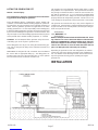
Unit Orientation Note: All references used in this manual for unit
familiarization, access and component locations on the Generator
Set are oriented from a TOP (plan) VIEW with engine at the FRONT
and generator to the REAR.
WINPOWER uses a common junction box for all customer control
and power connections (both AC output and DC control). The
common electrical junction box is always on the left side at the
generator end of the machine.
A customer supplied 12 (or 24) Volt battery is required to complete
the installation. See appendix 1, to identify the voltage, size and CCA
(Cold Cranking Amp) requirements for your specific unit.
The engine is controlled and Generator Set operation is monitored
for safe operation by a programmable microprocessor based Elec-
tronic Engine Control Module (ECM) with an LCD digital display. The
Generator Set ECM control is mounted on a vertical pedestal on the
right side of the generator. (Except for the DR10 & DR20 which are
mounted on top the generator housing) The ECM is programmed
with a cycle cranking sequence - 3 cycles of 15 seconds on / 15
seconds off, and a 5 minute cool down delay. The cool down delay
can be changed in the field from 0 to 30 minutes by your dealer. Other
features, timing cycles, set points and signal output capabilities are
possible. Consult factory for procedure and passwords.
** NOTICE **
These units will automatically transfer if a power outage occurs
while running in an exercise mode.
MODEL NUMBER STRUCTURE:
The WINPOWER alpha-numerical numbering system consists of a
base model designation, followed by an options section, separated
by a dash mark. The base component of the model numbering
system identifies an engine type, engine starting method, fuel type,
kilowatt rating, engine manufacturer, and number of generator poles.
Following the separation dash mark is the voltage connection and
optional installed equipment. Options include features like weather
enclosures (housing), base mounted fuel tank sizes, and trailer
options.
Please note that some features or packages, such as NFPA level
I & II, do not have an indication place in this numbering system.
They are issued and built with an M-Spec (i.e. M-10372) number
which can be found on the WINPOWER data tag. When the M-
Spec is present, supplemental inserts will accompany this
standard manual providing information about the special equip-
ment and features installed. The standard model numbering key
that can be used along with the data tag information and/or M-
spec supplements to determine the generator sets ratings and
specifications

60708-142 Page 3 8122-00
The rated power of each engine-generator is limited by the
temperature, altitude and all other ambient conditions specified
by the engine manufacturer. Engine power will decrease 3-1/2%
for each 1000 ft. above sea level, and will decrease an additional
1% for each 10 degrees Fahrenheit above 60 degrees Fahren-
heit. Units should not be operated in ambient temperature greater
than 125 degrees Fahrenheit.
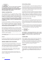
GENERATOR:
WINPOWER Generators Sets use totally brushless, AVR (Auto-
Voltage Regulator) controlled broad-range generator ends. The
generator converts rotational mechanical energy into electrical
energy. Standard WINPOWER units are equipped with genera-
tors manufactured by Stamford/Newage. Each generator ‘end’
has its own data tag. The unique serial number is stamped on the
data plate and into the upper section of the mounting adapter of
the generator frame. The data label is affixed to the main frame
of the generator on the lower left side, similar to the sample
shown.
ENGINE CONTROL PANEL LAYOUT
SPECIFICATIONS
GENERATOR SET:
Every WINPOWER Generator Set has its own unique identity data
plate. This data plate identifies the complete unit model number,
the system serial number and has links to the individual compo-
nents that form the generator set in our factory records. Several of
the major components also have their own individual identity plates
providing additional information to document build data for warranty
and replacement parts.
Be sure to have the main WINPOWER unit data plate information
recorded inside the front cover of this manual for future reference
and for identification whenever requesting field or factory technical
assistance. Sample data plate is shown for reference. Primary fields
needed for assistance are complete model number, serial number
and especially the M-Spec number. The M-Spec number (if pro-
vided) is recorded in the ‘TYPE NO.’ block on the Lower Right of the
plate. See the appendixs in the back of this manual for individual
units specifications and wiring diagram references.
ENGINE:
Each engine has a nameplate on it that gives the specific engine
model number, build specification and the serial number for the
engine. See the technical data pages in the back of this manual
for individual engine specifications, fuel consumptions and wiring
diagram references.
This manual covers specific operation of the combined engine
generator set. Refer to engine operating and maintenance
instructions for specific instruction on the care and maintenance
of the engine. Oil and fuel requirements along with maintenance
schedules and engine warranty information are provided by the
individual engine manufactures.
** CAUTION **
EQUIPMENT DAMAGE - Be sure to check the engine oil level
frequently as specified in the engine manual.
The engine manufacturer has established an excellent worldwide
engine service organization; engine service is available from a
nearby authorized dealer or distributor; check the Yellow Pages
of the telephone directory under “engines,” or ask the dealer from
whom you purchased the power plant.
Typical Winpower Nameplate

Page 4
8122-00 60708-142
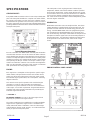
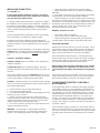
A - DGC-2020 Digital Gen-Set Control. See Explanation
below.
B - DC Control Circuit Fuse. The 10 amp DC Circuit Fuse
protects the 12 volt circuits and engine wiring harness against
faults in wiring or control equipment. The fuse also prevents a
discharge of the battery due to a circuit fault. (Replacement
AGC-10A-250V)
C - DGC-2020 Fuse. This 3 amp DC fuse protects the DGC-
2020 printed circuit board. (Replacement AGC-3A-250V)
D - Emergency Stop Switch - When depressed this switch will
disconnect all the 12 volt power to the DGC-2020 shutting the
engine down. The lamp in the emergency stop switch will light
up when the switch is depressed showing that the power to the
panel has been disconnected.
E - Voltage Adjustment Rheostat. This 2 watt 1k ohm
rheostat is used to fine tune your output voltage from the
generator. If for some reason the voltage should get way out of
range and you can not get it back with the adjustment range on
the rheostat, there is a course voltage adjustment pot on the
voltage regulator
ENGINE CONTROL MODULE (DGC-2020)
Note: A CD was shipped with this unit to support the DGC-
2020. The CD contains the complete operators manual and
the software to reprogram the DGC-2020 if the need should
ever arise. Please store it in a safe place.
The DGC-2020 Digital Generator Set Controller provides
integrated engine-generator set control, protection, and
metering in a single package. Microprocessor based technol-
ogy allows for exact measurement, set point adjustment, and
timing functions. Front panel controls and indicators enable
quick and simple DGC-2020 operation. Basler Electric communica-
tion software (BESTCOMSPlus) allows units to be easily custom-
ized for each application. A wide temperature-range liquid crystal
display (LCD) with backlighting can be viewed under a variety of
ambient light and temperature conditions.
FEATURES
DGC-2020 Digital Generator Set Controllers have the following
features:
• Local and Remote Generator Control
• Engine and Generator Protection
• Programmable Analog Engine Senders
• Programmable Logic
• Automatic Transfer Switch Control (Mains Failure)
• Integrated RS485 interface
• Auto Synchronizing
FUNCTIONS
DGC-2020 Digital Generator Set Controllers perform the following
functions:
Generator Protection and Metering
Generator protection guards against over voltage, under voltage,
under frequency, and over frequency. Over current and phase
imbalance protection is available as an option at the time of
manufacture. Each generator protection function has an adjustable
pickup and time delay setting. Metered generator parameters
include voltage, current, real power (watts), apparent power (VA),
and power factor (PF).
Engine Protection and Metering
Engine protection features include oil pressure and coolant tem-
perature monitoring, over crank protection, ECU specific protection
elements, and diagnostic reporting.
ENGINE
CONTROL
MODULE
DGC-2020

60708-142 Page 5 8122-00
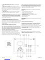
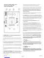
move downward through the menu levels and the left-arrow
button is pressed to move upward. Within a level, the up-arrow
and down-arrow buttons are used to move among items within
the menu level. Pressing the down-arrow button moves to items
lower in the list. Pressing the up-arrow button moves to items
higher in the list. During a settings editing session, the up- and
down-arrow buttons are used to raise and lower the value of the
selected setting.
L - Edit Push-button. Pressing this button starts an editing
session and enables changes to the DGC-2020 settings. At the
conclusion of an editing session, the Edit push-button is pressed
again to save the setting changes.
DISPLAY OPERATION
The front panel display is used to make settings changes and
display metering values. Refer to call-outs J, K, and L in text and
illustration for information on changing settings through the front
panel and navigating through the Metering screens. When the
unit is first powered up, the clock may need to be reset. Editing
the clock provides familiarity with the edit process. All program-
ming changes from the front panel are accessed through the edit
key to begin and exit the internal microprocessor program.
Log-in and Permissions
To Log-in, navigate to the SETTINGS, ENTER PASSWORD
screen and press the Edit key. Use the Up/Down arrow keys to
scroll through the characters. Use the Left/Right arrow keys to
enter more characters. The Owner operator password is OP.
Once the password has been entered, press the Edit key to Log-
in. See the key stroke sequence listed below to access the
control and enter the edit mode. A LOGOUT selection now
appears in the list of SETTINGS. To logout, navigate to SET-
TINGS, LOGOUT and press the Edit key. The LOGOUT selection
is removed from the SETTINGS list.
Sequence for setting (or resetting) the system clock -
1) Press ‘K’ (right key) for initial set or ‘K’ (left to back up, up /
down) to choose menu item and time/date element to be
changed.
2) Press ‘L’ (Edit) to access change mode to enter Password -
OP as follows:
2a -Press K (up) to select O
2b -Press K (right) to move cursor
2c -Press K (up) to select P
2d -Press L (Edit) to begin change mode
3) Press ‘K’ (up or down) to choose year
4) Press ‘L’ (Edit) to enter year
5) Press ‘K’ (down) to select month mode
6) Press ‘L’ (Edit) to access month change
7) Press ‘K’ (up or down) to choose month
8) Press ‘L’ (Edit) to enter month
9) Repeat sequence 5 through 8 for day, minute, second and
DST (Daylight Saving Time).
To finish clock setting, process - Press ‘K’ (left).
Metered engine parameters include oil pressure, coolant
temperature, battery voltage, speed, engine load, coolant level
(from ECU), ECU specific parameters, and run-time statistics.
All metering functions are displayed on the liquid crystal display.
The front panel display begins with the SUMMARY SCREEN.
Pressing the Right arrow key will open the MAIN MENU screen.
The MAIN MENU screen consists of METERING and SETTINGS
Summary Screen
Summary screen can be set to standard or scrolling. When set to
standard, only the following are displayed:
• Generator Voltage
• Generator Amperage
• Generator Phase
• Generator Frequency
• Engine Oil Pressure
• Engine Coolant Temperature
• Engine Battery Voltage
A - Liquid Crystal Display. The backlit, 64 by 128 pixel LCD
serves as the local information source for metering, alarms, pre-
alarms and protective functions. Display operation is maintained
at -20°C. An optional LCD heater would maintain display opera-
tion at -40°C.
B - Not in Auto Indicator. This red LED lights when the DGC-
2020 is not operating in Auto mode.
C - Alarm Indicator. This red LED lights continuously during
alarm conditions and flashes during pre-alarm conditions.
D - Supplying Load Indicator. This green LED lights when the
generator current is greater than EPS threshold current.
E - Alarm Silence Push-button. Pressing this button opens the
relay output programmed as the horn output.
F - Lamp Test Push-button. Pressing this button tests the DGC-
2020 indicators by exercising all LCD pixels and lighting all LEDs.
G - Auto Push-button and Mode Indicator. Pressing the Auto
button places the DGC-2020 in Auto mode. The green Auto mode
LED lights when Auto mode is active.
H - Off Push-button and Mode Indicator. Pressing this button
places the DGC-2020 in Off mode. The red Off mode LED lights
when the DGC-2020 is in Off mode.
I - Run Push-button and Mode Indicator. Pressing this button
places the DGC-2020 in Run mode. The green Run mode LED
lights when Run mode is active.
J - Reset Push-button. This button is pressed to cancel a
settings editing session and discard any settings changes. When
pressed, this button also resets the Breaker Management Pre-
Alarms
K - Arrow Push-buttons. These four buttons are used to
navigate through the front panel display menus and modify
settings. The left- and right-arrow buttons are used to navigate
through the menu levels. The right arrow button is pressed to

Page 6
8122-00 60708-142
The microprocessor is still in the General Settings Edit mode.
Pressing ‘K’ (left) a second time exits the Edit mode and allows
full access to the View Only mode for all control settings and
current status. Any items to be changed are accessed by
pressing ‘K’ (up/down/right or left) to select, ‘L’ (Edit) to change
and ‘K’ (left) to exit.
Communication
Standard DGC-2020 communication features include a standard
USB port and SAE J1939 interface. Optional communication
features include a dial-out modem and RS-485 communication port.
The USB communication port can be used with BESTCOMSPlus
software to quickly configure a DGC-2020 with the desired settings
or retrieve metering values and event log records. The CANBus
interface provides high-speed communication between the DGC-
2020 and the engine control unit (ECU) on an electronically con-
trolled engine. This interface provides access to oil pressure, cool-
ant temperature, and engine speed data by reading these param-
eters directly from the ECU. When available, engine diagnostic data
can also be accessed. The CANBus interface supports the follow-
ing protocols:
• SAE J1939 Protocol - Oil pressure, coolant temperature, and
engine speed data are received from the ECU. In addition, DTCs
(Diagnostic Trouble Codes) help diagnose any engine or related
failures. The engine DTCs are displayed on the front panel of the
DGC-2020 and may be obtained using BESTCOMSPlus software.
• MTU/MDEC Protocol - A DGC-2020 connected to a generator
Set equipped with an MTU MDEC receives Oil pressure, coolant
temperature, and engine speed data from the engine controller, along
with various alarms and pre-alarms that are MDEC specific. In ad-
dition, the DGC-2020 tracks and displays the active fault codes is-
sued by the MDEC ECU.
Optional - Dial-Out Modem One of two optional, dial-out modems
(a US version or international version) enables remote control,
monitoring, and setting of the DGC-2020. When an alarm or pre-
alarm condition occurs, the DGC-2020 can dial up to four telephone
numbers, in sequence, until an answer is received and the condi-
tion is annunciated.
Optional - RS-485 Port The RS-485 communication port uses the
Modbus communication protocol and enables remote control and
monitoring of the DGC-2020 over a polled network
.RECEIVING THE GENERATOR
The generator set will generally be shipped by a commercial ‘com-
mon freight carrier’. Large and bulky units are often shipped on a
dedicated or specially contracted ‘Flat-Bed’ truck. The means of
shipment is determined in consultation between the WINPOWER
Sales and Shipping staff and the customer. Routing is determined
by the bulk, size, and a means available to unload the generator at
the receiving end. WINPOWER recommends units that are shipped
by common carrier be delivered to a commercial dock to allow the
Generator Set to be unloaded in a safe, efficient manner and to
minimize handling damage to the unit.
Locate the packing slip on the side of the crate or request it from
the truck driver. When receiving the unit take special care in exam-
ining the unit for damage during shipment. Avoid signing for the
equipment until a full visual assessment and inventory have been
made. Verify that you have received the right equipment and the
proper amount by matching up the equipment to the packing list.
Larger units may ship with the fuel tank and muffler removed. Verify
that those components are undamaged and removed from the truck
prior to their release.
The keys for doors of the enclosed generators sets are typically
attached to lifting eye on the base of the machine. These keys are
matched to all the doors on the generator set housing.
UNPACKING INSTRUCTIONS:
When unpacking the generator set, be sure to inspect it carefully for
freight loss or damage. If loss or damage is noted at the time of
delivery, require that the person making the delivery make note of
the loss or damage on the freight bill, or affix his signature under the
consignee’s memo of the loss or damage. Contact the carrier for
claim procedures.
When loss or damage is noted after delivery, segregate the dam-
aged material, and contact the carrier for claim procedures.
“Concealed Damage” is understood to mean damage to the con-
tents of a package which is not in evidence at the time of delivery by
the carrier, but which is discovered later. The carrier or carriers are
responsible for merchandise lost or damaged in transit. The title to
goods rests with the consignee when generators are shipped fob
factory, and only the consignee can legally file a claim.
***** CAUTION ****
EQUIPMENT DAMAGE - These units are shipped with oil,
and a 50/50 mix of coolant. Be sure to check all fluid
levels before operating. See engine manufacturer’s
instruction manual for recommended oil requirements
before initial starting.
UNPACKING:
(Not recommended until the unit is on-site)
1. Carefully remove the crate.
2. After inspecting the engine-generator for external physical
damage, locate and check the following items packed with
the unit.
a. Owner’s operators manual.
b. Engine manufacturer’s instruction manual.
c. Battery hold-down brackets & hardware.
d. Unit components or accessory items shipped loose
for on-site installation.
e. Optional accessories (i.e. remote annunciator)
3. Remove main frame hold down bolts.
4. Unit can now be lifted from shipping rails.

60708-142 Page 7 8122-00
LIFTING THE GENERATOR SET
NOTICE - Personal Injury
To prevent injury to persons or equipment, observe the follow-
ing guidelines when lifting the generator:
Due to the different designs, configurations, options, weights, site
conditions, and available material handling equipment, specific lift-
ing instructions are not provided for each individual generator set
model. General guidelines provided are applicable to the entire
standby generator line. It is the responsibility of the installing party
to follow the lifting equipment’s operators manual to prevent injury
to personnel and damage to the generator. Smaller Generator Sets
may not require use of overhead lifting equipment and may be placed
on the pad with basic material handling equipment, i.e. a forklift.
CAUTION: - Do not attempt to lift the generator set by the means
of the lifting eyes on the engine or generator end.
These lifting points are only for use during the manufacturing pro-
cess and are designed for lifting of the individual Generator Set
component.
WINPOWER has designed all of its Generators Sets to be lifted at
the corners with an appropriate lifting rig. The lifting points are
located on the side rails of the generator base or on the optional
base mounted fuel tank of a Diesel Generator Set.
The generator set can be lifted with properly rated chains or cables
along with the use of spreader bars. The spreader bars should be
long enough so that the lift cables or chains do not come into con-
tact with the generator set. Use of commercially available lifting
fixtures may also be used. Always be sure that the equipment is
properly rated for the weight of the generator. Failure to do so can
cause damage to the generator, injury to personnel or even death.
The generator set and fuel tank may or may not be shipped as a
complete unit. If the fuel tank is shipped separate from the genera-
tor, place the tank on the cement pad first, and then place the gen-
erator on top of the fuel tank.
***************
***** WARNING ****
***************
NEVER - attempt to lift the fuel tank while filled with fuel. Slosh-
ing of the fuel can cause a shift in the balance of the fuel tank,
making for a DANGEROUS, unbalanced lifting load. If the gen-
erator was shipped on the fuel tank, use the lifting points lo-
cated on the fuel tank to move the entire Generator Set into
place. DO NOT place fuel in the tank prior to lifting.
Depending on generator set size and configuration, the exhaust
system may ‘ship loose’ with the generator set for installation on
site. The muffler and its attaching brackets must be mounted on
top of the generator housing prior to operating the engine
generator set.
INSTALLATION

Page 8
8122-00 60708-142
***************
***** WARNING ****
***************
PERSONAL INJURY - Before proceeding with the installation,
be sure the DGC-2020 is in the "stop" position. Before
proceeding with the installation, be sure the Generator MLCB
(Main Line Circuit Breaker) is in the ‘OFF’ position and the
unit starting battery is disconnected.
GENERAL INFORMATION
These engine/generator sets are generally supplied as weather
enclosed packages for quick installation on an outdoor concrete
pad. They are also available as open skid mounted units for indoor
installation in a building or protective enclosure supplied by the
installer. The factory weather enclosures are available as standard
or acoustical housing intended for outdoor installation only. Factory
weather enclosed units are not intended to be used indoors and
no support is available to assist in re-engineering finished
packaged units.
All versions must be bolted to a solid base for proper operation. A
properly designed concrete pad is necessary for stationary opera-
tion. A substantial DOT certified trailer is required for mobile appli-
cations. Consult a qualified, licensed electrician or contractor to
install and wire this Generator Set. The installation must comply
with all national, state, and local codes.
Before beginning the installation process, recheck the voltage,
phase and amperage rating of the Generator Set and ATS (Auto-
matic Transfer Switch). Be certain they can handle the intended load
and are compatible with the entrance voltage, phase and current
ratings. Plans for installation should be prepared with proper
attention to mechanical and electrical engineering detail to assure a
satisfactory system installation.
The information in this manual is offered only as a guide to finalizing
your installation plans.
NOTICE
For full service switching of the entire load, the ATS must be ‘SE’
(Service Entrance) rated or must have a properly rated fusible
disconnect installed before the ATS to protect the contacts.
.
ENGINE GENERATOR SET MOUNTING
The unit’s main frame must be bolted solidly to a 4 to 6 inch thick
cement pad. The engine-generator is mounted on a sub-frame
which is attached with special shock mounts to the main frame.
This allows the engine-generator free movement without affecting
the control panel which is mounted on the main frame.
Do not shock mount the main frame. Engine vibration will be
transmitted to the control panel causing erroneous start/stop
cycles and premature control failure.
The unit should be mounted to allow for ample working room
around it. A general rule to follow is five (5) feet of clearance on
all sides. (Code NFPA 37)
FUEL INSTALLATION
The fuel supply should be as close to the engine as possible. This
will reduce the installation cost of fuel runs and minimize line losses.
The diesel fuel supply should be no more than 3 feet below the fuel
inlet on the pump. If your fuel supply is lower than three feet you may
have to install an additional lift pump to bring the fuel up to the
mechanical fuel pump on the engine.
The information in this manual is offered to assist you in providing the
proper fuel for your engine. However, this information is only pro-
vided to inform you of the engine’s requirements and assist in
making you aware of the decisions you must make. In no case
should the instructions or information provided be interpreted to
conflict with any local, state or national codes. If in doubt, always
consult your local fire marshal or fuel supplier.
INSTALLING THE FUEL LINE
Engine generator sets are properly adjusted before they leave the
factory. Connecting a fuel supply with adequate supply volume is
critical to reliable operation. Diesel units with optional base mounted
fuel tanks are pre-plumbed to the mechanical fuel pump on the
engine.
Open skid mounted Diesel units are often supplied with capped inlet
and return lines. The use of a suitable customer supplied flexible fuel
line is essential between the engine and fuel supply to provide a
vibration break between your fuel supply and the engine.
***************
***** WARNING ****
***************
FIRE DANGER - Connecting rigid fuel line (i.e. steel or copper
line) directly to the inlet fuel filter or fuel pump may cause the
fuel line to crack during operation creating a serious fire
hazard.
LUBRICATION
Before starting the engine, check the oil level in the crankcase. If
it is low, refill to the full mark with the proper weight/grade of oil as
recommended by the engine manufacturer’s maintenance
instructions. The necessity of using the correct oil, and keeping
the crankcase full cannot be over emphasized. Failure to use the
proper oil and keep the crankcase properly filled will cause
excessive engine wear and shorten its useful life.
COOLANT
Before starting the engine, check the coolant level in the radiator.
If it is low, refill as specified in the engine manufacturer’s mainte-
nance instructions. The radiator should be filled to about 1 inch
below the filler neck. For additional information on engine coolant
requirements see engine manufacturer’s maintenance instruc-
tions.

60708-142 Page 9 8122-00
INSTALLING THE BATTERY
**** CAUTION ****
In the following battery installation procedure, check to be
sure the DGC-2020 is in the “stop” position. This should be
your last step before initial start-up.
A customer supplied twelve-volt battery is required to complete
the installation; 24 volt systems require 2 batteries. Installation of
the highest CCA rated battery, within the correct BCI group, will
increase cold weather starting performance. Gel batteries should
not be used with the battery tender installed in the generator
enclosure.
See the specification listing in appendix 1 for the correct battery
size and minimum CCA rating for the different models.
Installation and servicing of batteries must be performed or
supervised only by personnel knowledgeable of batteries and the
required precautions. Keep unauthorized personnel away from
batteries.
When installing or replacing batteries, use the proper group/size
starting battery. The battery should be a Maintenance Free lead
acid design. Deep cycle batteries will not work for this applica-
tion.
CAUTION – PERSONAL DANGER
CAUTION - NEVER dispose of a battery in a fire. The battery is
capable of exploding.
CAUTION -DO NOT open or mutilate the battery. Released
electrolyte is known to be harmful to the skin and eyes and to be
very toxic.
These engine generator sets are all NEGATIVE ground. Be very
careful not to connect the battery in reverse polarity, as this may
short circuit the battery charging system on the engine.
CAUTION – A battery presents a risk of electrical shock and high
short circuit current. The following precautions must be observed
when working with batteries:
1. Remove watches, rings and other metal objects.
2. Use tools with insulated handles.
3. Check both the battery cable ends and the battery posts to be
sure they are free of corrosion.
3. Always connect the battery positive cable first and then
connect the battery negative cable. When removing the battery
cables from the battery reverse the procedure, disconnect the
negative cable first and then the positive cable.
4. Be sure all connections are tight and coat the terminals and
cable ends with dialectic grease.
WARNING – The electrolyte is a diluted sulfuric acid that is
harmful to the skin and eyes. It is electrically conductive and
corrosive. The following precautions must always be taken:
* Always wear full eye protection and protective clothing
* Where electrolyte contacts the skin, wash off immediately
with water
* If electrolyte contacts the eyes, flush thoroughly and immedi-
ately with water and seek immediate medical attention
* Spilled electrolyte is to be washed down with an acid neutral-
izing agent. A common practice is to use a solution of one pound
of bicarbonate of soda (baking soda) to one gallon of water. The
bicarbonate of soda solution is to be added until the evidence of
reaction, foaming, has ceased. The resulting liquid is to be
flushed with water and the area dried.
DANGER – Explosive Fire Risk
* Never smoke when near batteries
* Do not cause a flame or spark in the battery area
* Always discharge static electricity from your body before
touching batteries by first touching a grounded metal surface
SERVICING BATTERIES
Batteries used on these units may, over time, lose water. This is
especially true if you are using a trickle charger to maintain your
battery. When refilling the battery with water use only distilled
water. Tap water will shorten the service life of the battery.
Never fill the battery above the fill line. Over filling above the
upper level line may cause the electrolyte to overflow, resulting in
corrosion to the engine or nearby parts. Immediately wash off
any spilled electrolyte following the procedure above.
NOTE: Always make sure that a new battery is fully charged
before installing it on a generator set. Failure to do so can
cause damage to the engine control module in the generator
set.
All connections must be clean and tight. Check the electrolyte
(fluid) in the battery periodically to be sure it is above the plates.
Never allow the battery to remain in a discharged condition.
CONNECTING THE BATTERY CHARGER &
BLOCKHEATER
A two-stage battery tender is provided for all standby generators.
These battery chargers can vary depending on what model you
have purchased and what the original specifications call for. For
unit operating at 12 volts D.C. the standard charger is a battery
tender that charges at a rate of 750 mA until the battery is fully
charged and then automatically switches to a 13.2 VDC float
charger. The charger has an indicator light on it, red indicates it
is charging, and green indicates it is in the storage mode (float
charge). This charger is mounted on the left hand side of the AC
connection cabinet.
All 24 volt battery chargers and option 12 volt chargers will have
either a cord on them that you can plug into the receptacle on the
side of the connection box or depending on size they may require
hard wiring in the terminal block in the bottom of the connection
box.

Page 10
8122-00 60708-142
** NOTICE **
The trickle charger is not intended to recharge a battery
which has become completely discharged. It is designed to
produce just enough current to maintain a fully charged
battery.
The battery tender receptacle is to be powered by a GFCI circuit
and installed in accordance with the United States National
Electric Code. It is suggested that this circuit be fused for 20 -30
amps, depending on blockheater requirements. Then both the
battery charger and the block heater can be connected to the
same circuit. A 120 volt duplex receptacle is mounted on the
generator along the side circuit breaker panel, for a 20 amp
circuit and terminal blocks are provided for heavier circuits.
The engine blockheater installed on this unit should also be
plugged in this receptacle. The block heater is thermostatically
controlled and when plugged in will maintain the engine coolant
temperature between 100 and 120 degrees F.
MOUNTING THE AUTOMATIC
TRANSFER SWITCH (A.T.S.)
*************
***** WARNING *****
*************
FIRE HAZARD - All wiring must be done by a licensed
electrician, and must conform to the National Electrical Code
and comply with all state and local codes and regulations.
Check with the local authorities before proceeding!
INSTALLATION NOTES
Because of the many different types of service, feeder, and
distribution equipment, no specific wiring instructions can be
provided. It is recommended that only copper wire be used. In
all cases it is essential that while the load is connected to the
generator, there can be absolutely no feedback from the genera-
tor to the power line or the power line to the generator. When
properly installed, the normal A.T.S. Control and safety systems
will eliminate all paths for feedback.
To wire the automatic transfer switch into the existing wiring, first
determine which circuits will be on the emergency load circuit. If
the entire load is to be transferred, the transfer switch can be
wired in directly after the watt-hour meter and the service en-
trance, providing the service entrance ampere rating is within the
transfer switch’s rated capability.
If only specific circuits are to be powered under emergency power
failure conditions, an additional distribution panel designated
“emergency distribution panel” must be installed.
All selected emergency circuits are removed from main distribu-
tion panels and installed in the emergency distribution panel. The
A.T.S. is then installed between the main panel and the emer-
gency distribution panel. Suggested circuits: freezer, refrigerator,
furnace, emergency lights, sump pump, emergency outlet circuits,
etc. Total running load must not exceed generator rating.
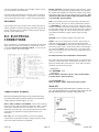
A.C. ELECTRICAL
CONNECTIONS
NOTICE - CLASS 1 WIRING METHODS ARE TO BE USED FOR
ALL FIELD WIRING CONNECTIONS TO TERMINALS OF A
CLASS 2 CIRCUIT
Note: This symbol always indicates ground where
shown.
All wiring must be completed in accordance with the Nation
Electric Code as well as any state or local codes.
You must pay particular attention to wire size requirement for the
amperage of service you are dealing with. Appendix "2" provides
you guidance on wire sizing based on both wire type and amper-
age. Wire amperage's have been derated for 40o C ambient
temperatures operation.
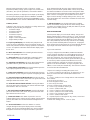
CUSTOMER CONNECTION BOX FOR
BOTH AC & DC CONNECTION
10 kW THROUGH 125 kW

60708-142 Page 11 8122-00
A - Neutral Lugs, These neutral lugs are isolated from ground
and provided for you to connect your neutral wire from the
transfer switch to the generator.
The 1200 amp terminal block lugs on the 300 to 600 kW will
handle wire sizes #3/0 to 600 MCM and should be torqued to 28
ft. lbs.
The 1000 amp terminal block lugs on the 130 kW to 250 kW will
handle wire sizes #3/0 to 500 MCM and should be torqued to 28
ft. lbs. (Rated for 900 AMP for AL)
The 400 amp terminal block lugs on the 65 & 90 kW will handle
wire sizes #1 AWG to 400 MCM and should be torqued to 300 in.
lbs.
The 225 amp terminal block lugs on the 20 kW to 45 kW will
accommodate #4 AWG to 300 MCM and should be torqued to
250 in. lbs.
B - Generator Circuit Breaker, This circuit breaker provides
overload protection for the generator. Your power feeds from the
transfer switch will connect to the bottom lugs on the circuit
breaker. The generator power feeds have already been wired
into the upper lugs.
Please refer to the circuit breaker installed on your unit for
breaker lug capacities and proper torque specifications.
To select the proper conductor size between the Generator and
the ATS, first look your model up in Table 1 of Appendix "A" for
your generator amperage. Then refer to Appendix "2" for guid-
ance on wire sizing based on both wire type and amperage.
Wire amperages have been derated for 40o C ambient tem-
peratures operation.
For additional information on wire sizing refer to table 310-16 of
the National Electrical Code ANSI/NFPA 70.
C - Ground Lug, These ground lugs are bonded to ground and
are provided for you to connect your ground wire from the transfer
switch to. The lugs on the 65 kW and larger will handle wire sizes
#6 AWG to 300 MCM and should be torqued to 21 ft. lbs. The
lugs on the 20 &45 kW will accommodate #10 AWG to 2/0 AWG
and should be torqued to 200 in. lbs.
D - Customer DC Connection terminal block. - See DC
CONNECTIONS
E - 120 VOLT GFCI CIRCUIT TERMINAL BLOCK - These
terminals are rated for 85 amps and will handle wire sizes #4
AWG to #18 AWG. They should be torqued to 16 in. lbs. This
circuit must be fed from a fused circuit in the distribution panel
and provides power for the blockheater and the battery charger.
F - 120 VOLT/20 AMP DUPLEX RECEPTACLE, This conve-
nience receptacle is used on the small units to plug in both the
small float charger as well as the blockheater. On some the units
with the larger block heater you will have to wire directly into the
terminal block.
G - This lug is provided on the neutral terminal block to allow you
to run a neutral to ground lead if you are using the generator in a
stand alone application. This would be an application where
there is not distribution panel and no other ground to neutral
bond in the wiring system. If a grounding wire is attached here
remove the floating neutral label in the panel. This will not be
used when you are wiring a generator and transfer switch
into an existing power system.
*************
***** WARNING *****
*************
A main line circuit breaker has been provided inside the
generator housing. During all wiring installations make sure
the breaker is in the OFF position and the generator opera-
tion switch is in the OFF position.
*************
***** WARNING *****
*************
EQUIPMENT DAMAGE - When installing a Three Phase 240
volt system be sure you know which lead is the high voltage
"wild" leg (208Volt line to neutral). The generator normally
carries the high voltage on the G2 lead.
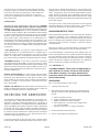
CUSTOMER CONNECTION BOX FOR
BOTH AC & DC CONNECTION
150 kW THROUGH 400 kW

Page 12
8122-00 60708-142
All wires should be installed in rigid or flexible conduit. (Knock-
outs are provided in the control box).
See the manual shipped with the Automatic Transfer Switch for
connection locations in the switch. Connections in each switch
will vary depending on the type of switch and the manufacturer.
GROUNDING
A grounding lug has been provided on the engine generator set
and the generator set must be properly grounded to good earth
ground. Generally a 8 foot copper rod driven into the earth will
provide a proper earth ground.
D.C. ELECTRICAL
CONNECTIONS
All DC connections are completed in the small box located in the
upper left hand corner of the customer connection box. All DC
connection must be run in separate conduit. You can not mix
AC and DC leads in the same conduit.
ESTOP- & ESTOP+ - Remote Emergency Stop terminals. These
two terminals are shipped with a jumper installed. If your applica-
tion requires the installation of a Remote Emergency Stop switch,
remove the jumper and wire your switch to these terminals. This
unit will not start and run without either the jumper installed
or a remote N/C switch installed.
RUN - This terminal provides a 12 volt positive signal any time
the unit is running. Wiring a 12 volt relay between this terminal
and GROUND will provide you a relay closure anytime the unit is
running. In addition, some stand alone battery chargers require a
12 volt positive signal to the charger anytime the unit is running to
turn the battery charger off. This is done to prevent an interfer-
ence between the battery charger and the engine charging
system.
GROUND - This is a battery negative connection point.
START - This is your remote start connection. When using an
Automatic Transfer Switch a connection through the transfer
switch back to GROUND activates the auto start sequence in the
DGC-2020 engine control. These leads must be routed though a
dry contact that closes on line power failure. This remote start
feature can be driven by any relay closure for applications where
an A.T.S. is not used.
DC Interconnections to the Automatic Transfer Switch
Two control wires are required between the A.T.S. panel and the
generator control terminal box. Depending on the distance, 14 to
16 gauge stranded wire should be used. These wires should be
labeled S1 (ground) and S23 (start).
*************
***** WARNING *****
*************
Be sure Engine Generator is in the "OFF" position before
you make any DC interconnections.
*******CAUTION******
Never run the AC and DC wiring in the same conduit.
Zenith ATS
The terminal markings in the Zenith ATS are marked “X1” and
“X2”. The wire labeled “Start 1” is routed to start contact "X1” and
the wire labeled “Start 23” is routed to start contact “X2”
CONNECTION BOX TERMINALS
Wire size requirements for each of the connections may
vary but terminal lugs should be used for all connections.
Torque spec for terminal lugs is 9 in. lbs.
485 B+, 485 B-, POWER + and POWER - are the interconnection
leads for a Basler "RDP-110 REMOTE DISPLAY PANEL" (remote
annunciator). Minimum wire size is 20 AWG, you can use two
twisted pair up to 4000 feet. (This feature meets the annunciation
requirements in applications requiring NFPA110 level one
protection.)
B.C. FAIL - This is an input terminal, used to send a battery
charger failure signal from the battery charger to the DGC-2020
and to the remote annunicator is applicable.
X1 X2

60708-142 Page 13 8122-00
ASCO 165 UL SWITCH
Your DC connection points in the ASCO 165 ATS are
terminals “4” and “5 on the interface terminal block.
ASCO 300 UL SWITCH
Your DC connection points in the ASCO 300 ATS are
terminals “14” and “15”. Depending on the size of the
switch they are located in different locations.
INITIAL START UP
*************
***** WARNING *****
*************
EQUIPMENT DAMAGE - DO NOT jump start these engine
generator sets. Starting these units on a low battery or jump
starting them will cause damage to the engine control module.
Use the following check list to verify correct installation before
starting the engine:
1. Engine oil. Fill as required with proper grade/qty.
2. Engine coolant. Fill as required with proper
mixture.
3. Unit mounting base properly bolted down.
4. Clearance for service and maintenance on all
sides.
5. Proper fuel line material and size.
6. All fuel line connections tight.
7. Battery connections clean and tight.
8. Battery fully charged.
9. All AC and DC wiring installed and properly
protected.
After completing the above checklist, the engine-generator
set is ready for the initial start-up test.
PROCEDURE
Depress the “RUN” push-button on the front of the DGC. The
engine-generator will crank and start automatically. If the engine
fails to start, depress the “stop” push-button and correct the
trouble before proceeding.
With the engine running smoothly check the no load voltage and
frequency on the digital display. The voltage should be 208/240/
480 AC depending on which model you have and a frequency of
59.5 To 60.5 hertz (Hz).
If you have the proper voltage at the generator the next step is to
check the voltage at the generator terminals in the Automatic
Transfer Switch. The voltage between the G1 and the G3
terminals should be the same as it was on the generator front
panel. The voltage should also be checked between the hot
terminals (G1 and G3) and the G-N to be certain of a balanced
voltage output and a solid neutral connection. The voltage
between G1 and G-N should be about 120 volts AC (277 on 480
units). The same approximate voltage should be found between
terminals G3 and G-N (120 volts AC).
On three phase panels the G2 voltage level should also be
checked. ON 240 VOLT (DELTA) SYSTEMS BE SURE YOU
KNOW WHERE THE HIGH VOLTAGE "WILD" LEG IS. IT
MUST BE IN THE SAME LOCATION ON THE LINE SIDE AS IT
IS ON THE GENERATOR SIDE. (i.e. if it's on L-2 on the line side
it must be on G-2 on the generator side.
** Notice **
If for any reason during the check out procedure the voltage
and frequency are not correct, depress the “OFF” push-
button and correct the trouble before proceeding.
After verifying that the voltage and frequency are correct, depress
the “OFF” push-button. The unit should shut off with no time
delay. You are now ready to test the automatic start function.

Page 14
8122-00 60708-142
To test the Automatic Transfer Switch follow the instruction in the
operators manual you received with your transfer switch. If you
get a fault light during the initial start up or prior to start up it is
most likely a false warning light. Simply reset the A.T.S. and start
over.
Once you have completed testing of the ATS, be sure you
ALWAYS leave the system in standby mode unless servicing the
unit. For standby operation, press the "AUTO" button on the front
of the engine control. The green light should light up under the
"AUTO" button.
SETTING THE EXERCISER CIRCUIT
For all ATS's see the instruction manual shipped with the ATS for
instruction on setting the exercise circuit in your ATS
TROUBLESHOOTING TABLES
Note: Before doing any troubleshooting, check the digital
display on the DGC-2020. Normally it will tell why the unit has
failed. This will shorten your troubleshooting time and in
many cases prevent the replacement of parts that may not be
defective.
UNIT WILL NOT CRANK WHEN THE POWER FAILS.
1. Digital Genset Controller not in "AUTO"
2. Transfer control switch not in "AUTOMATIC"
position.
3. Incorrect wiring between transfer switch and
generator.
4. Defective control relay in the transfer
switch.
5. Fuse (s) blown in the Digital Genset Controller.
6. Defective Digital Genset Controller
7. Loose or dirty battery terminals.
8. Defective starter.
9. Defective start solenoid.
10. Dead Battery
ENGINE WILL NOT CRANK WITH GENERATOR
RUN PUSH-BUTTON DEPRESSED.
1. Battery dead.
2. Blown DC fuses on the Digital Genset Controller
tripped.
3. Defective Digital Genset Controller.
4. Loose or dirty battery terminals.
5. Defective "Run/Auto" switch on generator.
6. Defective starter.
7. Defective start solenoid.
8. Locked up engine genset.
ENGINE CRANKS BUT WILL NOT START
1. Improper fuel delivery to the unit.
2. Fuel supply shut off.
3. Fuel tank empty.
4. Air in the injection system.
5. Engine fuel rack has not opened.
6. Defective CANBus on the engine
ENGINE STARTS AND THEN STOPS AND ALARM
LIGHT COMES ON
1. Engine is low on oil.
2. Engine has high water temperature.
3. Engine has overspeed.
4. Engine has gone into overcrank.
5. No output from AC generator.
6. Loss of speed signal.
7. Loss of run signal.
ENGINE WILL NOT COME UP TO SPEED AFTER IT
STARTS
1. Insufficient fuel volume getting to the unit.
a. Too small of fuel line.
b. Fuel racks not opened properly
2. Governor is defective.
3. AC short in generator components.
ATS PANEL WILL NOT TRANSFER TO EMERGENCY
SUPPLY (GENERATOR)
1. No AC generator output from generator.
2. Defective ATS control board. See applicable
transfer switch manual .
3. Circuit breaker between generator and transfer
switch is either open or defective.
ATS PANEL WILL NOT RETRANSFER TO NORMAL
POWER
1. Proper normal line power not available at line
terminals in ATS panel.
2. Defective ATS control board. See applicable
transfer switch manual .
NO AC OUTPUT FROM GENERATOR
1. Defective diode.
2. Defective voltage regulator.
3. Defective rotor.
4. Defective stator.
5. Defective exciter rotor.
6. Defective exciter stator.
7. AC short in the output leads.
8. Defective field circuit breaker.
9. Wiring error

60708-142 Page 15 8122-00
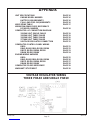
APPENDIX
UNIT SPECIFICATIONS PAGE 16
ENGINE MODEL NUMBER PAGE 16
BATTERY REQUIREMENTS PAGE 16
FULL LOAD FUEL REQUIREMENTS PAGE 16
WIRE SIZING TABLE PAGE 17
WIRING DIAGRAM CROSS REFERENCE
BY MODEL NUMBER PAGE 18
GENERATOR AC CONNECTION DIAGRAM
120/240 VOLT SINGLE PHASE PAGE 19
120/240 VOLT THREE PHASE PAGE 19
120/208 VOLT THREE PHASE PAGE 20
277/480 VOLT THREE PHASE PAGE 20
VOLTAGE REGULATOR CONNECTION PAGE 15
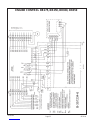
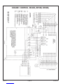
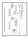
GENERATOR CONTROL PANEL WIRING
DR20 PAGE 21
DR45, DR65, DR90, DR130, DR200 PAGE 22
DR175, DR250, DR300, DR350 PAGE 23
DR400, DR500, DR600 PAGE 24
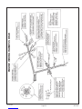
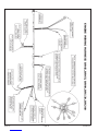
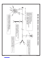
ENGINE WIRING HARNESS
DR20 PAGE 25
DR45, DR65, DR90, DR130, DR200 PAGE 26
DR175, DR250, DR300, DR350 PAGE 27
DR400, DR500, DR600 PAGE 28
GENERATOR CROSS REFERENCE PAGE 29
WARRANTY STATEMENT PAGE 30
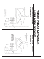
VOLTAGE REGULATOR WIRING
THREE PHASE AND SINGLE PHASE

60708-142Page 168122-00
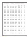
MODEL WATTS VOLTS PF AMP HZ PH ENGINE ENGINE BATTERY FULL LOAD
MODEL VOLTAGE BCI/CCA FUEL REQ.
DR20I4-A 20,000 120/240 1.0 83 60 1 ISUZU 4LE2 12 VOLTS 24/650 1.8 GAL
DR20I4-D 20,000 120/208 0.8 69 60 3 ISUZU 4LE2 12 VOLTS 24/650 1.8 GAL
DR20I4-J 20,000 120/240 0.8 60 60 3 ISUZU 4LE2 12 VOLTS 24/650 1.8 GAL
DR20I4-L 20,000 277/480 0.8 30 60 3 ISUZU 4LE2 12 VOLTS 24/650 1.8 GAL
DR45I4-A 45,000 120/240 1.0 187 60 1 IVECO NEF45 AMI 12 VOLTS 24/650 2.8 GAL
DR45I4-D 45,000 120/208 0.8 156 60 3 IVECO NEF45 AMI 12 VOLTS 24/650 2.8 GAL
DR45I4-J 45,000 120/240 0.8 135 60 3 IVECO NEF45 AMI 12 VOLTS 24/650 2.8 GAL
DR45I4-L 45,000 277/480 0.8 68 60 3 IVECO NEF45 AMI 12 VOLTS 24/350 2.8 GAL
DR65I4-A 65,000 120/240 1.0 270 60 1 IVECO NEF45 SM2 12 VOLTS 24/650 5.2 GAL
DR65I4-D 65,000 120/208 0.8 225 60 3 IVECO NEF45 SM2 12 VOLTS 24/650 5.2 GAL
DR65I4-J 65,000 120/240 0.8 195 60 3 IVECO NEF45 SM2 12 VOLTS 24/650 5.2 GAL
DR65I4-L 65,000 277/480 0.8 97 60 3 IVECO NEF45 SM2 12 VOLTS 24/650 5.2 GAL
DR90I4-A 90,000 120/240 1.0 375 60 1 IVECO NEF45 TM1X 12 VOLTS 31/900 6.8 GAL
DR90I4-D 90,000 120/208 0.8 312 60 3 IVECO NEF45 TM1X 12 VOLTS 31/900 6.8 GAL
DR90I4-J 90,000 120/240 0.8 270 60 3 IVECO NEF45 TM1X 12 VOLTS 31/900 6.8 GAL
DR90I4-L 90,000 277/480 0.8 135 60 3 IVECO NEF45 TM1X 12 VOLTS 31/900 6.8 GAL
DR130I4-A 130,000 120/240 1.0 541 60 1 IVECO NEF67 TE2X 12 VOLTS 31/900 8.9 GAL
DR130I4-D 130,000 120/208 0.8 451 60 3 IVECO NEF67 TE2X 12 VOLTS 31/900 8.9 GAL
DR130I4-J 130,000 120/240 0.8 390 60 3 IVECO NEF67 TE2X 12 VOLTS 31/900 8.9 GAL
DR130I4-L 130,000 277/480 0.8 195 60 3 IVECO NEF67 TE2X 12 VOLTS 31/900 8.9 GAL
DR175I4-A 175,000 120/240 1.0 729 60 1 IVECO NEF67 TE2X 12 VOLTS 4D/1200 10.9 GAL
DR175I4-D 175,000 120/208 0.8 607 60 3 IVECO NEF67 TE2X 12 VOLTS 4D/1200 10.9 GAL
DR175I4-J 175,000 120/240 0.8 526 60 3 IVECO NEF67 TE2X 12 VOLTS 4D/1200 10.9 GAL
DR175I4-L 175,000 277/480 0.8 263 60 3 IVECO NEF67 TE2X 12 VOLTS 4D/1200 10.9 GAL
DR200D4-D 200,000 120/208 0.8 607 60 3 DEUTZ BF4M1013FC 12 VOLTS 4D/1200 15.1 GAL
DR200D4-J 200,000 120/240 0.8 526 60 3 DEUTZ BF4M1013FC 12 VOLTS 4D/1200 15.1 GAL
DR200D4-L 200,000 277/480 0.8 263 60 3 DEUTZ BF4M1013FC 12 VOLTS 4D/1200 15.1 GAL
DR250I4-D 250,000 120/208 0.8 867 60 3 IVECO CURSOR 87 TE1D 24 VOLTS (2) 4D/1200 16.3 GAL
DR250I4-J 250,000 120/240 0.8 751 60 3 IVECO CURSOR 87 TE1D 24 VOLTS (2) 4D/1200 16.3 GAL
DR250I4-L 250,000 277/480 0.8 375 60 3 IVECO CURSOR 87 TE1D 24 VOLTS (2) 4D/1200 16.3 GAL
DR300I4-D 300,000 120/208 0.8 1040 60 3 IVECO CURSOR 10 TE1D 24 VOLTS (2) 4D/1200 21.3 GAL
DR300I4-J 300,000 120/240 0.8 902 60 3 IVECO CURSOR 10 TE1D 24 VOLTS (2) 4D/1200 21.3 GAL
DR300I4-L 300,000 277/480 0.8 451 60 3 IVECO CURSOR 10 TE1D 24 VOLTS (2) 4D/1200 21.3 GAL
DR350I4-D 350,000 120/208 0.8 1214 60 3 IVECO CURSOR 13 TE2X 24 VOLTS (2) 4D/1200 22.2 GAL
DR350I4-J 350,000 120/240 0.8 1052 60 3 IVECO CURSOR 13 TE2X 24 VOLTS (2) 4D/1200 22.2 GAL
DR350I4-L 350,000 277/480 0.8 526 60 3 IVECO CURSOR 13 TE2X 24 VOLTS (2) 4D/1200 22.2 GAL
DR400V4-D 400,000 120208 0.8 1390 60 3 VOLVO TAD1242GE-GS2 24 VOLTS (2) 4D/1200 25.5 GAL
DR400V4-J 400,000 120/240 0.8 1204 60 3 VOLVO TAD1242GE-GS2 24 VOLTS (2) 4D/1200 25.5 GAL
DR400V4-L 400,000 277/480 0.8 602 60 3 VOLVO TAD1242GE-GS2 24 VOLTS (2) 4D/1200 25.5 GAL
DR500V4-J 500,000 120/208 0.8 1734 60 3 VOLVO TAD1641GE-GS2 24 VOLTS (2) 4D/1200 32.2 GAL
DR500V4-J 500,000 120/240 0.8 1503 60 3 VOLVO TAD1641GE-GS2 24 VOLTS (2) 4D/1200 32.2 GAL
DR500V4-L 500,000 277/480 0.8 751 60 3 VOLVO TAD1641GE-GS2 24 VOLTS (2) 4D/1200 32.2 GAL
DR600V4-L 600,000 277/480 0.8 902 60 3 VOLVO TWD1643GE-GS3 24 VOLTS (2) 4D/1200 43.0GAL
Note: De-rate unit power ratings by 3-1/2 % per 1000 feet elevation above sea level.
APPENDIX 1 SPECIFICATIONS TABLES

8122-00
60708-142 Page 17
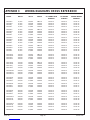
APPENDIX 2
The table below is based on Table 310.16 in the National Electric Code 2008 Edition
Allowable ampacitier of insulated condutors rated 0 through 2000 volts, 750 C through 900C. Not more than
three current-carrying conductors in Raceway, Cable or Earth (Direct Buried). Adjusted for 400C (1040F)
ambient temperature.
Copper Copper Aluminum Aluminum
Copper Clad Aluminum Copper Clad Aluminum
750C90
0C75
0C90
0C
Wire Type:
Wire Type: TBS,SA.
TBS,SA.SIS SIS, THHN
Wire Type: FEP,FEPB,MI,RHH Wire Type: THHW, THW-2
RHW RHW-2,THHN RHW THWN-2,RHH
THHW, THW THHW, THW-2 THHW, THW RHW-2, USE-2
THWN, XHHW XHH, XHHW SIZE AWG THWN, XHHW XHH, XHHW
USE,ZW XHHW-2, ZW-2 OR kcmil USE XHHW-2, ZW-2
44 50 8 35 41
57 68 6 44 55
75 86 4 57 68
88 100 3 66 77
101 118 2 79 91
114 137 1 88 105
132 155 1/0 106 123
154 177 2/0 119 137
176 205 3/0 136 159
202 237 4/0 158 187
224 264 250 180 209
251 291 300 202 232
273 319 350 220 255
295 346 400 238 278
334 391 500 273 319
370 432 600 299 350
405 473 700 330 382
418 487 750 339 396
431 505 800 348 410
458 532 900 374 437
480 560 1000 392 455
519 605 1250 427 496
550 642 1500 458 532
572 669 1750 480 560
585 683 2000 493 573
For addition information see table 310.16 of the National Electric Code

Page 18
8122-00 60708-142
MODEL WATTS VOLTS PHASE AC CONNECTION DC ENGINE ENGINE WIRING
DIAGRAM CONTROL HARNESS
DR20I4-A 20,000 120/240 SINGLE PAGE 19 PAGE 22 PAGE 25
DR20I4-D 20,000 120/208 THREE PAGE 20 PAGE 22 PAGE 25
DR20I4-J 20,000 120/240 THREE PAGE 19 PAGE 22 PAGE 25
DR20I4-L 20,000 277/480 THREE PAGE 20 PAGE 22 PAGE 25
DR45I4-A 45,000 120/240 SINGLE PAGE 19 PAGE 22 PAGE 26
DR45I4-D 45,000 120/208 THREE PAGE 20 PAGE 22 PAGE 26
DR45I4-J 45,000 120/240 THREE PAGE 19 PAGE 22 PAGE 26
DR45I4-L 45,000 277/480 THREE PAGE 20 PAGE 22 PAGE 26
DR65I4-A 65,000 120/240 SINGLE PAGE 19 PAGE 22 PAGE 26
DR65I4-D 65,000 120/208 THREE PAGE 20 PAGE 22 PAGE 26
DR65I4-J 65,000 120/240 THREE PAGE 19 PAGE 22 PAGE 26
DR65I4-L 65,000 277/480 THREE PAGE 20 PAGE 22 PAGE 26
DR90I4-A 90,000 120/240 SINGLE PAGE 19 PAGE 22 PAGE 26
DR90I4-D 90,000 120/208 THREE PAGE 20 PAGE 22 PAGE 26
DR90I4-J 90,000 120/240 THREE PAGE 19 PAGE 22 PAGE 26
DR90I4-L 90,000 277/480 THREE PAGE 20 PAGE 22 PAGE 26
DR130I4-A 130,000 120/240 SINGLE PAGE 19 PAGE 22 PAGE 26
DR130I4-D 130,000 120/208 THREE PAGE 20 PAGE 22 PAGE 26
DR130I4-J 130,000 120/240 THREE PAGE 19 PAGE 22 PAGE 26
DR130I4-L 130,000 277/480 THREE PAGE 20 PAGE 22 PAGE 26
DR175I4-A 175,000 120/240 SINGLE PAGE 19 PAGE 22 PAGE 26
DR175I4-D 175,000 120/208 THREE PAGE 20 PAGE 22 PAGE 26
DR175I4-J 175,000 120/240 THREE PAGE 19 PAGE 22 PAGE 26
DR175I4-L 175,000 277/480 THREE PAGE 20 PAGE 22 PAGE 26
DR200D4-D 200,000 120/208 THREE PAGE 20 PAGE 22 PAGE 26
DR200D4-J 200,000 120/240 THREE PAGE 19 PAGE 22 PAGE 26
DR200D4-L 200,000 277/480 THREE PAGE 20 PAGE 22 PAGE 26
DR250I4-D 250,000 120/208 THREE PAGE 20 PAGE 23 PAGE 27
DR250I4-J 250,000 120/240 THREE PAGE 19 PAGE 23 PAGE 27
DR250I4-L 250,000 277/480 THREE PAGE 20 PAGE 23 PAGE 27
DR300I4-D 300,000 120/208 THREE PAGE 20 PAGE 23 PAGE 27
DR300I4-J 300,000 120/240 THREE PAGE 19 PAGE 23 PAGE 27
DR300I4-L 300,000 277/480 THREE PAGE 20 PAGE 23 PAGE 27
DR350I4-D 350,000 120/208 THREE PAGE 20 PAGE 23 PAGE 27
DR350I4-J 350,000 120/240 THREE PAGE 19 PAGE 23 PAGE 27
DR350I4-L 350,000 277/480 THREE PAGE 20 PAGE 23 PAGE 27
DR400V4-D 400,000 120/208 THREE PAGE 20 PAGE 24 PAGE 28
DR400V4-J 400,000 120/240 THREE PAGE 19 PAGE 24 PAGE 28
DR400V4-L 400,000 277/480 THREE PAGE 20 PAGE 24 PAGE 28
DR500V4-D 500,000 120/208 THREE PAGE 20 PAGE 24 PAGE 28
DR500V4-J 500,000 120/240 THREE PAGE 19 PAGE 24 PAGE 28
DR500V4-L 500,000 277/480 THREE PAGE 20 PAGE 24 PAGE 28
DR600V4-L 600,000 277/480 THREE PAGE 20 PAGE 24 PAGE 28
APPENDIX 3 WIRING DIAGRAMS CROSS REFERENCE
Page is loading ...
Page is loading ...
Page is loading ...
Page is loading ...
Page is loading ...
Page is loading ...
Page is loading ...
Page is loading ...
Page is loading ...
Page is loading ...
Page is loading ...
Page is loading ...
-
 1
1
-
 2
2
-
 3
3
-
 4
4
-
 5
5
-
 6
6
-
 7
7
-
 8
8
-
 9
9
-
 10
10
-
 11
11
-
 12
12
-
 13
13
-
 14
14
-
 15
15
-
 16
16
-
 17
17
-
 18
18
-
 19
19
-
 20
20
-
 21
21
-
 22
22
-
 23
23
-
 24
24
-
 25
25
-
 26
26
-
 27
27
-
 28
28
-
 29
29
-
 30
30
-
 31
31
-
 32
32


Winpower DR600 Operating instructions
- Category
- Power generators
- Type
- Operating instructions
Ask a question and I''ll find the answer in the document
Finding information in a document is now easier with AI
Related papers

Other documents
-
MQ Power DCA220SSJU4F Operating instructions
-
-
-
OPTO 22 Basler DGC-2020 Integration Kit User guide
-
-
-
Winco PSS60B Operating instructions
-
 MULTIQUIP EGC-500C User manual
-
 NorthEast Monitoring DR200/HE User manual
-
AEG DGR9962HB Installation guide

