Page is loading ...

OWNER’S MANUAL
MODEL 515
High-Speed Fabric Roll-Up Door
MANUAL PART #: B

ASI DOORS, INC. (800) 558-7068 asidoors.com
GENERAL
INFORMATION
GENERAL INFORMATION
. . . . . . . . . . . . . . . . . . . . . . . 3-6
Safety Practices . . . . . . . . . . . . . . . . . . . . . . . . . . . . . . . . . . . . 3
Warranty Policy . . . . . . . . . . . . . . . . . . . . . . . . . . . . . . . . . . . . 5
Crates and Contents . . . . . . . . . . . . . . . . . . . . . . . . . . . . . . . . . . 6
MANUAL INSTALLATION
. . . . . . . . . . . . . . . . . . . . . . . . 7-34
Door Measurements . . . . . . . . . . . . . . . . . . . . . . . . . . . . . . . . . . 7
Face Frame Installation . . . . . . . . . . . . . . . . . . . . . . . . . . . . . . . . . 8
Header Installation . . . . . . . . . . . . . . . . . . . . . . . . . . . . . . . . . . 9
Curtain Aligment . . . . . . . . . . . . . . . . . . . . . . . . . . . . . . . . . . . . 11
Frequency Inverter . . . . . . . . . . . . . . . . . . . . . . . . . . . . . . . . . . . 13
Warranty and Liability . . . . . . . . . . . . . . . . . . . . . . . . . . . . . . . . . 14
Electrical Controls . . . . . . . . . . . . . . . . . . . . . . . . . . . . . . . . . . . 15
Electrical Installation . . . . . . . . . . . . . . . . . . . . . . . . . . . . . . . . . . 19
Photoeye Connections . . . . . . . . . . . . . . . . . . . . . . . . . . . . . . . . . 20
Encoder Connections . . . . . . . . . . . . . . . . . . . . . . . . . . . . . . . . . . 23
Wiring Accessories . . . . . . . . . . . . . . . . . . . . . . . . . . . . . . . . . . . 25
Final Checks and Verification . . . . . . . . . . . . . . . . . . . . . . . . . . . . . . 25
Setting Door Limits . . . . . . . . . . . . . . . . . . . . . . . . . . . . . . . . . . . 26
Activation Devices . . . . . . . . . . . . . . . . . . . . . . . . . . . . . . . . . . . 29
Automatic Timer . . . . . . . . . . . . . . . . . . . . . . . . . . . . . . . . . . . . 30
MC/PB Timer . . . . . . . . . . . . . . . . . . . . . . . . . . . . . . . . . . . . . . 31
AC/LOOP Timer . . . . . . . . . . . . . . . . . . . . . . . . . . . . . . . . . . . . 32
Calibrate WDD Reversing Edge . . . . . . . . . . . . . . . . . . . . . . . . . . . . . 33
Photcell Install and Setup . . . . . . . . . . . . . . . . . . . . . . . . . . . . . . . . 34
MAINTENANCE
. . . . . . . . . . . . . . . . . . . . . . . . . . . . 35-38
Error Messages . . . . . . . . . . . . . . . . . . . . . . . . . . . . . . . . . . . . . 35
Preventative Maintenance . . . . . . . . . . . . . . . . . . . . . . . . . . . . . . .
36
Anti-Roll Switch . . . . . . . . . . . . . . . . . . . . . . . . . . . . . . . . . . . . 38
REPLACEMENT PARTS
. . . . . . . . . . . . . . . . . . . . . . . 39-49
Instructions for Ordering . . . . . . . . . . . . . . . . . . . . . . . . . . . . . . . . 39
Mechanical Service Parts List . . . . . . . . . . . . . . . . . . . . . . . . . . . . . . 40
Service Parts - Door Curtain . . . . . . . . . . . . . . . . . . . . . . . . . . . . . . . 42
Service Parts - Motor Side . . . . . . . . . . . . . . . . . . . . . . . . . . . . . . . . 43
Service Parts - Idler Slide . . . . . . . . . . . . . . . . . . . . . . . . . . . . . . . . 44
Service Parts - Side Frames & Drive Assembly . . . . . . . . . . . . . . . . . . . . . . 45
Service Parts - Shrouds . . . . . . . . . . . . . . . . . . . . . . . . . . . . . . . . . 46
Electrical Service Parts List . . . . . . . . . . . . . . . . . . . . . . . . . . . . . . .
47
Service Parts - Electrical . . . . . . . . . . . . . . . . . . . . . . . . . . . . . . . .
48
ADDENDUM
. . . . . . . . . . . . . . . . . . . . . . . . . . . . . . 50-51
Shroud Installation . . . . . . . . . . . . . . . . . . . . . . . . . . . . . . . . . . . 48

ASI DOORS, INC. (800) 558-7068 asidoors.com
Safety Practices
This is a safety alert symbol. It is used to alert you to potential personal injury
hazards. Obey all safety messages that follow this symbol to avoid possible
injury or death.
WARNING indicates a potentially hazardous situation which, if not avoided, could result in
death or serious injury.
CAUTION indicates a potentially hazardous situation which, if not avoided, may result in minor
or moderate injury.
CAUTION used without a safety alert symbol indicates a potentially hazardous situation which,
if not avoided, may result in property damage.
NOTE explains general information.
DANGER indicates an imminently hazardous situation which, if not avoided, will result in death
or serious injury.
NOTE
GENERAL
INFORMATION

ASI DOORS, INC. (800) 558-7068 asidoors.com
Warning read these safety practices before installing, operating or servicing the SLIDING
door. Failure to follow these safety practices could result in property damage, death or
serious injury.
READ AND UNDERSTAND ALL WARNING LABELS AND OPERATING INSTRUCTIONS IN THIS
MANUAL BEFORE OPERATING THE SLIDING DOOR. If you do not understand the instructions,
ask your supervisor to teach you how to use the SLIDING door.
Safety Practices (cont’d)
1. Do not operate the door while under the influence of drugs or alchohol.
2. Do not use the door if it looks broken or does not seem to work properly. Advise your supervisor at
once.
3. Stay clear of the door when it is moving
4. Keep hands, feet and head clear of the door at all times.
5. Do not operate the door with equipment, material or people directly inside door opening.
6. Disconnect power before performing any electrical or mechanical service, cleaning or other mainte-
nance on the door. OSHA requires disconnect to be properly tagged and locked out during all mainte-
nance or service of equipment. With the power supply disconnected, always verify using a volt meter.
7. All electrical troubleshooting or service must be completed by a qualified electrician or service
person and must meet all applicable local, state, federal, international and other governing agency
codes.
8. When it is necessary to service the control box with power on, USE EXTREME CAUTION. Do not place
fingers or uninsulated tools inside the control box. Touching wires or other parts inside the enclosure
may cause electrical shock, serious injury or death.
9. It is your responsibility to keep all warning labels and instructional literature legible, intact and kept
with the door. Replacement labels and literature are availale from ASI Doors, Inc. or its
representatives.
10. If you have any questions, contact your supervisor or your local ASI Doors, Inc. representative for
assistance.
11. Train all service and personnel using or near door on intended use(s) and operation of the door.
12. Failure to operate the door as intended, as described, or heed any warning may result in equipment
damage, property damage, serious bodily injury or death.
GENERAL
INFORMATION

ASI DOORS, INC. (800) 558-7068 asidoors.com
Warranty Policy
ASI Doors (herein called “ASI”) warrants solely for the benefit of its customer that each door system
manufactured by ASI (each a “Door System”) will be free from defects in material and manufacture for a
period of one (1) year from the date of original shipment by ASI. The following models receive a similar
two (2) years from date of shipment warranty: 109, 209, 120-125, 1240-125-, 1240SS-1250SS, 1260-1270,
1260SS-1270SS, 130-135, 140-150, 160-170, 220-225, 220SS-225SS, 230-235, 230SS-235SS. In all instances
warranty labor is covered for a period of one (1) year from the date of original shipment.
The foregoing limited warranty shall not apply to defects that result from improper installation, abuse,
misuse, alteration, modification, or failure to maintain the Door System in accordance with the ASI
Owner’s Manual. Periodic maintenance and adjustment of the Door System as described in the ASI
Owner’s Manual are the sole responsibility of the customer. All claims for defects must be made to
ASI within thirty (30) days aer the defect is discovered or should, with reasonable care, have been
discovered. THE FOREGOING LIMITED WARRANTY CONSTITUTES THE EXCLUSIVE WARRANTY OF ASI
WITH RESPECT TO THE DOOR SYSTEM. ASI EXPRESSLY DISCLAIMS ALL OTHER GUARANTEES OR
WARRANTIES—WHETHER EXPRESSED, IMPLIED, OR STATUTORY, INCLUDING BUT NOT LIMITED TO
ANY IMPLIED WARRANTY OF MERCHANTABILITY AND FITNESS FOR A PARTICULAR PURPOSE.
If a Door System does not comply with the foregoing limited warranty, and a claim is made by customer
within the warranty period, ASI will, at the option of ASI, either repair or replace any defective equipment
or parts free of charge and pay the reasonable labor costs to repair or replace the defective equipment or
parts if within the defined warranty period. The remedy of repair or replacement shall be the exclusive
and sole remedy for any breach of the foregoing limited warranty.
ASI SHALL NOT IN ANY EVENT BE LIABLE FOR ANY INCIDENTAL, INDIRECT, SPECIAL, EXEMPLARY OR
CONSEQUENTIAL DAMAGES OF ANY KIND, INCLUDING WITHOUT LIMITATION ANY LOST PROFITS,
ARISING FROM THE SALE OR USE OF THE DOOR SYSTEM, OR FROM ANY OTHER CAUSE WHATSOEVER,
WHETHER THE CLAIM GIVING RISE TO SUCH DAMAGES IS BASED UPON BREACH OF WARRANTY
(EXPRESSED OR IMPLIED) BREACH OF CONTRACT, TORT, STRICT LIABILITY OR ANY OTHER THEORY
OF LIABILITY, EVEN IF A PARTY HAS BEEN ADVISED OF THE POSSIBILITY THEREOF, AND REGARDLESS
OF ANY ADVISE OR REPRESENTATION THAT MAY HAVE BEEN RENDERED BY ASI CONCERNING THE
SALE OR USE OF THE DOOR SYSTEM.
At ASI’s request, customer shall return to ASI for inspection any Door System for which a warranty claim
has been made, F.O.B. ASI’s facility with freight prepaid. The customer is responsible for any removal
costs.
The customer shall comply with the following procedures in filing a warranty claim with ASI:
1. Notify ASI of any and all defects in writing with photographic evidence. ASI will review the warranty
request and issue a Returns Merchandise Authorization (RMA) form if the defective parts need to be
returned to ASI for inspection and verification. The RMA form must accompany any materials returned for
warranty consideration.
2. All replacement parts or equipment will be invoiced to the customer. Upon verification by ASI that the
Door System is defective, ASI will issue a full credit to customer for the replacement parts or equipment.
3. If outside labor is needed to install the replacement parts or equipment, ASI requires a written
estimate of the labor charges in advance so ASI may approve the labor charges and issue a purchase
order. ASI will not accept any labor charges unless previously approved in writing and accompanied by
the ASI purchase order number.
(Rev 12/21)
GENERAL
INFORMATION

ASI DOORS, INC. (800) 558-7068 asidoors.com
CRATE
SIDE
FRAMES
CONTROL BOX
LOOSE PARTS
BOX
SHROUD ASSEMBLY
(OPTIONAL)
HEADER AND
MOTOR ASSEMBLY
CRATE
Crates and Contents
GENERAL
INFORMATION
Because of variances in the construction of walls on
which the door will be mounted, fasteners are not
supplied. For proper anchoring of the door, we
recommend the use of thru-bolts. DO NOT remove
door sections from crate until you encounter the step in
which they are to be installed.
Unless specically called out as “Provided by ASI”,
installer is to provide all necessary mounting hardware,
anchors, inserts, hangers, supports and equipment
needed to install door in accordance with nal shop
drawings and manufacturer’s instructions.
NOTE
Upon receipt of the shipment, check that you have received the correct number of pieces as shown (Figure 1). Crate
will contain the side-covers, the header assembly, the loose parts box, and control box. For your protection, note
any damages or shortages on the carrier’s bill of lading before signing the bill for receipt.
The installation of this door will require at least a two man crew and a fork-li. Select a fork-li with liing height
based upon the height of the door, plus a minimum additional two feet.
Description Qty.
Installation Instructions 1
Sales Drawing 1
Misc. Activation Devices As Ordered
Warning Name Plate Assembly 2
Control Enclosure Box
Control Box 1
6mm Hex Drive 1
Photo Eyes 2
Schematic 1
Misc. Activation Devices As Ordered
Loose Parts
Figure 1: Crate Contents

ASI DOORS, INC. (800) 558-7068 asidoors.com
Door Measurements
INSTALLATION
1. Make contact with the person responsible at the customer’s place of business – check access conditions and
prevailing safety practices.
2. First check the dimensions of the construction opening. The exact measurements can be found on the
production sheet supplied with the door.
3. Carefully unpack the door and check the various components:
• Le and right side frames.
• Roll-up mechanism and installation manual included in the packing list.
• Control box, wiring diagram, photo eyes and cable for anti-roll o switch.
• Fasteners for the door, the operating controls and other accessories.
Header
17-1/2”
Bolt Hole Locations
1/2 WIC + 3”
Drive Side
3”
1/2 WIC + 3”
Idler Side
3”
Figure 2: Door Measurements Figure 3: Marking Bolt Holes
Description Qty.
Tape Measure 1
Water Level 1
Pencil 1
General Purpose Pliers 1
Wire Cutters 1
Wire Strippers 1
Digital Volt/Ohmmeter 1
Silcone Caulk Gun 1
Hammer 1
Screw Drivers 1
Extension Corder 1
Electric Screwdriver 1
Electric Drill 1
Hammer Drill 1
Set of Contrete Drill Bits 1/4” to 5/8”
Set of Metal Drill Bits 1/4” to 5/8”
Tools Required
9”
21”
Operator

ASI DOORS, INC. (800) 558-7068 asidoors.com
1
2
3
Face Frame Installation
INSTALLATION
Note only ASI Doors qualified personnel are
authorized to carry out this work.
NOTE
Assembly on the floor:
1. The ends of the steel channels with the black plastic
reintroduction blocks go to the in-sides of the header
brackets.
2. Position ends of side track of each side door post flush to
wall side, and bottom edge of the header brackets.
3. Attach both side door posts to the roll/header brackets
using splice bracket and fasteners on 2 studs shown.
Hardware is provided in loose parts box.
Note: reintroduction blocks flex towards center of opening
during door opening and closing.
Do not restrict movement of reintroduction blocks.
1
1

ASI DOORS, INC. (800) 558-7068 asidoors.com
Header Installation
INSTALLATION
Caution protect the drum and door panel during
installation of the door.
Figure 5: Liing of the Door
Liing The Door:
Li the door using the fork li, and move it to the construction opening.

ASI DOORS, INC. (800) 558-7068 asidoors.com
Header Installation Continued
INSTALLATION
Caution the attachment of the foll assembly and the door posts to the wall
must be carried out with appropriate methods. The installer must ensure
that the fasteners are suitable for the size of the door and the type of walls; if
necessary, increase the number of the fasteners used.
1. Measure the floor for level from le to right side and shim under side door posts if necessary.
2. Place the entire structure around the construction opening.
3. The inner dimension B, between the black plastic door guides, must be equal to the width of the door
opening stated on the production data sheet and customer order form that has been supplie with the door.
4. Please ensure that the parts are level/plumb (roll assembly and door posts)
Checks before the Installation of the Door:
Check Level
Check Plumb
Check Plumb
Figure 6: Attachment To The Wall
Note for an optimum seal, the gaps between the
door structure and the walls of the building must be
filled. Please consult the customer with regard to
the choice of materials to be used (caulk,
silicone, etc.).
NOTE

ASI DOORS, INC. (800) 558-7068 asidoors.com
Curtain Alignment
INSTALLATION
Important Tips To Install The Door Properly:
• Insure the bottom of the door curtain is taught but not too tight when closed. A curtain that is too tight will
prevent the door from closing properly.
• Locate and attach the posts to the wall with the mounting screws in the center of slots for adjustment later if
needed.
• Repeat this operation with the bottom of curtain at several dierent heights, to ensure a correct position of the
side door posts for optimum operation and sealing.
Curtain Alignment:
remove the protective packaging of the
roll assembly without damaging the
curtain. Lower the door manually by
turning the motor with the extension
piece supplied at the bottom of the
control box, and in-sert the guiding cord
into the reintroduction block.
When attaching door posts to wall, make
sure that they are plumb & level, and
hold 90° in upper 2 corners. This will
allow curtain to hang straight.
Figure 7: Installing the Curtain Properly
Figure 8: Curtain Alignment

ASI DOORS, INC. (800) 558-7068 asidoors.com
Curtain Alignment Continued
INSTALLATION
Inserting the Retaining Straps Into The Side Guides
Figure 9: inserting the retaining edge. Remove the protective packaging of the roll assembly without damaging the
curtain.
Lower the door down manually by turningthe motor with the extensionpiece supplied at the bottom of the control
box and insert the guiding cord into the reintroduction block.
Figure 9: Inserting the Retaining Edge
Figure 10: Correct Position of the Curtain with Door Open

ASI DOORS, INC. (800) 558-7068 asidoors.com
Curtain Alignment Continued
INSTALLATION
Warning lock the main power disconnect switch (with a padlock) before doing this.
Caution use of a powered drill or impact
driver is NOT recommended, and may
damage the motor or hex drive.
Manually Closing The Door:
Insert the supplied hex drive into the end of the Motor.
Turn the ratchet to move the door open or closed.
6MM Hex Socket Supplied
Figure 11: Manual Opening or Closing Using Ratchet
Danger when a frequency inverter has power supplied to it, the electrical elements and a number of
operating controls are also ‘live’. Never touch these elements. This is extremely dangerous. The cover of
the frequency inverter must always be closed.
When the emergency stop is activated, the frequency inverter remains ‘live’’. If this is a threat to the safety
of the sta, the power circuit must be interrupted by locking the main switch on the control box.
Aer turning o and locking the main power switch, it is always necessary to wait 5 minutes before
starting work. This is the time required to discharge the capacitors of the frequency inverter.
The frequency inverter has integrated safety systems for stopping the door. A mechanical block,
fluctuations in voltage and interruptions of the power supply, can also bring a door to a stop. This is
shown with a fault message on the frequency inverter screen. Aer locking the main switch, and having
removed the blockage, the main switch has to be unlocked and the door opened manually to re-charge
the frequency controller.
In the event of work (on the electrical and/or mechanical part of the installation), the power supply to the
frequency inverter must be switched o; to do this, the main switch on the control box must be locked.
Precautions With The Frequencey Inverter:

ASI DOORS, INC. (800) 558-7068 asidoors.com
Warranty and Liability
INSTALLATION
Warning check all warnings weekly. Door may unexpectedly close. Failure to mount and maintain
all warnging labels and instructional literature could result in death or serious injury.
Warranty claims will only be considered if the door was being operated and treated correctly. In the event of
unauthorized repairs and modification to the construction and the operation of the door, the warranty will be
invalidated. This rule also applies to damage resulting from defects that are the consequence of failure to follow
the operating instructions or of inadequate maintenance of the door.
Figure 12: Warning Label installation - Wall Mount

ASI DOORS, INC. (800) 558-7068 asidoors.com
Electrical Controls
INSTALLATION
WARNING control box contain HIGH VOLTAGE! The following procedures should be performed by
qualified personnel only. Wiring must meet all local, state federal and international or other governing
agency codes. Keep hands and body parts clear of high voltage areas. Failure to do so could result in
death or serious injury.
WARNING disconnect power at the fused disconnect during all electrical or mechanical service.
Disconnect must be properly locked out during maintenance or service or equipment. Failure to do so
could result in death or serious injury.
NOTE wiring must be completed by a licensed electrician. All wiring connections must be in accordance
with alllocal. state, federal, NEC or other governing agency codes. Reference electrical drawings shipped
with door.
NOTE
NOTE refer to electrical schematic for connections.
CAUTION protect and cover all electrical components inside the control box prior to drilling enclosure.
Failure to do so may result in component malfunctions.
1. Make sure prewired cable supplied is of suicient length to enable location of control box where desired. Mount
control box to a convenient location, leaving suicient room for control box door to be opened.
2. All wiring should be installed and connected by a qualified electrician who is knowledgeable with NEC Article
430 and with local regulations. Electrician should make sure that the voltage and frequency of the electrical
supply corresponds with the motor data listed on the Control Box cover.

ASI DOORS, INC. (800) 558-7068 asidoors.com
Electrical Controls Continued
INSTALLATION
NOTE fused disconnect complying with applicable electrical codes must be supplied by others.
NOTE
1. Prewired cable from motor must not be spliced. Run this cable to control box (Figure 15).
2. From a fused disconnect, route power supply wires to the control panel and connect to terminal blocks“L1”,
“L2”, “L3”. Also attach a ground to control panel terminal.
3. All connections for motor, encoder, photoeyes, anti-roll switch, and any activation devices should bemade per
the schematic. All wiring connections from harness must be terminated in the control box(see Figures 15 & 16).
NOTE any wiring by others MUST come into
control box from bottom as shown, or warranty is void.
NOTE
Prewired motor cable
supplied by ASI - installed
by others.
DO NOT SPLICE
Control box
Incoming power and
activators by others.
Encoder, photoeye cables,
and anti-roll switch wires
by ASI. Connections by
others. (See Figure 14)
Figure 13: Wiring Installation

ASI DOORS, INC. (800) 558-7068 asidoors.com
Electrical Controls Continued
INSTALLATION
Install the control box at a location agreed with the user. Check that the power supply agrees with the connections
of the transformer, motor, and frequency inverter. If necessary, modify.
Connect the following in accordance with the electrical diagram and the specific notes supplied with the door:
• The motor- DO NOT SPLICE THE SUPPLIED HIGH VOLTAGE MOTOR CORD – IT HAS SHIELDING THAT IS RE-
QUIRED FOR PROPER DRIVE OPERATION.
• The wires for the absolute encoder that controls the OPEN/CLOSED positions of the door.
• The photoelectric cell wires from each side frame (see illustration below for routing non-drive side cable).
• Opening and Interlocking control devices.
Activate the emergency stop button and check whether the the magneto-thermal main switch is o. Check that the
power cable is not ‘live’ and connect the switch to the power supply.
Figure 14: Electrical Connections
Black
Gray
Gray
Black
Option:
Second set of
Photoeyes
Anti-Roll Switch (mounted on drive
side).
Mark/tape for upper and lower photoeye
cables before pulling through.
An opening has been provided in the
side plate to pull the photoelectric cell
cables through the header tube.
Connect the blue and black wires for the
anti-roll switch to terminals 1 and 4 of
the control box.
Route anti-roll switch wires
through this hole.

ASI DOORS, INC. (800) 558-7068 asidoors.com
Electrical Controls Continued
INSTALLATION
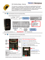
The ASI Doors Door controller monitors all operations of the door.
You use this device to:
• Define the automatic close timers
• Monitor and troubleshoot the input connections
• Interpret and correct any malfunctions or alarms
Note: The door will not run until the controller display reads ‘Ready’.
Figure 15: Controller

ASI DOORS, INC. (800) 558-7068 asidoors.com
Electrical Installation
INSTALLATION
CAUTION ensure that the incoming supply for the door is compatible with the transformer, motor, and
inverter.
Frequency Inverter Voltage Range:
120 V = Single Phase
480 V = 3 Phase
230 V = Single Phase or 3 Phase
208 V = Single Phase or 3 Phase
Failure to ensure compatible power supply may result in fire and will damage the door.
CAUTION refer to the electrical schematic shipped with the door for appropriate circuit protection.
CAUTION ensure that the electrical installation for this door complies with the national electrical code
(NEC) and/or your local electrical code.
Primary Connections
1. Connect the incoming power. CAUTION: run the wires (conduit) through the BOTTOM of the control box, up the
le side, and connect them into the terminal strip or optional disconnect. (See Figure 16). Bringing in power from
the top of the control box will void the warranty.
• For a 3-phase unit, use terminals L1, L2, and L3.
• For a Single Phase unit use terminals L1 and L2.
Power
Connections
Figure 16: Power Connections in he Control Box

ASI DOORS, INC. (800) 558-7068 asidoors.com
Photoeye Connections
INSTALLATION
CAUTION use only the motor cable provided. Do not splice the cable. Doing so will void the warranty.
1. Connect the grounding wire (ground wires and shield wire) to the ground terminals. (See Figure 17)
2. Connect the motor wires (black) to terminals T1, T2, and T3.
3. Make the anti-roll switch connection to the terminal strip.
Figure 17: Ground Connections on Terminal Block
WDD
GND
L1
L2
L3
T2
T3
T1
1
1B
1A
1
1
X2
X2
2
8
4
3
ANTI-ROLL M.S.
PE1
10A 400VAC
ES 11
Ground
T1
T2
T3
Motor Leads
Anti-Roll Switch
(In Door Header, on
Motor Side)
Make the Primary Connections:
/