Page is loading ...

VHF
&
UHF
Antenna
Coast
to
Coast
RV
Services
20
George
Young
Street,
Auburn
NSW
2144
Postal
Address:
PO
Box
415,
Regents
Park
NSW
2143
Phone:
02
9645
7600
Fax:
02
9645
7688
Email
Technical:
technical@coastrv.com.au
Email
Warranty:
warranty@coastrv.com.au
Specifications
•
For
VHF
&
UHF
channels
•
Bidirectional
antenna
•
Operating
dimensions:
43.2
cm
wide
x
116
cm
tall
•
Length
when
stowed:
125.3
cm
•
Height
when
stowed:
11.2
cm
•
Storage
(survival)
temperature:-
40°
C
to
+80°
C
•
For
outdoor
use
only
•
Model
CC-10HV
(Aftermarket)
Product
Registration
Please
register
your
Winegard
product
by
completing
the
online
registration
form
at
http://
www.winegard.com/registration.
2452246

Mounting
Bracket
Other
Hardware
Side
View
Front
of
Antenna
Top
View
Leveling
bracket
Upper
element
housing
Boom
Coax
cable
Directional
Handle
Lower
element
housing
Power
Supply
Weather
boot
Spring
Rotating
gear
housing
Clearance
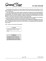
Requirements
The
Winegard
Sensar
HV
antenna
requires
a
minimum
roof
space
of
125.3
cm
x
43.2
cm
for
the
stowed
antenna.
When
stowed,
the
top
of
the
element
housing
rests
11.2
cm
above
the
roof.
The
antenna
requires
a
clearance
radius
of
115.6
cm
for
the
antenna
to
raise
to
the
vertical
position.
Maintain
a
minimum
distance
of
26
cm
from
the
nearest
obstruction
and
from
the
edge
of
the
roof.
125.3
cm
1
Winegard
Sensar
HV
Antenna
Mounting
bracket
Base
Plate
Rotating
gear
housing
Decal
Elevating
Crank
Ceiling
Plate
Nylon
Bearing
Bottom
of
gear
housing
Elevating
Shaft
Base
Plate
11.2
cm
115.6
cm

1
4
3
2
Front
of
43.2
cm
61
cm
to
front
of
RV
Choosing
a
Location
for
the
Antenna
Install
in
dry
conditions
only!
Before
choosing
a
location
for
the
antenna,
contact
your
RV
dealer
or
manufacturer.
Your
RV
may
be
pre-wired
or
have
a
reinforced
area
for
this
system.
When
choosing
a
location
for
the
antenna,
keep
in
mind
that
the
antenna
must
be
mounted
on
or
parallel
to
the
centerline
of
the
coach
with
the
front
of
the
antenna
(the
mounting
bracket)
facing
the
front
of
the
RV.
Front
of
Antenna
NOTE
Choose
a
location
on
the
roof
of
the
RV
that
meets
the
following
requirements:
Offers
enough
support
for
a
secure
installation
Has
a
minimum
roof
space
(clearance)
of
125.3
cm
x
43.2
cm
for
the
stowed
antenna
Allows
antenna
to
raise
and
rotate
without
interference
from
other
roof-mounted
equipment
•
clearance
distance
of
61
cm
from
antenna
to
the
front
of
the
vehicle
•
clearance
radius
of
116
cm
needed
for
antenna
to
raise
to
vertical
position
•
clearance
distance
of
26
cm
needed
from
antenna
to
nearest
obstruction
and
to
the
edge
of
the
roof
26
cm
to
edge
of
roof
26
cm
to
nearest
obstruction
26
cm
to
nearest
obstruction
Is
within
five
degrees
of
level
(for
best
operation,
must
be
within
three
degrees
of
level)
RW-2000
IW-5000
•
For
sloped/rounded
roofs,
Winegard
recommends
model
RW-2000
exterior
roof
wedge
(sold
separately)
to
level
installation.
•
An
interior
wedge
IW-5000
(sold
separately)
is
also
available.
Sold
Separately
Winegard
Sensar
HV
Antenna
2
Front
of
Sold
Separately
Centerline
of
Coach
The
antenna
is
shown
in
the
travel/stowed
position.
125.3
cm

Making
Cable
Entry
Holes
The
ceiling
plate
will
be
mounted
inside
the
vehicle
directly
underneath
the
mounting
bracket.
Make
sure
the
ceiling
area
is
clear
underneath
the
chosen
location
for
the
mounting
bracket.
Use
the
template
on
the
last
page
of
this
manual,
and
drill
a
4.5
cm
hole
through
the
roof
and
ceiling
of
the
vehicle.
Be
careful
not
to
damage
any
wiring
between
the
roof
and
ceiling
when
drilling.
Using
the
template
on
the
back
page,
drill
a
13
mm
hole
for
cable
entry
through
the
roof
of
the
vehicle
only.
Do
not
drill
through
the
ceiling!
Assembling
the
Antenna
Pull
the
e-clip
off
of
the
pin,
and
remove
the
pin
from
the
leveling
bracket.
Set
the
e-clip
and
the
pin
aside—you
will
need
these
later.
E-clip
NOTE
With
the
elements
on
top
of
the
boom,
insert
the
elevating
gear
in-between
the
sides
of
the
leveling
bracket.
The
holes
in
the
sides
of
the
leveling
bracket
and
the
elevating
gear
should
align.
Leveling
bracket
Elevating
gear
Insert
the
pin
through
the
leveling
bracket
and
the
elevating
gear.
Push
the
e-clip
over
the
end
of
the
pin.
Remove
the
cap
from
the
coax
connection
port.
3
Winegard
Sensar
HV
Antenna
1
2
3
1
2
3
4
An
extra
e-clip
has
been
provided,
which
is
in
a
bag
attached
to
the
back
of
the
boom.
Pin
Pin

6
7
1
2
3
5
Run
sealant
around
TIP
the
holes
for
the
mounting
screws,
around
the
hole
for
cable
entry,
and
around
the
bottom
gear
housing.
4
Connect
the
other
end
of
the
140
cm
coax
to
the
6.1
m
coax
using
a
barrel
connector,
and
route
the
6.1
m
coax
to
Continue
to
thread
the
coax
in
an
S-curve
between
the
boom
and
the
bottom
element
housing.
Connect
the
coax
to
the
coax
connection
port,
and
tighten
until
fingertight.
Then,
tighten
¼
turn
more.
Travel
Position
Assembling
the
Antenna,
Cont.
5
Thread
the
140
cm
coax
between
the
boom
and
the
center
of
the
bottom
element
housing.
8
the
location
of
the
power
supply.
Installing
the
Mounting
Bracket
If
using
a
roof
wedge
or
interior
wedge,
put
in
place
before
proceeding
to
install
the
base
plate
or
interior
hardware.
Center
the
elevating
shaft
in
the
4.5
cm
diameter
hole.
Check
with
your
vehicle
manufacturer
to
determine
if
the
provided
screws
are
suitable
for
your
roof.
Temporarily
secure
the
base
plate
to
the
roof
with
two
of
the
provided
screws.
Check
that
the
weather
boot
is
in
place
over
the
boot
collar.
Make
sure
the
antenna
is
in
the
chosen
location.
The
antenna
should
be
in
the
stowed/travel
position.
The
coax
cable
should
be
routed
through
the
ceiling
and
wall
to
the
power
supply.
Apply
a
liberal
amount
of
approved
nonhardening
sealing
compound
on
the
bottom
of
the
base
plate.
This
will
help
to
prevent
leaks.
Do
not
get
sealing
compound
on
bearing
surface
between
base
plate
and
rotating
gear
housing.
Do
not
paint
the
top
of
the
base
plate
or
around
the
rotating
gear
housing.
Using
the
provided
screws,
secure
the
base
plate
to
the
roof.
Run
a
solid
bead
of
sealant
over
the
mounting
screws.
This
will
also
help
to
prevent
leaks.
Winegard
Sensar
HV
Antenna
4

4
the
directional
handle
with
the
keyways
on
the
bottom
of
the
gear
housing.
(The
keys
only
line
up
one
way—do
not
force.)
Carefully
align
the
keys
inside
Pull
the
handle
down,
and
transfer
7
this
dimension
to
the
shaft
end
of
the
directional
handle.
Mark
this,
and
cut
the
handle
at
the
mark.
Push
the
directional
handle
up
into
ceiling
and
over
the
shaft.
Measure
the
distance
between
the
bottom
of
the
recess
on
the
handle
to
the
ceiling.
Determine
the
roof
thickness.
The
mount
is
designed
to
fit
roofs
from
2.5
cm
to
12
cm
thick.
•
If
the
roof
is
less
than
or
equal
to
12
cm
thick,
continue
to
step
2.
•
If
the
roof
is
more
than
12
cm
thick
(max.
17.8
cm),
a
directional
handle
extension
is
needed.
Winegard
recommends
model
EK-1036
directional
handle
extension
(sold
separately).
Lay
the
ceiling
plate
on
top
of
the
directional
handle
with
the
pointers
aligned.
2
Slide
the
ceiling
plate
and
directional
handle
assembly
over
the
rotating
base
shaft.
Make
pilot
holes
in
the
ceiling.
Then,
mount
the
ceiling
plate
with
the
four
provided
screws.
3
The
knobs
on
the
directional
handle
should
fit
into
the
grooves
on
the
ceiling
plate.
3
6
The
pointer
on
the
handle
should
point
toward
the
back
of
the
coach.
The
handle
cut
must
be
flat.
Thick
key
below
ceiling
Cut
shaft
here
Cut
handle
here
Cutting
the
Directional
Handle
to
fit
Roof
Thickness
1
Sold
Separately
2
Inside
the
vehicle,
mark
the
elevating
shaft
3.8
cm
below
the
ceiling.
Cut
the
shaft
on
this
mark.
3.8
cm
Directional
handle
5
Make
sure
the
top
of
the
directional
handle
is
snug
against
the
bottom
of
the
base
plate.
distance
x
distance
x
TIP
Installing
the
Crank
Assembly
1
Pointers
TIP
5
Winegard
Sensar
HV
Antenna
EK-1036
Thin
key

Check
that
the
set
screw
lines
up
with
one
of
the
flat
sides
of
the
rotating
base
shaft.
8
Tighten
the
set
screw
until
it
touches
the
rotating
base
shaft.
Then,
tighten
only
¼
turn
more.
9
The
set
screw
simply
holds
the
elevating
crank
to
the
rotating
base
shaft.
1
2
The
power
supply
should
be
turned
off
when
connecting
cables/wires.
Back
of
Power
Supply
5
5
7
Set
Slide
the
spring
over
the
rotating
base
shaft.
Installing
the
Crank
Assembly,
Cont.
4
Remove
the
backing
from
the
decal,
and
place
the
decal
on
the
bottom
of
the
directional
handle.
7
Slide
the
elevating
crank
(with
nylon
bearing
on
top)
onto
the
rotating
base
shaft.
screw
NOTE
Installing
the
Power
Supply
The
power
supply
may
be
flush
mounted
in
most
standard
electrical
boxes.
To
flush
mount,
cut
a
hole
in
the
wall
to
fit
the
box.
Run
two
#12
wires
between
the
wall
plate
and
+12
VDC
source,
and
route
downlead
cable
to
this
location.
Front
of
Power
Supply
Do
not
connect
high
current
devices
such
as
hair
dryers
to
this
receptacle.
Maximum
current
rating
of
receptacle
is
8
amps
at
+12
VDC.
Select
a
location
for
the
power
supply.
Make
12
volt
connection
to
the
power
supply.
Install
terminals
on
wires
from
+12
VDC
source,
and
crimp
the
terminals
with
an
appropriate
crimping
tool.
If
in
doubt
as
to
the
polarity
of
the
wires,
connect
them
temporarily
to
the
tabs,
and
press
the
“ON”
switch
on
front
of
wall
plate;
if
light
comes
on,
polarity
is
correct.
Turn
power
off.
Winegard
Sensar
HV
Antenna
6
5
Place
the
nylon
bearing
over
the
top
of
the
crank.
6

Raising
Antenna
2
Turning
on
Power
Supply
Turn
power
supply
on
to
use
either
front
or
rear
output
of
the
TV
outlet.
Neither
outlet
will
work
unless
the
power
supply
switch
is
on.
Lowering
Antenna
to
Travel
Position
Rotate
the
antenna
until
the
pointer
on
the
directional
handle
aligns
with
the
pointer
on
the
ceiling
plate.
Turn
elevating
crank
counterclockwise
in
the
“DOWN”
direction
about
13
turns
or
until
some
resistance
is
noted.
The
antenna
is
now
in
the
travel
position.
4
1
2
3
4
Don
’t
Don’t
force
the
elevating
crank
up
or
down
or
rotate
the
directional
handle
hard
against
stops.
Don’t
travel
with
the
antenna
in
the
up/deployed
position.
Stow
the
antenna
before
traveling
or
when
wind
speeds
reach
+113
km/h,
or
you
will
void
your
warranty.
Don’t
leave
the
antenna
partially
deployed.
Don’t
apply
sealant
over
the
top
of
the
base
plate.
1
2
3
4
Antenna
reception
may
vary
based
on
transmitting
antenna
tower
height,
lobe
pattern
of
the
transmitter,
height
of
the
receiving
antenna,
weather
conditions
and
terrain
on
receiving
path
including
trees,
buildings
and
hills.
Installing
the
Power
Supply,
Cont.
Connect
the
coax
cable
from
the
antenna
to
the
“ANTENNA”
port
on
the
power
supply,
and
tighten
until
fingertight.
(The
coax
cable
should
have
been
routed
through
the
ceiling
and
wall
to
the
chosen
wall
plate
location.)
If
the
connector
is
removed
before
routing
the
coax
cable,
see
page
9
for
help
re-installing
the
connector.
If
hooking
up
the
antenna
to
a
second
television,
connect
another
coax
cable
from
the
“SET
2”
port
on
the
back
of
the
power
supply
to
the
“Antenna
In” port
on
the
second
television.
If
hooking
up
a
cable
input,
connect
the
cable
from
the
cable
input
to
the
“CABLE” port
on
the
back
of
the
power
supply.
Mount
the
power
supply
in
wall
with
the
provided
screws.
Connect
the
72”
coax
cable
from
the
coax
port
on
the
front
of
the
power
supply
to
the
“Antenna
In”
coax
port
on
the
TV.
Press
the
“ON”
switch
on
the
front
of
the
power
supply,
and
check
that
the
light
is
on.
Operation
1
Turn
the
elevating
crank
clockwise
in
“UP”
direction
about
13
turns
or
until
some
resistance
to
turning
is
noted.
3
Rotating
Antenna
for
Best
Picture
Make
sure
the
antenna
is
in
the
“UP”/deployed
position.
Pull
down
with
both
hands
to
disengage
ceiling
plate.
For
analog
signals,
rotate
for
best
picture.
For
digital
signals,
run
a
channel
scan
to
find
the
best
signal.
NOTE
Lower
the
antenna
to
the
travel
position
before
traveling!
Do
Check
parking
location
for
obstructions
before
raising
the
antenna.
Carefully
raise,
lower,
and
rotate
the
antenna.
If
having
trouble,
check
for
obstructions.
Rotate
slowly
when
selecting
a
station,
and
check
the
fine-tuning
on
the
TV.
Lower
the
antenna
to
the
travel
position
before
moving
the
vehicle.
7
Winegard
Sensar
HV
Antenna
3
4
5
6
7
ON
OFF
On/Off
Button
Ceiling
Plate

TEST
POINT
#1
+12
VDC
at
Antenna
2nd
Set
No
+12
VDC
at
this
point
+12
VDC
at
TEST
POINT
#2 Antenna
Jack
1
2
Checking
the
Operation
of
the
Power
Supply
Tune
the
television
receiver
to
the
nearest
station,
and
rotate
the
antenna
for
the
best
picture
and
sound.
This
unit
is
equipped
with
a
polyswitch,
a
current
limiting
device,
which
will
shut
down
+12
VDC
if
there
is
a
direct
short
between
the
antenna
and
power
supply.
The
green
indicator
light
will
not
light.
Once
short
is
eliminated,
the
device
will
reset
itself.
Maintenance
Lubricate
gears
3–4
times
a
year
for
optimal
performance.
Use
silicone
spray
to
lubricate
gears.
Never
use
WD-40
oil
for
it
will
damage
the
gears!
3–4
times
a
year
or
in
the
event
that
rotating
the
antenna
becomes
difficult,
use
silicone
spray
to
lubricate
the
elevating
gear.
Apply
a
liberal
amount
of
silicone
spray
lubricant
to
the
elevating
gear.
The
lift
should
be
in
the
down
position.
Then,
run
the
lift
up
and
down
to
distribute
the
lubricant
over
gears.
(This
is
easiest
if
one
person
cranks
up
and
down
from
inside
the
vehicle
while
another
person
sprays
the
gears.)
Troubleshooting
Do
not
install
couplers,
splitters,
etc.
between
the
power
supply
and
the
antenna.
Installation
of
any
item
on
the
downlead
may
cause
a
short
in
the
system.
The
downlead
supplies
+12
VDC
to
the
preamp
in
the
antenna.
The
power
supply
should
be
turned
OFF
when
connecting/disconnecting
cables
to
power
supply
and
antenna
but
should
be
turned
ON
when
testing
for
voltage.
Testing
System
Make
sure
TV
set
is
working
properly.
Switch
power
supply
ON
and
OFF
while
checking
for
difference
in
picture
quality.
If
there
is
no
difference,
continue
with
step
3.
Disconnect
the
cable
from
the
antenna,
and
check
for
+12
VDC
at
Test
Point
#1.
If
there
is
+12
VDC
at
Test
Point
#1,
there
may
be
a
problem
with
the
antenna.
If
there
is
NO
+12
VDC
at
Test
Point
#1,
reconnect
cable
to
antenna.
Remove
power
supply
from
wall,
and
visually
inspect
for
burned/broken
parts.
If
there
are
ANY
broken/
burned
parts,
replace
power
supply.
Ground
+12
VDC
Disconnect
cable
from
antenna
jack
on
power
supply.
Check
for
+12
VDC
at
Test
Point
2.
If
+12
VDC
is
present,
there
is
a
problem
with
the
cable
connecting
the
power
supply
to
the
antenna.
Repair/replace
cable.
If
+12
VDC
is
not
present
at
Test
Point
#
2,
be
sure
the
green
indicator
light
is
ON.
If
not,
check
the
polarity
of
the
ground
and
+12
VDC
source
wires
to
make
sure
there
are
12VDC
present.
If
there
is
still
no
+12
VDC,
replace
power
supply.
Winegard
Sensar
HV
Antenna
8
1
2
3
4
5
6
15/
16”
Cap
Lubricate
here
around
elevating
gear

Fray
braid
back
as
far
as
outer
cover
will
allow.
Strip
outer
cover
back
12
mm
from
end
of
cable.
TIP
Trim
braid
close
to
outer
cover,
and
remove
6
mm
of
inner
insulation,
being
careful
not
to
nick
the
center
conductor.
Make
sure
no
foil
or
braid
can
touch
center
conductor.
Slide
connector
tip
between
braid
and
inner
insulation
(braid
and
foil,
on
foil
shield
cable).
Push
connector
on
cable
as
far
as
it
will
go.
Attach
cable
with
proper
crimping
or
compression
tool.
Do
not
crush
cable
outn
of-round.
If
installing
in
hot
weather,
increase
these
dimensions
3
mm.
Installing
Connector
on
Coax
Cable
Tools
Needed:
Cable
stripper
Compression
tool
for
compression
connectors
Hex
crimp
tool
for
hex
crimp
connectors
Notes

Mount
Parts
ORDERING
REPAIR
PARTS
Plug
Worm
Gear
Gear
Housing
Nylon
Bearing
Q-Ring
Mounting
Screw
Base
Plate
Nylon
Bearing
Nut
Directional
Handle
&
Ceiling
Plate
Ceiling
Plate
(white)
Screw
Directional
Handle
(white)
Decal
Spring
Nylon
Bearing
Crank
(white)
Repair
parts
are
available
at
many
RV
dealers
and/or
service
centers
throughout
the
country.
If
you
don't
have
a
dealer/service
center
near
you,
call
Winegard
Company
at
1-800-288-8094.
All
major
credit
cards
accepted.
Parts
are
available
only
in
the
packages
shown
on
the
following
pages.
Order
by
the
model
number
of
the
package
needed.
Example:
To
order
the
elevating
gear,
order
RP-3000.
Tax,
shipping
and
handling
additional.

Screw
(white)
Element
Terminal
Parts
Antenna
Head
&
Boom
Antenna
Decal
Antenna
55”
Coax
Assembly
Boom
E-clip
Elevation
Gear
Additional
Hardware
Connector
Wall
Plate
(white)
20’
Coax
Cable
72”
Coax
Cable

Replacement
Kits
&
Parts
CC-RPHV:
Antenna
Element
CC-25HV:
Retrofit
Kit
(Head
Only)
Part
Description
Quantity
Part
Description
Quantity
Antenna
Decal
(unattached)
1
Antenna
Decal
1
Antenna
Element
1
CC-25HV
Manual
1
55”
Coax
Assembly
1
Boom
Assembly
1
CC-RPHV
Manual
1
55”
Coax
Assembly
1
RP-0154:
Boot
Part
Description
Quantity
Boot
(light
gray)
1
RP-2658:
Nylon
Bearing
(for
Crank)
Part
Description
Quantity
RP-2049:
Gear
Housing
Assembly
Nylon
Bearing
1
Part
Description
Quantity
Gear
Housing
1
RP-3000:
Elevation
Gear
Pin
2
Part
Description
Quantity
Nylon
Nut
1
Elevation
Gear
1
Nylon
Bearing
(for
gear
housing)
1
RP-3523:
Base
Plate
E-Clip
2
Part
Description
Quantity
Q-Ring
1
Base
Plate
1
Nylon
Bearing
(for
base
plate)
1
Mounting
Screw
10
Light
Gray
Boot
1
RP-5895:
Crank
(Ivory)
RP-6795:
Crank
(White)
Part
Description
Quantity
Part
Description
Quantity
Crank
(ivory)
1
Crank
(white)
1
RP-6200:
Directional
Handle
&
Ceiling
Plate
(Ivory)
RP-6300:
Directional
Handle
&
Ceiling
Plate
(White)
Part
Description
Quantity
Part
Description
Quantity
Spring
1
Spring
1
Decal
1
Decal
1
Ceiling
Plate
(ivory)
1
Ceiling
Plate
(white)
1
Directional
Handle
(ivory)
1
Directional
Handle
(White)
1
Screw
4
Screw
4
Elev.Shaft
&
Worm
Gear
Repl.
Manual
1
Elev.Shaft
&
Worm
Gear
Repl.
Manual
1
RP-4000:
Worm
Gear
Assembly
RP-6822:
Spring
Part
Description
Quantity
Part
Description
Quantity
Worm
Gear
1
Spring
1
Plug
1
Manual
1

WINEGARD
MOBILE
PRODUCTS
LIMITED
WARRANTY
(2
YEARS
PARTS;
1
YEAR
LABOR)
Winegard
Company
warrants
this
product
against
defects
in
materials
or
workmanship
for
a
period
of
two
(2)
years
from
the
date
of
original
purchase.
During
year
one
(1)
of
such
warranty,
Winegard
Company
will
also
pay
authorized
labor
costs
to
an
authorized
Winegard
dealer
to
repair
or
replace
defective
products.
No
warranty
claim
will
be
honored
unless
at
the
time
the
claim
is
made,
Customer
presents
proof
of
purchase
to
an
authorized
Winegard
dealer
(to
locate
the
nearest
authorized
Winegard
dealer,
contact
Winegard
Company,
3000
Kirkwood
Street,
Burlington,
Iowa
52601,
Telephone
800-288-8094
or
visit
www.winegard.com).
Customer
must
provide
proof
of
purchase
with
a
dated
sales
receipt
for
the
Winegard
product
to
verify
the
product
is
under
warranty.
If
the
date
of
purchase
cannot
be
verified,
the
warranty
period
shall
be
considered
to
begin
thirty
(30)
days
after
the
date
of
manufacture.
If
a
defect
in
material
or
workmanship
is
discovered,
Customer
may
take
the
product
to
an
authorized
Winegard
dealer
for
service.
Customer
must
provide
proof
of
purchase
to
verify
the
product
is
under
warranty.
If
the
product
is
brought
to
an
authorized
Winegard
dealer
for
service
prior
to
expiration
of
year
one
(1)
of
the
warranty
period
and
a
defect
in
material
or
workmanship
is
verified
by
Winegard
Technical
Services,
Winegard
Company
will
cover
the
Winegard
dealer
’s
labor
charges
for
warranty
service.
The
Winegard
dealer
must
contact
Winegard
Technical
Services
in
advance
for
pre-approval
of
the
service.
Approval
of
the
service
is
at
the
sole
discretion
of
Winegard
Company.
Alternatively,
Customer
may
ship
the
product
prepaid
to
Winegard
Technical
Services
(located
at
3111
Kirkwood
Street,
Burlington,
Iowa
52601,
Telephone
800-788-4417).
Customer
must
return
the
product
along
with
a
brief
description
of
the
problem
and
provide
Winegard
Technical
Services
with
Customer
’s
name,
address,
and
phone
number.
Customer
must
also
provide
proof
of
purchase
to
verify
the
product
is
under
warranty.
If
the
product
is
returned
before
the
expiration
of
the
warranty
period,
Winegard
Company
will
(at
its
option)
either
repair
or
replace
the
product.
This
Limited
Warranty
does
not
apply
if
the
product
has
been
damaged,
deteriorates,
malfunctions
or
fails
from:
improper
installation,
misuse,
abuse,
neglect,
accident,
tampering,
modification
of
the
product
as
originally
manufactured
by
Winegard
in
any
manner
whatsoever,
removing
or
defacing
any
serial
number,
usage
not
in
accordance
with
product
instructions
or
acts
of
nature
such
as
damage
caused
by
wind,
lightning,
ice
or
corrosive
environments
such
as
salt
spray
and
acid
rain.
This
Limited
Warranty
also
does
not
apply
if
the
product
becomes
unable
to
perform
its'
intended
function
in
any
way
as
a
result
of
the
television
signal
provider
making
any
changes
in
technology
or
service.
RETURN
AUTHORIZATION
POLICY
A
Return
Material
Authorization
(RMA)
is
required
prior
to
returning
any
product
to
Winegard
Company
or
Winegard
Warranty
Services
under
this
warranty
policy.
Please
call
our
Technical
Services
Department
at
800-788-4417
or
send
an
email
to
warranty@winegard.com
to
obtain
the
RMA
number.
Please
furnish
the
date
of
purchase
when
requesting
an
RMA
number.
Enclose
the
product
in
a
prepaid
package
and
write
the
RMA
number
in
large,
clear
letters
on
the
outside
of
the
package.
To
avoid
confusion
or
misunderstanding,
a
shipment(s)
without
an
RMA
number(s)
or
an
unauthorized
return(s)
will
be
refused
and
returned
to
Customer
freight
collect.
WINEGARD
COMPANY
DOES
NOT
ASSUME
ANY
LIABILITIES
FOR
ANY
OTHER
WARRANTIES,
EXPRESS
OR
IMPLIED,
MADE
BY
ANY
OTHER
PERSON.
ALL
OTHER
WARRANTIES
WHETHER
EXPRESS,
IMPLIED
OR
STATUTORY
INCLUDING
WARRANTIES
OF
FITNESS
FOR
A
PARTICULAR
PURPOSE
AND
MERCHANTABILITY
ARE
LIMITED
TO
THE
TWO
YEAR
PERIOD
OF
THIS
WARRANTY.
In
states
that
do
not
allow
limitations
on
implied
warranties,
or
the
exclusion
of
limitation
of
incidental
or
consequential
damages,
the
above
limitations
or
exclusions
do
not
apply.
Some
states
do
not
allow
limitations
on
how
long
an
implied
warranty
lasts,
or
the
exclusion
of
limitation
of
incidental
or
consequential
damages,
so
the
above
limitations
or
exclusions
may
not
apply
to
you.
This
warranty
gives
Customer
specific
legal
rights.
Customer
may
also
have
other
rights
that
may
vary
from
state
to
state.
SATELLITE
RECEIVER
WARRANTY:
See
manufacturer
’s
limited
warranty
policy.
Disclaimer:
Although
every
effort
has
been
made
to
ensure
that
the
information
in
this
manual
is
correct
and
complete,
no
company
shall
be
held
liable
for
any
errors
or
omissions
in
this
manual.
Information
provided
in
this
manual
was
accurate
at
time
of
printing.
If
the
antenna
does
not
function
as
expected,
please
contact
Winegard
Company
at
1-800-788-4417,
or
visit
our
website
at
www.winegard.com.
800-288-8094
•
Fax
319-754-0787
•
www.winegard.com
•
Printed
in
U.S.A.
Winegard
is
a
registered
trademark
of
Winegard
Company.
All
trademarks
are
property
of
their
respective
owners.
WS-MOBWARREV2
Rev.
1/10

Drill
through
roof.
Do
not
drill
through
ceiling!
4.5
cm
Drill
completely
through
ceiling.
FRONT
OF
RV
13
mm
BACK
OF
RV

/