Orient Technologies BTP-2002NP Installation guide

Category
POS/mobile printers
Type
Installation guide

Orient Technologies BTP-2002NP is a single station thermal printer capable of printing receipts and labels with a maximum width of 82.5mm. It features an auto-cutter, a feed button for manual paper feeding, and a variety of interface options including RS-232 serial. With its compact design and reliable performance, the BTP-2002NP is ideal for use in retail, hospitality, and other commercial applications.

Orient Technologies BTP-2002NP is a single station thermal printer capable of printing receipts and labels with a maximum width of 82.5mm. It features an auto-cutter, a feed button for manual paper feeding, and a variety of interface options including RS-232 serial. With its compact design and reliable performance, the BTP-2002NP is ideal for use in retail, hospitality, and other commercial applications.

I
I
N
N
S
S
T
T
A
A
L
L
L
L
A
A
T
T
I
I
O
O
N
N
M
M
A
A
N
N
U
U
A
A
L
L
Single Station Thermal Printer
z This printer has been manufactured and branded for ORIENT Technologies
B.V. by Shandong New
Beiyang Information Technology Co., Ltd.
z Design and specifications are subject to change without notice. Ask your
supplier for technical specifications before purchase and/or use.
z Whenever in doubt about safety issues that might arise from using this product,
please contact the supplier immediately for assistance.
M
M
o
o
d
d
e
e
l
l
:
:
B
B
T
T
P
P
-
-
2
2
0
0
0
0
2
2
N
N
P
P
BTP-2002NP Installation manual
- 1 -
Declarations
Changes without notice
Information in this document is subject to change without notice. ORIENT Technologies bv
(hereinafter referred to as “ORIENT Technologies”) and SHANDONG NEW BEIYANG
INFORMATION TECHNOLOGY CO., LTD. (hereinafter referred to as “SNBC”) reserves the right
to improve products as new technology, components, software, and firmware become available.
If users need further data about this product or have any doubt about safety issues that might
arise from using it, please feel free to contact ORIENT Technologies, SNBC or your local agents.
Copyright
No part of this document may be reproduced or transmitted in any form or by any means,
electronic or mechanical, for any purpose without the express written permission of ORIENT
Technologies or SNBC.
Copyright © 2007 by SNBC
Printed in China
Version 1.1
Trademarks
Our registered trademarks are
Warnings and Cautions in this manual
Warning: Items shall be strictly followed to avoid damages to body and equipment.
Caution: Items with important information and prompts for operating the printer.
Certifications
The quality control system of SNBC has been approved of the following certification.
(DNV)ISO9001:2000
The environmental control system of SNBC has been approved of the following certification.
(DNV)ISO14001:2004
BTP-2002NP has been approved of the following certification.
WEEE directive 2002/96/EC
ORIENT Technologies bv is complying with all aspects of the European Union’s WEEE directive
2002/96/EC. All the customers and end-users can send the products that have reached the end
of their lifes and are to be recycled, to ORIENT Technologies bv. ORIENT Technologies bv will
take care of the recycling of these products in an environmentally responsible manner in
accordance with WEEE directive.
BTP-2002NP Installation manual
- 2 -
Contact us
In CHINA:
Address: No.169 Huoju Rd, Weihai, Shandong, China. 264209
Hot line: +86-631-5673777
Fax: +86-631-5673778
E-mail: sales@newbeiyang.com
Website: www.newbeiyang.com (via Contact button)
In EUROPE: ORIENT Technologies bv
Address: Meerheide 115, 5521 DX Eersel, The Netherlands
Hot line: +31-497-331080
Fax: +31-497-386430
Website: www.orient-technologies.com (via Contact button)
BTP-2002NP Installation manual
- 1 -
CONTENT
GENERAL SAFETY INFORMATION.....................................................2
1 PARTS IDENTIFICATIONS............................................................3
2 SETTING UP THE PRINTER .........................................................5
2.1 Unpacking ..............................................................................5
2.2 Connecting the Cables..........................................................5
2.2.1 Interface Connector.............................................................6
2.2.2 Cash Drawer Connector......................................................8
2.3 Loading the Paper Roll .........................................................8
3 SWITCH, BUTTON AND LED......................................................11
3.1 Power Switch .......................................................................11
3.2 Feed Button..........................................................................11
3.3 LED........................................................................................11
4 SELF-TEST...................................................................................12
5 HEXADECIMAL DUMP................................................................12
6 SPECIFICATIONS ........................................................................13
6.1 General Specifications........................................................13
6.2 Auto Cutter Specifications .................................................14
6.3 Interface................................................................................14
6.4 Electric Parameters of the Power Supply.........................14
6.5 Environmental Conditions..................................................14
6.6 Reliability..............................................................................15
6.7 Black Mark Specifications..................................................15
6.8 Overall Dimension...............................................................16
7 FEED BUTTON CONFIGURATION .............................................16
BTP-2002NP Installation manual
- 2 -
General Safety Information
Before installing and using the printer, please read the following items carefully.
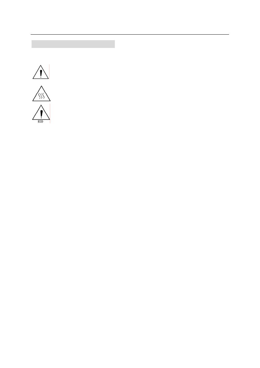
Safety Labels
Don’t touch the cutter and tear bar of printer.
The print head is a thermal element and it is at high temperature during printing or
just after operation, therefore please do not touch it and its peripherals for safety
reasons.
The thermal head is an ESD-sensitive device. To prevent damage, do not touch
either its printing part or connecting parts.
Caution
Install the printer on a flat and stable place.
Reserve adequate space around the printer so that convenient operation and maintenance
can be performed.
Keep the printer away from water source.
Do not use or store the printer in a place exposed to heat of fire, moisture, serious pollution
and direct sunlight.
Do not place the printer on a place exposed to vibration or impact.
No dew condensation is allowed to the printer. In case of such condensation, do not turn on
the power until the condensation has completely gone away.
Connect the AC adapter to an appropriate grounded mains outlet. Avoid sharing the mains
outlet with large power motors and other devices that may cause the fluctuation in voltage.
Disconnect the AC adapter when the printer is not used for a long time.
The socket-outlet shall be installed near the equipment and shall be easily accessible.
Don’t spill water or other materials on the printer. If this happens, turn off the power
immediately.
Do not allow the printer to start printing when there is no printer paper installed, otherwise the
print head and platen roller might be damaged.
To ensure quality print and normal lifetime, use recommended or good quality printer paper.
Shut down the printer when connecting or disconnecting interfaces connectors to avoid
damage to the control board.
Set the print darkness to a lower grade as long as the print quality is acceptable. This will help
to lengthen the print head life-time.
The printer should only be disassembled or repaired by a technician, who is certified by the
manufacturer or by ORIENT Technologies bv.
Keep this manual safe and at hand for ready reference.
BTP-2002NP Installation manual
- 3 -
Parts Identifications
1 Cutter cover
2 Tear bar
3 Printer top cover
4 Power LED
Indicating power status (ON/OFF).
5 Error LED
The red LED indicates basic
information about the status of the
printer. When the LED is off, the
printer is operating normally. A
flashing red LED means the printer
needs operator assistance (such as paper end).
6 Feed button
Under normal status (no error), press it to feed paper. To feed long
lengths of paper, press the key continuously.
7 Top cover latch
8 Power switch
Turning on/off the power for the printer.
“O”-power is turned off;
“—”-power is turned on.
9 Power connector
10Cash drawer connector
11Communication interface
BTP-2002NP Installation manual
- 4 -
12Cutter acting blade
13Printer platen
14Cutter fixed blade
15Paper end sensor
For continuous paper, this sensor is
used to detect whether the paper roll
has run out.
16Paper-width-adjust module
There are 4 long slots at the base of paper holder, putting the
paper-width-adjust module in different slot will allow the printer to use
different width papers listed as follows:80±0.5 mm, 76±0.5 mm, 69.5±
0.5 mm, 57.5±0.5 mm. Removing the paper-width-adjust module will
allow a paper width 82.5 ±0.5mm.
Caution: Paper-width-adjust module is an indispensable part of printer
and should be kept safely.
17
Top cover position sensor
The sensor is used to detect whether the top cover is closed or not.
BTP-2002NP Installation manual
- 5 -
Setting UP the Printer
2.1 Unpacking
Your printer box should include these items. If any items are damaged or
missing, please contact your dealer for assistance.
2.2 Connecting the Cables
You can connect up the cables required for printing to the printer. They all
connect to the connector panel on the back printer, which is shown below:
Before connecting any of the cables, make sure that both the printer and the
computer are turned off.
BTP-2002NP Installation manual
- 6 -
2.2.1 Interface Connector
RS-232 serial interface (DB25F)
Pin
Signal
name
Signal
direction
Function
1 FG Frame ground
2 TXD Output Transmit data
3 RXD Input Receive data
4 RTS Output Same as DTR signal
6
DSR Input This signal indicates whether the host computer can
receive data.
SPACE indicates that the host computer can receive
data, and MARK indicates that the host computer
cannot receive data.
When DTR/DSR control is selected, the printer
transmits data after confirming this signal (except when
transmitting data by DLE EOT, and GS a).
When XON/XOFF control is selected, the printer does
not check this signal.
7 SG Signal ground
20 DTR Output 1) When DTR/DSR control is selected, this signal
indicates whether the printer is busy. SPACE
indicates that the printer is ready to receive data,
and MARK indicates that the printer is busy.
2) When XON/XOFF control is selected:
The signal acts the same as when DTR/DSR
control is selected.
BTP-2002NP Installation manual
- 7 -
Parallel interface
Pin Source Function Pin Source Function
1 H NStrobe 19 Signal Ground (nStrobe)
2 H
Data 0
(Least Significant Bit)
20 Signal Ground (Data 1)
3 H Data 1 21 Signal Ground (Data 2)
4 H Data 2 22 Signal Ground (Data 3)
5 H Data 3 23 Signal Ground (Data 4)
6 H Data 4 24 Signal Ground (Data 5)
7 H Data 5 25 Signal Ground (Data 6)
8 H Data 6 26 Signal Ground (Data 7)
9 H
Data 7
(Most Significant Bit)
27 Signal Ground (Data 8)
10 P NAck 28
Signal Ground
(PError, Select, and nAck)
11 P Busy 29
Signal Ground
(Busy and nFault)
12 P Perror 30
Signal Ground
(nAutoFd, nSelctIn, and
nInit)
13 P Select 31 H NInit
14 H nAutoFd 32 P NFault
15 Not defined 33
Not defined
16 Logic Gnd 34 Not defined
17 Chassis Gnd 35 Not defined
18 P Peripheral Logic High 36 H nSelectIn
Ethernet
Pin Number Signal Name Function
1 TX+ Output Data+
2 TX- Output Data -
3 RX+ Input Data+
4 NC
5 NC
6 RX- Input Data -
7 NC
8 NC
BTP-2002NP Installation manual
- 8 -
USB interface
Pin Number Signal Name Function
1 VBUS +5V
2 DATA- Printer data transmit line minus
3 DATA+ Printer data transmit line plus
4 GND Ground
2.2.2 Cash Drawer Connector
The drawer kick-out drive pulses are generated by command. The host can
retrieve the status of the drawer by using the DLE EOT, GS a, or GS r
commands.
1) Pin assignments:
Pin Number Signal Name Function
1 Frame GND --
2 Drawer kick-out drive signal 1 Output Data
3 Drawer open/close signal Input Data
4 +24 V --
5 Drawer kick-out drive signal 2 Output Data
6 Signal GND --
2) Connector model:
Printer side: DuoYuan DY126-6P6C or equivalent
User side: 6-position 6-contact (RJ11 telephone jack)
3) Drawer kick-out drive signal
Output signal: Output voltage: Approximately 24V
Output current: 1A or less
2.3 Loading the Paper Roll
Note: Be sure to use paper rolls that meet the specifications. Do not use paper
rolls that have the paper glued to the core because the printer cannot
detect the paper end correctly. (Turn off power switch).
1) Turn off the printer.
2) Open the printer top cover, as in following figure.
3) Put the paper roll into the paper holder. See figure below.
BTP-2002NP Installation manual
- 9 -
Caution:
Adjust the paper width by adjusting the paper-width-adjust module
according to the paper type used.
Make sure that the paper roll is cut according to the requirement below
before loading:
Make sure that the heat sensitive side of paper faces the print head and
the rolling direction of paper meets the requirements.
The paper roll should be kept from being loose. Or it may cause paper
jam or other malfunction.
The paper roll should be balanced in the paper holder and not be inclined
because it can affect paper auto loading and printing.
4) Pull the end of the paper roll out up to the end of the top cover, and close
the printer cover. See figure below.
Caution:
Both sides of the printer cover must be
pressed down completely, fail to do so will
influence the normal operation of the
printer.
The edge of paper should not leave at the
paper exit as shown in the above figure.
BTP-2002NP Installation manual
- 10 -
5) Tear off the surplus portion of paper by using the
tear bar.
Caution:
While encountering cutter malfunction due to paper jam or unexpected
power loss, do not open the top cover of the printer by force since the
moving blade of the cutter might blocked the cover. Failing to do so might
damage the moving blade of the cutter. In case the moving blade is
blocking the cover of the printer, please follow the instructions below to
solve the problem.
1) Switch off the printer and disconnect the power adapter from the printer.
2) Remove the cutter cover as shown in figure below, which will expose a
small wheel-knob.
3) If the auto cutter works in full cut mode, turn the wheel-knob
counter-clockwise as shown in figure below (turn it inversely when partial
cut) while observing its movement through the paper exit, do not stop
turning until the moving blade is completely separated from the stationary
blade. Then open the top cover to clear paper jam or such the like.
Caution 1: Usually, at the beginning of the knob being turned, the moving
blade seems to move very slowly. However, it’s moving.
Therefore, keep turning while carefully observing its movement.
Caution 2: In case of being unable to turn the knob counter-clockwise as
shown in figure above, turn it clockwise.
Moving blade
Abnormal position
Moving blade
Normal position
BTP-2002NP Installation manual
- 11 -
Switch, Button and LED
3.1 Power Switch
The power button (a rocker switch) turns the power on or off.
Note: Turn the power on only after connecting the power supply.
3.2 Feed Button
FEED button:
1) Pushing this button the printer feeds paper, however the FEED button is
blocked during the following conditions:
Paper is end
Printer cover is open
2) If you push this button when the printer is in the macro execution standby
state, the defined macro is executed instead of feeding paper.
3.3 LED
1) Power (POWER) LED: Green
On: Power is on.
Off: Power is off.
2) Error (ERROR) LED: Red
Blinking: indicates one of the three states: Error, Self-test
standby state or macro standby state.
The error LED and buzzer indicate the states of the printer, as described in the
table below:
Errors Voice of buzzer LED flash
Cutter error (paper jam) Long-short-long Fast
Printer cover is open Short-long-short Slow
Print head is overheated () Long-short-long Fast
Paper near end No Faster
Paper end Short-short-short Faster
Caution:
The printer can detect the temperature of the print head with thermal resistor. If
BTP-2002NP Installation manual
- 12 -
the temperature of the print head has increased too much, the printer will
decrease its print speed. If the temperature becomes higher than 65, the
protection circuit of the printer will force the printer to stop printing; at the same
time the light and sound signals as described in the table will be given.
Self-test
1) The printer has a self-test function that checks the following:
z Control circuit functions
z Printer mechanisms
z Print quality
z Firmware version
2) Starting the self-test
Press down the FEED button while switching on the printer, the printer will
start printing the configuration sheet. The contents of the self-test page vary
according to current configuration of printer.
Before starting the self-test, make sure that a paper roll has been loaded
and the top cover is closed.
Hexadecimal Dump
1) Hexadecimal dump mode
This function prints the data transmitted from the host computer in
hexadecimal numbers and in its corresponding characters.
2) Entering the hexadecimal dump mode
Open the cover and turn the power on while pressing the FEED button or
send a GS (A command, then close the cover. The printer first prints
"Hexadecimal Dump To terminate …..". From this point on, all data received
by the printer will be printed in hexadecimal numbers and in its
corresponding characters.
NOTES:
(1) Non-printable characters will be printed as ".".
(2) In hexadecimal dump mode, all commands other than DLE EOT, DLE
BTP-2002NP Installation manual
- 13 -
ENQ, and DLE DC4 are not executed.
(3) Insufficient print data to fill the last line can be printed by pressing the
FEED button.
3) Ending hexadecimal dumping
Hexadecimal dump mode can be ended by turning off the power, or press
the FEED button three times, or reset the printer after printing has finished.
< print sample in Hexadecimal Dump mode >
Specifications
6.1 General Specifications
1) Printing method: Direct line thermal printing
2) Dot density: 203 DPI(H) ×180 DPI(V)
3) Printing direction: Unidirectional with friction feed
4) Printing width (max): 80mm { 2.52 "}, 640 dot positions
5) Characters per line (default): Font A: 42
Font B: 56
Kanji: 21
6) Character spacing (default): Font A: 0.25 mm {0.01"} (2 dots)
Font B: 0.25 mm {0.01"} (2 dots)
Kanji: 0.125 mm {0.005"} (1 dot)
Programmable by command
7) Printing speed: 200 mm/s (Max) { 7.3"/s }
47.3 LPS maximum (4.23 mm/feed)
BTP-2002NP Installation manual
- 14 -
6.2 Auto Cutter Specifications
Item Parameter Remarks
Cutter type Slide cutter (Guillotine type)
Cutting time 600ms The time that one cut takes.
Cutting interval 2s 30 times/min. (Max.)
Paper type Thickness: 0.065 – 0.1mm
Thermal paper or paper with the same
thickness
Operation voltage 24VDC
Max. static current 1.2A 24V DC
Cutter lifetime
1,000,000 cuts
(with reference paper
Full cut or Partial cut
6.3 Interface
Serial Interface(RS232), Parallel Interface(IEEE1284), USB Interface,
Ethernet Interface, WLAN.
6.4 Electric Parameters of the Power Supply
Item Parameter
Supply voltage 24VDC±5%
Current consumption
Mean: approximately 2.5A (12.5% duty ratio)
Peak: Approximately 8 A
Ripple & Noise < 240mVp-p
Power Connector
1 --- Positive (+24V)
2 --- GND
3 --- NC.
Caution:
Please use the power supply that is supplied with the printer or an
equivalent type.
6.5 Environmental Conditions
1) Operating temperature and humidity: 54520 ~ 80% RH
(No dew condensation)
2) Storage temperature and humidity-405593%RH (40 )
BTP-2002NP Installation manual
- 15 -
6.6 Reliability
1) Life times:
Thermal head: 100,000,000 pulses, 100 km
Auto cutter: 1,000,000 cuts
2) MTBF: 360,000 hours
3) MCBF: 52,000,000 lines
6.7 Black Mark Specifications
Printer can work in the mark paper mode, and in accordance with mark to set
cutting and the start print location. In addition to mark paper need to meet the
specification for Thermal roll, should also meet the following requirements:
z L1 Mark height: 5mmL110mm.
z L2 Mark length: L212mm.
z L3 Mark spacing: 20mmL3<500mm.
z Mark location: Mark can be located in the left, middle and right (It is
only suitable for 80mm paper rolls).
z Reflectivity: Mark’s reflection rate should be less than 15%, some other
reflectance should be greater than 85%. Marks in the area between,
there should not be any patterns, such as advertising, posters, etc.
Note:
Marks were measured when printing or feeding. If the sensor detects the mark
height is greater than that default sets (default mark height is 8mm), printer will
report Paper end error.
BTP-2002NP Installation manual
- 16 -
6.8 Overall Dimension
FEED Button Configuration
Parameter setting (configuring) by Feed button
1) Hold the FEED button pressed while switching the printer on.
2) After the printer has printed the configuration sheet, press and hold the
FEED button to configure the printer. The main menu for the key-stroke
setting procedure is printed.
3) The procedure consists of several sub-menus and step-by-step working is
needed.
4) With every choice is a number. This number indicates the number of times
the FEED button has to be shortly pressed. After this, the choice is
validated by an additional, but longer press of the FEED button (1 sec).
5) After all settings have been done, they are stored in the printer by stepping
back through the submenus to the main menu by using the number “1” plus
additional press for validation.
BTP-2002NP Installation manual
- 17 -
¾ Parameter Setting by Feed Button
¾ Setting Configuration of the Printer
Main Menu
Print Self Test
> 2
Exit
> 1
Configuration
> 3
Cutter Test
>4
Sensor Test
> 5
Configuration
Mech. &
Hardware
>4
Communi
cation
>3
Exit with
Save
> 2
Exit
without
Save
> 1
Print
Settings
> 5
Paper
Sensor
Setting
> 6
Set
Default
Config
>7
  • Page 1 1
  • Page 2 2
  • Page 3 3
  • Page 4 4
  • Page 5 5
  • Page 6 6
  • Page 7 7
  • Page 8 8
  • Page 9 9
  • Page 10 10
  • Page 11 11
  • Page 12 12
  • Page 13 13
  • Page 14 14
  • Page 15 15
  • Page 16 16
  • Page 17 17
  • Page 18 18
  • Page 19 19
  • Page 20 20
  • Page 21 21
  • Page 22 22
  • Page 23 23
  • Page 24 24

Orient Technologies BTP-2002NP Installation guide

Category
POS/mobile printers
Type
Installation guide

Orient Technologies BTP-2002NP is a single station thermal printer capable of printing receipts and labels with a maximum width of 82.5mm. It features an auto-cutter, a feed button for manual paper feeding, and a variety of interface options including RS-232 serial. With its compact design and reliable performance, the BTP-2002NP is ideal for use in retail, hospitality, and other commercial applications.

Ask a question and I''ll find the answer in the document

Finding information in a document is now easier with AI