Page is loading ...


Engine Serial Number: _____________________________________________
Hull Identification Number:__________________________________________
Hull Identification Number
• The Hull Identification Number (HIN) is
located on the starboard side of the transom.
• Record the HIN (and the engine serial num-
bers) in the space provided above.
• Include the HIN with any correspondence
or orders.
© 2003 Bayliner Technical Publications. All rights reserved.
No part of this publication may be reproduced, stored in any retrieval system, or transmitted in any form by any means, electronic, mechanical, photocopying,
recording or otherwise, without prior written permission of Bayliner.
Printed in the United States of America.
General Notes
The material in this document is for information only and is subject to change without notice. While reasonable efforts have been made in the preparation of this
document to assure its accuracy, Bayliner assumes no liability resulting from errors or omissions in this document, or from the use of information contained herein.
Due to our commitment to product improvement, Bayliner reserves the right to make changes in the product design, specifications, and equipment at any
time without notice or obligation. Illustrations and/or photos may show optional equipment.
All Bayliner products meet or exceed USCG (Unites States Coast Guard) and/or NMMA (National Marine Manufacturer’s Association) construction standards.
Manufactured with 1,1,1 Trichloroethane, a substance which harms public health and environment during the manufacturing process by destroying ozone in the
upper atmosphere.
Proprietary Rights
This document discloses subject matter in which Bayliner has proprietary rights. The information and design disclosed herein were originated by and are the prop-
erty of Bayliner. Neither receipt nor possession thereof confers or transfers any right to reproduce, copy, alter or disclose the document or any part thereof, any
information contained therein, or to construct boats or any item from it, except by written permission from or written agreement with Bayliner. This document is to
be returned upon request to Bayliner.
HIN LOCATION
TRANSOM

CONTENTS
1 Chapter 1: Welcome Aboard!
1 Dimensions and Tank Capacities
1 Layout View
1 Dealer Service
1 Warranty Information
2 Boating Experience
2 Safety Standards
3 Engine & Accessory Guidelines
3 Engine & Accessory Literature
3 Qualified Maintenance
3 Structural Limitations
4 Special Care For Moored Boats
4 Sacrificial Anodes (Zincs)
5 Boat Lifting
5 Sling Placement
6 Carbon Monoxide (CO)
6 Facts about CO
7 Where and How CO Can Accumulate
7 How to Protect Yourself and Others From CO
8 Trip Checklist
8 Monthly Checklist
8 Annual Checklist
8 Carbon Monoxide Alarm System
9 More Information
10 Chapter 2: Features / Systems
10 Hull Hardware
11 Deck Hardware
11 Anchor Windlass (If Equipped)
12 Helm
13 Electrical System
14 12 Volt DC System
14 Fuses and Circuit Breakers
14 12 Volt Accessory Outlets
15 Batteries
15 Battery Charger (If Equipped)
16 Battery Switch
17 Shore Power- 120V/60Hz AC System
(If Equipped)
18 Water Heater
18 Shore Power
19 Connecting To Shore Power
20 Line 2 Transfer switch (Dual Shore
Power Only)
21 Navigation & Communication Equipment
21 VHF Radio (If Equipped)
21 Compass (If Equipped)
21 Depth Finder (If Equipped)
21 Lighting
21 Navigation and Interior Lights

22 Appliances
22 Alcohol or Alcohol/Electric Stove (If Equipped)
22 Microwave Oven (If Equipped)
22 Refrigerator (If Equipped)
23 Propulsion
23 Engine
23 Fuel System
23 Fuel Fill and Vent
24 Fuel Filters
24 Anti-siphon Valve
24 Engine Room Ventilation System
25 Quick Oil Drain System
26 Controls
26 Power Trim and Tilt
26 Trim Tabs
27 Bilge Pumps
28 Autofloat Switches
29 Freshwater Systems (If Equipped)
30 Freshwater System Winterization
30 Transom Shower (If Equipped)
31 Winterizing the Water Heater
32 Sink and Shower Drains
32 Shower Drain System
33 Seawater Systems (If Equipped)
33 Seacocks
33 Seawater Strainers
34 Marine Head With Holding Tank (If Equipped)
34 Using The Marine Head
34 Winterizing The Head
35 Macerator (If Equipped)
35 Portable Toilet (If Equipped)
35 Air Conditioning System (If Equipped)
37 Canvas Top (If Equipped)
38 Chapter 3: Electrical Routings
38 Hull Harnesses Routings
38 AC Hull Harness Routings (If Equipped)
39 DC Hull Harness Routings
40 Battery Cable Routings
41 Bonding Harness Routing
42 Deck Harness Routings
43 Chapter 4: Wiring Diagrams
43 Direct Current Electrical System
44 AC Electrical System (If Equipped)
44 Single Shore Power
45 Dual Shore Power
46 Important Records
47 Float Plan

Hazard Boxes & Symbols
The hazard boxes and symbols shown below are used throughout this Supplement to call attention to potentially dan-
gerous situations which could lead to either personal injury or product damage. Read ALL warnings carefully and
follow all safety instructions.
DANGER!
!
This box alerts you to immediate hazards which WILL cause severe personal injury or death if
the warning is ignored.
This box alerts you to hazards or unsafe practices which COULD result in severe personal
injury or death if the warning is ignored.
WARNING!
!
This box alerts you to hazards or unsafe practices which COULD result in minor personal
injury or cause product or property damage if the warning is ignored.
CAUTION!
!
NOTICE
This box calls attention to installation, operation or maintenance information, which is impor-
tant to proper operation but is not hazard related.
EXPLOSION
HAZARD!
NO OPEN
FLAME!
HOT
HAZARD!
ROTATING
PROPELLER HAZARD!
FALLING
HAZARD!
ELECTRICAL
HAZARD!
CO POISONING
HAZARD!
FIRE
HAZARD!
RUN BILGE BLOWERS
FOR 4 MINUTES!

1
265 • Owner’s Manual Supplement
Chapter 1: Welcome Aboard!
This Owner’s Manual Supplement provides specific information about your boat that is not covered in the Cruiser &
Yacht Owner’s Manual. Please study the Cruiser & Yacht Owner’s Manual and this Supplement carefully. Keep the
Cruiser & Yacht Owner’s Manual and this Supplement on your boat in a secure, yet readily available place.
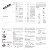
Dimensions and Tank Capacities
Layout View
Dealer Service
• Ask your dealer to explain all systems before taking delivery of your boat.
• Your dealer is your key to service.
• Contact your dealer if you have any problems with your new boat.
• If your dealer cannot help, call our customer service hotline: 360-435-8957 or send us a FAX: 360-403-4235.
• Buy replacement parts from any authorized Bayliner dealer.
Warranty Information
• Bayliner offers a Limited Warranty on each new Bayliner purchased through an authorized Bayliner dealer.
• A copy of the Limited Warranty was included in your owner’s packet.
• If you did not receive a copy of the Limited Warranty, please contact your dealer or call 360-435-8957 for a copy.
Overall
Length
Bridge
Clearance
Beam
Draft
(Drive Up)
Draft (Drive
Down)
Fuel Capacity
(gal)
Freshwater
Capacity (gal.)
Waste Holding
Tank Capacity (gal.)
(If Equipped)
26' 7" 7' 3" 9' 5" 1' 9" 3' 2" 85 31 20
stowage
beneath
folding
transom
seat
stowage
beneath
folding
transom
seat
helm
bench
seat
helm
bench
seat
fold down
SunChaiser
lounge
TM
TM
fold down
SunChaiser
lounge
TM
fold down
SunChaiser
lounge
mid ship
cleats
mid ship
cleats
mid ship
cleats
mid ship
cleats
sinksink w/
stovestove
headhead
stepssteps
transom
door
transom
door
engine
hatch
berth w/
stowage
under
berth w/
stowage
under
quick drop
table
converts
to larger
forward
v-berth
quick drop
table
converts
to larger
forward
v-berth
storage
under
storage
under
storage
under
storage
under
double
mid-berth
double
mid-berth
stowage
stowage
stowage
under
helm
stowage
under
helm
seat
cooler niche
under lounge
cooler niche
under lounge
table
sink
trash in
trash
bin

Chapter 1: Welcome Aboard! 265 • Owner’s Manual Supplement
2
Boating Experience
If this is your first boat or if you are changing to a type of boat you are not familiar with, for your own comfort and
safety, obtain handling and operating experience before assuming command of the boat.
Take one of the boating safety classes offered by the U.S. Power Squadrons or the U.S. Coast Guard Auxiliary.
For more course information, including dates and locations of upcoming classes, contact the organizations directly:
• U.S. Power Squadrons: 1-888-FOR-USPS (1-888-367-8777) or on the Internet at: http://www.usps.org
• U.S. Coast Guard Auxiliary: 1-800-368-5647 or on the Internet at: http://www.cgaux.org
Outside the United States, your selling dealer, national sailing federation or local boat club can advise you of local
sea schools or competent instructors.
Safety Standards
Your boat’s mechanical and electrical systems were designed to meet safety standards in effect at the time it was
built. Some of these standards were mandated by law, all of them were designed to insure your safety, and the safety
of other people, vessels and property.
In addition to this Owner’s Manual Supplement, please read the Cruiser & Yacht Owner’s Manual and all accessory
instructions for important safety standards and hazard information.
CONTROL HAZARD!
A qualified operator must be in control of the boat at all times. DO NOT operate your boat
while under the influence of alcohol or drugs.
WARNING!
!
FALLING and ROTATING PROPELLER HAZARD!
NEVER allow anyone to ride on parts of the boat not designed for
such use.
• Sitting on seat backs, lounging on the forward deck, bow riding,
gunwale riding or occupying the transom platform while underway is especially hazardous
and will cause personal injury or death.
DANGER!
!
ROTATING PROPELLER and CARBON MONOXIDE
POISONING HAZARD!
• NEVER allow anyone to occupy, or hang from, the
back deck or swim platform while the engine(s)
are running.
• Teak surfing, dragging, or water skiing within 20 feet
of a moving watercraft can be fatal.
DANGER!
!
DANGER
PERSONAL SAFETY HAZARD!
Always secure the anchor and other loose objects before getting underway. The anchor and
other items that are not properly secured can come loose when the boat is moving and cause
personal injury or death.
DANGER!
!

265 • Owner’s Manual Supplement Chapter 1: Welcome Aboard!
3
Engine & Accessory Guidelines
• Your boat’s engines and accessories were selected to provide optimum performance and service.
• Installing different engines or other accessories may cause unwanted handling characteristics.
• Should you choose to install different engines or to add accessories that will affect the boat’s running trim, have an
experienced marine technician perform a safety inspection and handling test before operating your boat again.
• Certain modifications to boat will result in the cancellation of your warranty protection. Always check with
your dealer before making any modifications to your boat.
Engine & Accessory Literature
• The engines and accessories installed on your boat come with their own operation and maintenance manuals.
• Read and understand these manuals before using the engines and accessories.
• Unless noted otherwise, all engine and accessory literature referred to in this Owner’s Manual Supplement is
included in your owner’s packet.
Qualified Maintenance
Failure to maintain your boat’s systems (listed in the warning above) as designed could violate the laws in your
jurisdiction and could expose you and other people to the danger of bodily injury or accidental death. Follow the
instructions provided in the Cruiser & Yacht Owner’s Manual, this Owner’s Manual Supplement, the engine owner’s
manual and all accessory instruction sheets/manuals included in your boat’s owner’s packet.
Structural Limitations
The transom platform and bow platform are designed to be lightweight for proper boat balance. The load limit for
these platforms is 30 pounds per square foot, evenly distributed.
When storing your boat please refer to your engine’s operation and maintenance manuals.
NOTICE
To maintain the integrity and safety of your boat, allow only qualified personnel to perform
maintenance on, or in any way modify: The steering system, propulsion system, engine control
system, fuel system, environmental control system, electrical system or navigational system.
WARNING!
!

Chapter 1: Welcome Aboard! 265 • Owner’s Manual Supplement
4
Special Care For Moored Boats
• Whether moored in saltwater or freshwater, your boat will collect marine growth on its hull bottom.
• This will detract from the boat’s beauty, greatly affect its performance and may damage the gelcoat.
• There are two methods of slowing marine growth:
1. Periodically haul the boat out of the water and scrub the hull bottom with a bristle brush and a solution
of soap and water.
2. Occasionally re-paint the hull below the waterline with a good grade of anti-fouling paint.
Sacrificial Anodes (Zincs)
Your boat is equipped with sacrificial anodes (zincs) to protect underwater metal parts from excessive deterioration.
Check zincs regularly and replace them if they have deteriorated more than 70%.
There are many factors that determine the rate at which zincs deteriorate, including:
• Water temperature
• Salinity
• Water pollution
Stray current from the boat or dock may cause complete deterioration in just a few weeks. If there is rapid zinc
deterioration, measure the electrolytic corrosion around your boat with a Corrosion Test Meter. If the zincs are not
bonded correctly, they will not provide protection.
NOTICE
• To help seal the hull bottom and reduce the possibility of gelcoat blistering on moored boats,
apply an epoxy barrier coating. The barrier coating should be covered with several coats of
anti-fouling paint.
• Many states regulate the chemical content of bottom paints in order to meet environmental
standards. Check with your local dealer about recommended bottom paints, and about the
laws in effect in your area.
Do not paint between the zinc and the metal surface it contacts and do not paint over the zincs.
NOTICE
NEW SACRIFICIAL ANODE DETERIORATED SACRIFICIAL ANODE

265 • Owner’s Manual Supplement Chapter 1: Welcome Aboard!
5
Boat Lifting
• Always follow the lift equipment’s instructions and requirements.
• If there is water in the bilge, pump or drain the water out of the bilge before lifting your boat. Water in the bilge
can shift and change the balance of the load.
Sling Placement
• When lifting your boat, always position the lifting slings at the port and starboard sling label positions as shown in
the illustration above.
PERSONAL INJURY and /or PRODUCT OR PROPERTY DAMAGE HAZARD!
• Lifting slings may slip on the hull. Avoid serious injury or death by securing the slings
together before lifting.
WARNING!
!
PRODUCT OR PROPERTY DAMAGE HAZARD!
• When lifting any boat, always use a spreader bar. The spreader bar must be equal to the
width of the boat at the lifting point.
CAUTION!
!
3 1/2" 42 1/2"
AFT SLING
POSITION
FORWARD
SLING POSITION
C
L
C
L
C
L
NOTE:LIFTING SLING LABEL LOCATIONS
(TYPICAL PORT & STARBOARD)

Chapter 1: Welcome Aboard! 265 • Owner’s Manual Supplement
6
Carbon Monoxide (CO)
Facts about CO
• CO poisoning causes a significant number of boating deaths each year.
• Called the "silent killer", CO is an extremely toxic, colorless, odorless and tasteless gas.
• CO can harm or even kill you inside or outside your boat.
• CO can affect you whether you’re underway, moored, or anchored.
• CO symptoms are similar to seasickness or alcohol intoxication.
• CO can make you sick in seconds. In high enough concentrations, even a few breaths can be fatal.
• Breathing CO blocks the ability of your blood to carry oxygen.
• The effects are cumulative, even low levels of exposure can result in injury or death.
Factors That Increase the Effects of CO Poisoning
• Age
• Smokers or people exposed to high concentrations of cigarette smoke
• Consumption of alcohol
• Lung disorders
• Heart problems
• Pregnancy
• Carbon monoxide gas (CO) is colorless, odorless, tasteless, and
extremely dangerous.
• All engines, generators, and fuel burning appliances produce CO
as exhaust.
• Prolonged exposure to low concentrations or very quick exposure to
high concentrations will cause BRAIN DAMAGE or DEATH.
• Teak surfing, dragging, or water skiing within 20 feet of a moving
watercraft can be fatal.
DANGER!
!

265 • Owner’s Manual Supplement Chapter 1: Welcome Aboard!
7
Where and How CO Can Accumulate
Stationary Conditions That Increase CO Accumulations Include:
To correct stationary situations A and/or B:
• Close all windows, portlights and hatches.
• If possible, move your boat away from source of CO.
Running Conditions That Increase CO Accumulations Include:
To correct running situations C and/or D:
• Trim bow down.
• Open windows and canvas.
• When possible, run boat so that prevailing winds help dissipate exhaust.
How to Protect Yourself and Others From CO
• Know where and how CO may accumulate in and around your boat (see above).
• Maintain fresh air circulation throughout the boat at all times.
• Know where your engine and generator exhaust outlets are located and keep everyone away from these areas.
• Never sit on, or hang onto, the back deck or swim platform while the engine(s) are running.
• Never enter the areas under swim platforms where exhaust outlets are located.
• Although CO can be present without the smell of exhaust fumes, if exhaust fumes are detected on the boat, take
immediate action to dissipate these fumes.
• Treat symptoms of seasickness as possible CO poisoning. Get the person into fresh air immediately. Seek medi-
cal attention—unless you’re sure it’s not CO.
• Install and maintain CO alarms inside your boat. Do not ignore any alarm. Replace alarms as recommended by
the alarm manufacturer.
• Follow the checklists provided on the next page.
• Get a Vessel Safety Check.
For information on how to get a free VESSEL SAFETY CHECK, visit www.vesselsafetycheck.org or contact your
local U.S. Coast Guard Auxiliary or United States Power Squadrons®.
• U.S. Coast Guard Auxiliary: 1-800-368-5647 or on the Internet at: http://www.cgaux.org
• U.S. Power Squadrons: 1-888-FOR-USPS (1-888-367-8777) or on the Internet at: http://www.usps.org
A. Using engine,
generator, or
other fuel burn-
ing device
when boat is
moored in a
confined space.
B. Mooring too close to another boat that is using its
engine, generator, or other fuel burning device.
C. Running boat with trim angle of bow too high.
D. Running boat without through ventilation (sta-
tion wagon effect).

Chapter 1: Welcome Aboard! 265 • Owner’s Manual Supplement
8
Trip Checklist
❏ Make sure you know where the exhaust outlets are located on your boat.
❏ Educate all passengers about the symptoms of CO poisoning and where CO may accumulate.
❏ When docked, or rafted with another boat, be aware of exhaust emissions from the other boat.
❏ Confirm that water flows from the exhaust outlet when the engines and generator are started.
❏ Listen for any change in exhaust sound, which could indicate an exhaust component failure.
❏ Test the operation of each CO alarm by pressing the test button.
Monthly Checklist
❏ Make sure all exhaust clamps are in place and secure.
❏ Look for exhaust leaking from exhaust system components. Signs include rust and/or black streaking, water
leaks, or corroded or cracked fittings.
❏ Inspect rubber exhaust hoses for burned, cracked, or deteriorated sections. All rubber hoses should be pliable and
free of kinks.
Annual Checklist
Have a Qualified Marine Technician:
❏ Replace exhaust hoses if cracking, charring, or deterioration is found.
❏ Ensure that your engines and generators are properly tuned, and well maintained.
❏ Inspect each water pump impeller and the water pump housing. Replace if worn. Make sure cooling systems are
in working condition.
❏ Inspect all metal exhaust parts for cracking, rusting, leaking, or loosening and check the cylinder head gasket,
exhaust manifold, water injection elbow, and the threaded adapter nipple between the manifold and the elbow.
❏ Clean, inspect, and confirm proper operation of the generator cooling water anti-siphon valve (if equipped).
Carbon Monoxide Alarm System
• Your boat features a carbon monoxide (CO) alarm system.
• Do not disconnect the alarm system.
• Read and understand the manufacturer’s instructions for your CO alarm system. If you did not receive an
instruction manual, call (800) 383-0269 and one will be mailed to you.
If your boat is not equipped with a carbon monoxide alarm, consider purchasing one from your dealer or marine
supply store.
CARBON MONOXIDE POISONING HAZARD!
• The house battery switch must be in the On position for the CO Monitors
to work.
DANGER!
!
The stereo memory and CO monitor(s) place a small, but constant drain on the battery. If your
boat will be unattended for an extended amount of time, plug into shore power with the battery
charger turned On, or disconnect the battery if shore power is not an option.
NOTICE

265 • Owner’s Manual Supplement Chapter 1: Welcome Aboard!
9
More Information
For more information about how you can prevent carbon monoxide poisoning on recreational boats and other ways to
boat more safely, contact:
For information on how to get a free VESSEL SAFETY CHECK, visit www.vesselsafetycheck.org or contact your
local U.S. Coast Guard Auxiliary or United States Power Squadrons®.
• U.S. Coast Guard Auxiliary: 1-800-368-5647 or on the Internet at: http://www.cgaux.org
• U.S. Power Squadrons: 1-888-FOR-USPS (1-888-367-8777) or on the Internet at: http://www.usps.org
United States Coast Guard
Office of Boating Safety (G-OPB-3)
2100 Second Street SW
Washington, DC 20593
www.uscgboating.org
1-800-368-5647
National Marine Manufacturers
Association (NMMA)
200 East Randolph Drive
Suite 5100
Chicago, IL 60601-9301
www.nmma.org
312-946-6200
American Boat & Yacht Council,
Inc. (ABYC)
3069 Solomon’s Island Road
Edgewater, MD 21037-1416
www.abycinc.org
410-956-1050

10
265 • Owner’s Manual Supplement
Chapter 2: Features / Systems
Hull Hardware
WATER TANK
ANCHOR
LOCKER
GALLEY
DRAIN
OVERBOARD
(IF EQUIPPED)
AIR CONDITIONING
DRAIN
(IF EQUIPPED)
COCKPIT
DRAINS
DRAIN
BOW EYE
PORT HULLSIDE
STARBOARD HULLSIDE
SHOWER
SUMP
HEAD
SINK
FWD BILGE
PUMP
AFT BILGE
PUMP
FUEL AND
WASTE TANK VENTS
STORAGE
DRAIN
COCKPIT
DRAINS
VENT
AIR CONDITIONING
GARBOARD
DRAIN
MACERATOR
DISCHARGE (IF EQUIPPED)
RETRACTABLE
BOARDING LADDER
STERN EYESTRIM TAB
(TYPICAL)
TRANSOM

265 • Owner’s Manual Supplement Chapter 2: Features / Systems
11
Deck Hardware
Anchor Windlass (If Equipped)
Your boat may feature an anchor
windlass. Read the manufacturer’s
instruction manual supplied in your
boat’s owner’s packet before using
the anchor windlass for the first time.
• The windlass can be controlled from
a switch at the helm or from the deck
switches (see illustration to right).
• Make sure that the windlass breaker,
located under the aft cockpit enter-
tainment center sink, is turned On
before using the anchor windlass.
• To haul the anchor, use engine power
(not the windlass) to move the boat
to, and directly above, the anchor.
• Use the windlass to disengage the
anchor from the bottom by pulling
it straight up.
WASTE
PUMP-OUT
DECK
CLEAT
FITTING
GRAB
HANDLES
WATER
FILL
AFT
AFT DECK HARDWARE
FWD
FUEL
FILL
FORWARD DECK HARDWARE
(TYPICAL)
ANCHORBOW ROPE CHOCK
ROLLERCLEAT (TYPICAL)
NAVIGATION
LIGHT (TYPICAL)
VIEW OF FORWARD DECK
ROPE
CHOCK
NAVIGATIONAL
LIGHT
WINDLASS “DOWN”
SWITCH
ANCHOR
WINDLASS
ANCHOR ROLLER
FWD
WINDLASS “UP”
SWITCH
CAUTION!
PRODUCT DAMAGE HAZARD!
Do not pull the boat to the anchor using the windlass or continue to use the windlass if it has stalled or
is overloaded.
!

Chapter 2: Features / Systems 265 • Owner’s Manual Supplement
12
Helm
ACCESSORY
SWITCHES
BLOWER
SWITCH
IGNITION
FWD & AFT
BILGE PUMP
SWITCHES
HORN
SWITCH
TRIM TAB
SWITCHES
COCKPIT
LIGHTS
VHF RADIO
ANCHOR
LIGHTS
NAVIGATION
LIGHTS
WIPER
SWITCH
ACCESSORY SWITCH PANEL
FUEL GAUGE
VOLTMETER
DEPTH FINDER
(IF EQUIPPED)
TACHOMETEROIL PRESSURE
GAUGE
TEMPERATURE
GAUGE
TRIM TAB
GAUGE
INSTRUMENT PANEL
SPEEDOMETER
TILT
STEERING
WINDLASS
CONTROLS
INSTRUMENT
PANEL
CIRCUIT
BREAKERS
12 VOLT
ACCESSORY
(IF EQUIPPED)
SWITCH
PANEL
(IF EQUIPPED)
OUTLET
(IF EQUIPPED)

265 • Owner’s Manual Supplement Chapter 2: Features / Systems
13
Electrical System
Thoroughly read and understand this section and the electrical sections of the Cruiser & Yacht Owner’s Manual and
all accessory manuals included in your boat owner’s packet. Electrical routing drawings are provided in Chapter 3 of
this supplement, wiring schematics in Chapter 4.
EXTREME FIRE, SHOCK & EXPLOSION HAZARD!
• To minimize the risks of fire and explosion, NEVER install knife switches or other arcing
devices in the fuel compartments.
• NEVER substitute automotive parts for marine parts. Electrical, ignition and fuel system
parts were designed and manufactured to comply with rules and regulations that minimize
risks of fire and explosion.
• DO NOT modify the electrical systems or relevant drawings.
• Have qualified personnel install batteries and/or perform electrical system maintenance.
• Make sure that all battery switches are turned Off before performing any work in the
engine spaces.
DANGER!
!
FIRE & EXPLOSION HAZARD!
• Fuel fumes are heavier than air and will collect in the bilge areas where they can be
accidently ignited.
• Visually and by smell (sniff test), check the engine and fuel compartments for fumes or
accumulation of fuel.
• ALWAYS run the bilge blowers for at least four minutes prior to engine starting, electrical
system maintenance or activation of electrical devices.
• Minimize the danger of fire and explosion by not exposing the batteries to open flame or
sparks. NEVER smoke anywhere near the batteries.
WARNING!
!
SHOCK & ELECTRICAL SYSTEM DAMAGE HAZARD!
NEVER disconnect the battery cables while the engine is running since it can cause
damage to your boat’s electrical system components.
CAUTION
!
Electrical connections are prone to corrosion. To reduce corrosion caused electrical problems,
keep all electrical connections clean and apply a spray-on protectant that is designed to protect
connections from corrosion.
NOTICE

Chapter 2: Features / Systems 265 • Owner’s Manual Supplement
14
12 Volt DC System
Fuses and Circuit Breakers
• The 12 volt DC electrical system is protected by a large circuit breaker located on the engine.
• The accessories are protected by circuit breakers on the battery switch panel and by circuit breakers on the main
circuit breaker panel.
• Some equipment may have additional fuse protection provided by inline fuses near the unit or behind the
battery switch.
12 Volt Accessory Outlets
Your boat is equipped with two 12 volt accessory outlets; one at the helm and one in the galley. These outlets can be
used with any 12 volt device which draws 15 amps or less. The 12 volt accessory outlets are protected by 15 amp
circuit breakers on the main circuit breaker panel.
DC MAIN
FORWARD
BILGE PUMP
AFT BILGE
PUMP
ACCESSORY
MAIN CIRCUIT
BREAKER PANEL
DO NOT use the 12 volt accessory outlets with cigarette or cigar lighters. High temperatures
may melt the outlets.
CAUTION!
!
/