Page is loading ...

1
Website: www.jtechdigital.com
Toll Free: 1-888-610-2818[US]
Email:[email protected]
USER MANUAL
J-Tech Digital
®
ProAV
Multi Inputs Video Wall Controller
JTD-ID:1283
RoHS

2
Dear Customer
Thank you for purchasing this product. For optimum performance and safety, please read
these instructions carefully before connecting, operating or adjusting this product. Please
keep this manual for future reference.
1. FEATURES
Support USB/VGA/Composite/HDMI input.
Select 1 of 4 source and distri bute to 4 displays.
Create a 2x2 Video Wall Controller from any source to four displays.
Support multi-level cascading to create 3x3, 4x4...Video Wall (Max 10x10).
Support 180° rotation.
Support resolution up to 1080p Full HD.
Support Panel control, IR control, RS232 control.
2. NOTICE
Our company reserve the right to make changes in the hardware, packaging and any
accompanying documentation without prior written notice.
3. TABLE OF CONTENTS
Specifications
Package Contents
Panel Descriptions
Connecting and Operating
Typical Application
Remote Control Instruction
RS232 Control
Maintenance
Product Service
Warranty

3
4. SPECIFICATIONS
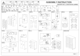
5. PACKING CONTENTS
1) Main Unit: HD Video Wall Controller
2) 1x Power supply 5V4A
3) 4x Screws
4) 2x detachable mounting ears
5) 1x IR Cable
6) 1x Remote controller
7) Operating Instructions
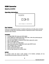
6. PANEL DESCRIPTIONS
Front Panel
1. Output Selection 2. Indicator of Output 3. Power input indicator
4. IR port 5. Up 6. Down
7. Right 8. Left 9. Menu
10. Source Selection 11. Enter 12. Reset
13. Power button
Operating Temperature Range 0 to +35°C (32 to +95°F)
Operating Humidity Range 5 to 90 % RH (no condensation)
Input Video Signal 0.5-1.0 volts p-p
Input DDC Signal 5 volts p-p (TTL)
Video Format Supported
DTV/HDTV: 1080P/1080i/720P/
576P/480P/576i/480i
Audio Format Supported LPCM
Input ports 1xHDMI, 1xUSB, 1xVGA, 1xAV
Output ports 4xHDMI
Splitter mode 1x4 HDMI Splitter
Video wall mode 2x2,3x3,4x4......10x10 video wall
Control Way Panel control, IR control, RS232 control
Power consumption 15watts(Maximun)
Dimension (mm) L380.6XW136.6XH43.5 mm
Weight 1725g

4
Rear Panel
1. Power input port 2. IR Ext port 3. RS232 port
4. USB input port 5. HDMI input port 6. VGA input port
7. Audio input port 8. CVBS input 9. L /R Audio input
10. Audio output 11. HDMI output
Right Panel
1. DIP switch for EDID choosing
000001 Setting for Output1
000010 Setting for Output2
000100 Setting for Output3
001000 Setting for Output4
010000 Turn on Multi-function button “All”
100000 Turn on “Splicing setup” mode
If you need make splicing setup for 4 HDMI outputs, you can set to “001111”
7. CONNECTING AND OPERATING
1) Connect the sources into the video wall controller and Press the button on the remote.
to choose the input Signal (VGA, HDMI, USB, AV input).
2) Connect HDMI OUT to display equipments .
3) Power up the Video Wall Controller.
4) Control the Video Wall Controller by Panel button / DIP Switch / Remote /
RS232 Command.

5
8. Typical Application
Application 1: Split a single source to 4 displays
Application 2: 2x2 Video Wall Displaying
Application 3: Multi-Level Cascading (Max 10x10 Video Wall)

6
9. Remote Control Instruction
1. Power on/off
2. Mute
3. Next one
4. Stop
5. Previous one
6. Play/Stop
7. USB Disk input
8. HDMI input
9. AV input
10. VGA input
11. Menu
12. Multi-function Button
13. Up
14. Left
15. Right
16. Down
17. Mirror on/off
18. Back
19. Output 1 ~ Output 4
20. Splicing on/off
Note 1: is under USB mode.
Note 2: is Multi-function Button.
2.1.Press button “ALL”, the “ALL” indicator will turn green, t hen press “ ” into
the main menu.
2.2 Under USB input mode , press button “ALL ” for all the setting
2.3.Press button “ALL”, then press , to adjust the volume
9.1 Language Setting
9.1.1 The main menu language Settings
1. Press “All” button, the “All” indicator will turn green, then press “ ” to enter into the
main menu.

7
2. Move the left or right arrow, enter into the below interface, choose “OSD Language
English”, then press “Ok”.
3. Choose the required language, then press “OK”, press “ ” back to the main menu.

8
9.1.2 Lan
g
ua
g
e settin
g
for each output
1. Press the Output No on the remote and press “ ”, press “OSD Language” and
choose the
required language
9.2 Mirror Function ( 180°Rotation )
1. Press the Output No on the remote, the press “ ”
2. You can also turn on /off the Mirror function on the menu as below:

9
9.3 Splicing Setup:
1. Press the Output No on the remote or use DIP Switch to choose the output, the relative
indicator will turn green, then press “ ”.
For example, if you need make splicing setup for output 1 to output4, press “1”,”2”,”3”,”4”
on the remote, the indicator “1” to indicator “4” will turn green , then press “ ”.

10
2. Choose “Splicing SETUP”, When the Horizontal Count and Vertical Count is the same,
there will be no deformation on the image.
3. When cascade for NXN video wall , the output which cascade for next layer should be
set as “1x1”, other outputs should be set as your required”NXN”.
For example, if you need cascade for “3x3”, the output 1 need to connect with next Video
Wall Controller , then the output 1 should be set as “1x1”, output2 to output4 should be set
as “3x3”.
4. After setting the Horizontal Count and Vertical Count, press “ ” to turn on /off the
video wall mode
9.4. Menu Reset
Choose “Menu Reset” to res tore factory s etting.

11
9.5. Edge Adjust.

12
9.6 Scroll Text (Support CVBS/VAG/HDMI input modes)
1. Create a text document named “ARICH.TXT” under the USB DISK, enter the required
content in the document.
2. Insert the USB Disk into the USB port of product.
3. Press”All” on the remote or set the DIP Switch to “010000” , then press “ ”.

13
4. Move the left or right arrow to choose “Scroll Text”.
5. Enter “Scroll Text”, you can set the Font size, Background Color, Font color,
Flow Speed.

14
6. Turn on the Function, then re-power the Video Wall controller, there will be scroll text on
the display.
9.7 USB Disk Input Mode
1.Choose USB input , press “ALL” button on the remote controller, then you can select the
required file to play.

15
2.Press “OK” button when playing the video or displaying pictures.

16
3. Support JPG、PNG, BMP format pictures
4. Support MP3, FLAC format audio files.
5. Support AVI.WMV,MPG,MP4,RMVB video files
6. Support TXT format file

17
9.8 CVBS/HDMI input mode
:
You can set as 16:9 or 4:3 in this mode.
9.9 VGA input mode

18
10. RS232 Control
1). Open CommUart Assistant.
2). Comport setting:
Baud
Rate:
115200 bps
Parity: None
Data Bits: 8 bit
Stop Bits: 1 bit
3). Enter Port Command in Send options.

19
Command Features
99 06 FF FF Show Panel no for all HDMI outputs
99 07 FF FF Hide panel no for all HDMI outputs
79 92 FF AV input
79 93 FF VGA input
79 94 FF HDMI input
79 95 FF USB input
All bellowing command is only effective f or the selected output, please choose t he output
before sending command.
79 19 X
Select from output1 to output4 (X: 1-4).
79 1A X Cancel the output
79 1B FF Choose all the outputs
79 1C FF Cancel all the output
79 35 FF Still image
79 36 FF Cancel still image
79 88 FF Image horizontal Stretching
79 89 FF Image horizontal Compression
79 8A FF Image vertical stretching
79 8B FF Image vertical stretching
79 8C FF Panel no +
79 8D FF Panel no -
79 8E FF Splicing on
79 8F FF Splicing off
79 90 FF Mirror on (180°rotation )
79 91 FF Mirror off
69 73 FF Open the menu
69 63 FF Up
69 83 FF Down
69 72 FF Left
69 74 FF Right
69 49 FF Enter
69 48 FF Back
79 10 FF Increase brightness
79 11 FF Decrease brightness
79 48 FF Brightness reset
79 12 FF Increase the contrast
79 13 FF Decrease the contrast
79 49 FF Contrast reset

20
MAINTENANCE
Clean this unit with a soft, dry cloth. Never use alcohol, paint thinner of benzine to clean
this unit.
PRODUCT SERVICE
1) Damage requiring service:
The unit should be serviced by qualified service personnel if:
(a) The DC power supply cord or AC adaptor has been damaged;
(b) Objects or liquids have gotten into the unit;
(c) The unit has been exposed to rain;
(d) The unit does not operate normally or exhibits a marked change in performance;
(e) The unit has been dropped or the cabinet damaged.
1) Servicing Personnel: Do not attempt to service the unit beyond that described in
these operating instructions. Refer all other servicing to authorized servicing personnel.
3) Replacement parts: When parts need replacing ensure the servicer uses parts
specified by the manufacturer or parts that have the same characteristics as the original
parts. Unauthorized substitutes may result in fire, electric shock, or other hazards.
4) Safety check: After repairs or service, ask the servicer to perform safety checks to
confirm that the unit is in proper working condition.
WARRANTY
If your product does not work properly because of a defect in materials or workmanship,
our Company (referred to as "the warrantor" ) will, for the length of the period indicated as
below, (Parts(2)Year, Labor(90) Days) which starts with the date of original purchase
("Limited Warranty period"), at its option either(a) repair your product with new or
refurbished parts, or (b) replace it with a new of a refurbished prod uct. The decision to
repair or replace will be made by the warrantor.
During the "Labor" Limited Warranty period there will be no charge for labor.
During the "Parts" warranty period, there will be no charge for parts. You must mail-in your
product during the warranty period. This Limited Warranty is extended only to the original
purchaser and only covers product purchased as new.Apurchase receipt or other proof of
original purchase date is required for Limited Warranty service.
MAIL-IN SERVICE
When shipping the unit carefully pack and send it prepaid, adequately insured and
preferably in the original carton. Include a letter detailing the complaint and provide a day
time phone and/or email address where you can be reached.
LIMITED WARRANTY LIMITS
A
ND EXCLUSIONS
1) This Limited Warranty ONLY COVERS failures due to defects in materials or
workmanship, and DOES NOT COVER normal wear and tear or cosmetic damage.
The Limited Warranty ALSO DOES NOT COVER damages which occurred in shipment,
or failures which are caused by products not supplied by warrantor, or failures which result
from accidents, misuse, abuse, neglect, mishandling, misapplication, alteration, faulty
installation, set-up adjustments, misadjustment of consumer controls, improper
maintenance, power line surge, lightning damage, modification, or service by anyone
other than a Factory Service center or other Authorized Servicer, or damage that is
attributable to acts of God.
2) THERE ARE NO EXPRESS WARRANTIES EXCEPT AS LISTED UNDER "LIMITED
WARRANTY COVERAGE". THE WARRANTOR IS NOT LIABLE FOR INCIDENTAL OR
CONSEQUENTIAL DAMAGES RESULTING FROM THE USE OF THIS PRODUCT, OR
ARISING OUT OF ANY BREACH OF THIS WARRNTY. (As examples, this excludes
damages for lost time, cost of having someone remove or re-install an installed unit if
applicable, travel to and from the service, loss of or damage to media or images, data or
other recorded content. The i tems listed are not exclusive, but are for illustration only.)
3) PARTS AND SERVICE, WHICH ARE NOT COVERED BY THIS LIMITED WARRANTY,
ARE YOUR RESPONSIBILITY.
/