Page is loading ...

Frymaster, a member of the Commercial Food Equipment Service Association, recommends
using CFESA Certified Technicians.
24-Hour Service Hotline 1-800-551-8633
819-5184
01-00
U.S. Navy Electric Fryers
Installation, Operation, Service and Parts Manual
FPH17, H14/H17/H22, H14 Sub Series
*8195184*

FRYMASTER ELECTRIC FRYERS ARE MANUFACTURED FOR USE WITH THE TYPE
VOLTAGE SPECIFIED ON THE FRYER RATING PLATE LOCATED ON THE FRYER
DOOR. FOR PROPER INSTALLATION PROCEDURES IN THE UNITED STATES,
REFER TO THE LATEST EDITION OF THE NATIONAL ELECTRIC CODE
ANSI/N.F.P.A. NO. 70; IN CANADA, CANADIAN ELECTRICAL CODE PART 1, CSA-22.1.
INFORMATION ON THE CONSTRUCTION AND INSTALLATION OF VENTILATING
HOODS MAY BE OBTAINED FROM THE LATEST EDITION OF THE "STANDARD FOR
THE INSTALLATION OF EQUIPMENT FOR THE REMOVAL OF SMOKE AND
GREASE LADEN VAPORS FROM COMMERCIAL COOKING EQUIPMENT, "N.F.P.A.
NO. 96. COPIES OF THESE ELECTRICAL STANDARDS ARE AVAILABLE FOR THE
NATIONAL FIRE PROTECTION ASSOCIATION, BATTERY MARCH PARK, QUINCY,
MASS. 02269
WARNING
In the event of a power failure, the fryer(s) will automatically shut down. Should this occur, turn
the power switch off. Do not attempt to start the fryer(s) until power is restored.
WARNING!
The front ledge of the fryer is not a step. Do not stand on the fryer. Serious injury can result from
contact with hot oil, slips or falls.
WARNING!
The crumb tray must be emptied into a fireproof container at the end of each day. Some food
particles can spontaneously combust if left in certain shortening.
THE FRYER(S) MUST BE INSTALLED WITH A SIX-INCH (15 cm) CLEARANCE AT BOTH
SIDES AND ADJACENT TO COMBUSTIBLE CONSTRUCTION. A MINIMUM OF 24-
INCHES (60 cm) SHOULD BE PROVIDED AT THE FRONT OF THE FRYER(S) DOOR.
FOR YOUR SAFETY, DO NOT STORE OR USE GASOLINE OR OTHER FLAMMABLE
VAPORS AND LIQUIDS IN THE VICINITY OF THIS OR ANY OTHER APPLIANCE.
THIS MANUAL SHOULD BE KEPT IN A CONVENIENT LOCATION AND REFERRED TO
WHEN ANY PROBLEM OCCURS AND FOR FUTURE REFERENCE.

TABLE OF CONTENTS
Page #
1. PARTS ORDERING/SERVICE INFORMATION 1-1
2. IMPORTANT INFORMATION 2-1
3. INSTALLATION INSTRUCTIONS 3-1
4. ELECTRICAL SERVICE CONNECTIONS 4-1
5. POWER REQUIREMENTS 5-1
6. OPERATING INSTRUCTIONS 6-1
7. DRAINING AND MANUAL FILTERING INSTRUCTIONS 7-1
8. ANALOG CONTROLLERS 8-1
9. TROUBLESHOOTING GUIDE 9-1
10. SERVICE PROCEDURES 10-1
11. PREVENTIVE MAINTENANCE 11-1
12. *FILTRATION (BUILTIN) 12-1
13. *CARE AND CLEANING FILTER SYSTEM 13-1
14. *BUILT-IN FILTRATION TROUBLESHOOTING GUIDE 14-1
15. WIRING DIAGRAMS 15-1
16. PARTS LISTS 16-1
*For FPH17 only

CHAPTER 1: PARTS AND SERVICE INFORMATION
1
Parts orders must be placed directly with your local Frymaster Parts Distributor. A list of Frymaster Parts
Distributors was included with the fryers when shipped from the factory. If you do not have access to this
list, please contact the Frymaster Technical Services Department at 1-800-551-8633 or 1-318-865-1711.
To help speed your order, the following information is required:
Model Number:
Serial Number:
Type of Gas or Voltage:
Part Number:
Service information may be obtained by calling your local Factory Authorized Service Center. A list of
these agencies was packed with your fryer.
Service information may also be obtained by calling the Frymaster Technical Services Department.
When calling, please have the following information available:
Model Number:
Serial Number:
Type of Gas or Voltage:
Nature of Service Problem:
And other information that may be helpful in solving your service problem.
Note: Retain and store this manual in a safe place for future use. Additional copies may be obtained
from the Frymaster Technical Services Department.

CHAPTER 2: IMPORTANT INFORMATION
2-1
2.1. Introduction
The H14, H17, H22 Series are deep-well, single open-pot fryers. FPH14, FPH17, FPH22 filter models
come in single, double, triple, and four-fryer configurations. The H14 for use in submarines is a single
only. Read the instructions in this manual thoroughly before attempting to install, operate or service
this equipment.
2.2. Operating, Installation, and Service Personnel
Operating information for FRYMASTER equipment has been prepared for use by qualified and/or
authorized operating personnel only.
All installation and service on FRYMASTER equipment must be performed by qualified, certified,
licensed, and/or authorized installation or service personnel.
Service may be obtained by contacting your local Factory Authorized Service Center.
2.3. Definitions
Qualified and/or Authorized Operating Personnel
Qualified or authorized operating personnel are those who have carefully read the information in this
manual and have familiarized themselves with the equipment functions or have had previous
experience with the operation of equipment covered in this manual.
Qualified Installation Personnel
Qualified installation personnel are: individuals, a firm, corporation, or a company which either in
person or through a representative are engaged in, and are responsible for the installation of electrical
wiring from the electric meter, main control box, or service outlet to the electrical appliance. Qualified
installation personnel must be experienced in such work, be familiar with all electrical precautions
required, and have complied with all requirements of applicable national, European Community and
local codes.
Qualified Service Personnel
Qualified service personnel are those familiar with FRYMASTER equipment and have been
authorized by THE FRYMASTER CORPORATION. All authorized service personnel are required to
be equipped with a complete set of service parts manuals and stock a minimum amount of parts for
FRYMASTER equipment.
A list of Frymaster Factory Authorized Service Centers is included with the fryer when shipped from
the factory. If you do not have access to this list, please contact the Frymaster Customer Service
Department, using the number listed on the front of this manual. Failure to use qualified service
personnel will void the Frymaster warranty.

CHAPTER 2: IMPORTANT INFORMATION
2-2
2.4. Shipping Damage Claim Procedure
Please note that the FRYMASTER equipment was carefully inspected and packed by skilled personnel
before leaving the factory. The transportation company assumes full responsibility for safe delivery
upon acceptance of the equipment.
What to do if equipment arrives damaged:
1. File claim for damages immediately---regardless of extent of damage.
2. Visible loss or damage---be sure this is noted on the freight bill or express receipt and is signed
by the person making the delivery.
3. Concealed loss or damage---if damage is unnoticed until equipment is unpacked, notify freight
company or carrier immediately and file a concealed damage claim. This should be done within
15 days of date of delivery. Be sure to retain container for inspection.
FRYMASTER DOES NOT ASSUME RESPONSIBILITY FOR DAMAGE OR LOSS
INCURRED IN TRANSIT

CHAPTER 3: INSTALLATION INSTRUCTIONS
3-1
PROPER INSTALLATION IS ESSENTIAL TO EFFICIENT TROUBLE-FREE OPERATION.
ANY ALTERATION OF THE EQUIPMENT VOIDS THE FRYMASTER WARRANTY.
Before installing the newly arrived equipment, inspect it carefully for visible and concealed damage.
See Shipping Damage Claim Procedure, Section 2.4.
3.1 Fryer Leg Information
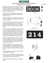
The following drawings give the leg patterns for the FPH17 in two, three and four- vat configurations, which are
commonly placed on ships and the single-vat fryer, which is used on submarines. (See Page 3-3, Sub Fryer
base).
CAUTION
If you need to relocate a fryer installed with legs, remove all the weight from each leg before moving.
If a leg becomes damaged, contact your service agent for immediate repair or replacement.
CAUTION
Any flashing on or around the cap covering the top of the heating elements must be removable.
CAUTION
Prior to installation, make sure the foundation is adequate to secure the fryer front and rear. Depending on
existing conditions, most foundations can be modified to suit the fryer’s base plate.

CHAPTER 3: INSTALLATION INSTRUCTIONS
3-2
27.570 14.400
17.516
32.66
22.68
22.68
33.24
FRONT HANDLE
FPH317
BACK OF FRYER UNIT
7.229
31.61 31.61
35.76
35.76
FRONT HANDLE
FPH417
BACK OF FRYER UNIT
7.119
2.470
17.490
33.45
Mounting Holes
.625
Six Places
62.55
26.320 31.180
7.119

CHAPTER 3: INSTALLATION INSTRUCTIONS
3-3
TYPICAL
7.098
TYPICAL
2.470
BACK OF FRYER UNIT
26.316
17.515
31.45
33.39
31.62
31.62
FRONT HANDLE
FPH217
MOUNTING HOLES
Ø .625
4 PLACES
17.534 6.913
28.29
2.465
10.580
20.48
20.48
33.38
15.67
FRONT HANDLE
H14/17 Single for Surface Ship
BACK
OF
FRYER UNIT

CHAPTER 3: INSTALLATION INSTRUCTIONS
3-4
If it is necessary to install legs, use the instructions provided in the accessories package shipped with
the fryer.
Note:
In most
cases, the
contactor box
in a Sub Fryer
will have to be
removed to
secure
baseplate to
existing
foundation.
Note:
If nut cannot be secured to bolt
from deck, the hole will have to be
drilled and tapped.
25.00
22.00 1.37
1.50
12.00
25.06
25.06
15.00
Navy Sub Fryer
FRONT
MOUNTING HOLES
Ø.375
4 PLACES

CHAPTER 4: ELECTRICAL SERVICE CONNECTIONS
4-1
Connections should be made by means of an approved, flexible-metallic or rubber-covered electrical
cable and quick-disconnect plug. The fryers may be installed with “hard-wired” connections, but use
of quick-disconnect plugs will facilitate service if required. This connection should be made to the
fryer power input terminal block. The terminal block is located in the contactor box in the bottom of
the fryer. CONNECTIONS MUST BE MADE BY QUALIFIED PERSONNEL ONLY AND MEET
NATIONAL AND LOCAL CODES
CAUTION
The fryer(s) MUST be connected to the voltage and phase as specified on the rating and serial number
plate located on the fryer door. To determine the proper wire size and amperage service per fryer, use
the chart on the next page.
CAUTION
A ground wire MUST be connected to the GROUND terminal near the input power terminal block.
CAUTION
Note the following before connecting the fryer to an emergency cutoff system:
• Be sure that each fryer is connected to a dedicated set of contacts in the emergency cutoff system.
• Do not attempt to connect the contacts in series.
• Do not connect more than one fryer to each set of contacts.
• The contacts MUST BE normally closed contacts that open during the emergency.
• The contacts CANNOT have an external voltage applied.

CHAPTER 5: POWER REQUIREMENTS
5-1
WARNING
For power supply connection, use copper wire only, suitable for at least 167°F(75°C).
MODEL VOLTAGE PHASE
WIRE
SERVICE
MIN.
SIZE
AWG
(mm
2
)
AMPS PER LEG
L1 L2 L3
H14 440 3 3 8 (10) 19 19 19
H14 (Sub) 440 3 3 8 (10) 19 19 19
H14 480 3 3 8 (10) 17 17 17
H17 440 3 3 6 (16) 23 23 23
H17 480 3 3 6 (16) 21 21 21
H22 440 3 3 6 (16) 29 29 29
H22 480 3 3 6 (16) 27 27 27
The FPH17 fryer is equipped with a filter system, which requires 120VAC, 20 amp service. The filter-
equipped fryer also has these power requirements per vat:
MODEL VOLTAGE PHASE
WIRE
SERVICE
MIN.
SIZE
AWG
(mm
2
)
AMPS PER LEG
L1 L2 L3
FPH*17 480 3 3 6 (16) 21 21 21
Filter 120 1 3 Standard cord 20
* Denotes number of vats. For example, an FPH317 has three vats.
The electrical power supply for the fryers MUST be the same as the voltage
indicated on the rating and serial number plate located on the fryer door.

CHAPTER 6: OPERATING INSTRUCTIONS
6-1
6.1. After Fryer(S) Have Been Installed At Frying Station:
NOTE: If you need to relocate a fryer installed with legs, remove all the weight from each leg before
moving. If a leg becomes damaged, contact your service agent for immediate repair or
replacement.
1. Close fryer drain valve(s) and fill frypot with water to the bottom oil level line on the rear wall of
vessel.
2. Boil out frypot(s). See Boil Out instructions on this page.
3. Drain, clean, and fill frypot(s) with cooking oil. See Section 6.3, Filling With Shortening.
4. Check thermostat calibration on fryers with solid-state controller.
6.2 Boiling Out The Frypot:
WARNING
Never run water through built-in filtration system
Clean frypot(s) as follows before filling with cooking oil for the first time and
at least once a month thereafter:
1. Before switching the fryer(s) ON, close the frypot drain valve(s), fill empty frypot with mixture of
cold water and Frymaster Fryer 'N' Griddle Cleaner. Other heavy-duty low sudsing degreaser
compounds may also be used. Follow instructions on bottle when mixing.
2. Press fryer ON/OFF switch to the ON position.
3. Set thermostat knob to 200°F (93°C).
4. Allow the solution to simmer for 45 minutes to one hour. Do not permit the water level to drop
below the bottom oil-level line in frypot during boil-out operation.
5. Carefully monitor the fryer during this time to prevent solution from boiling over.
CAUTION
Do not leave fryer unattended. The boil out solution may foam and overflow if fryer is left unattended.
Press ON/OFF switch to the OFF position to control this condition.
6. Turn the fryer ON/OFF switch(es) to the OFF position.

CHAPTER 6: OPERATING INSTRUCTIONS
6-2
7. Add sufficient cold water to lower temperature to a safe level. Drain out the solution and clean the
frypot(s) thoroughly.
8. Refill the frypot(s) with clean water. Rinse the frypot(s) twice, drain and dry inside of pot
thoroughly to remove all residual water.
CAUTION
All drops of water must be removed from frypot before filling with cooking oil.
6.3 Filling With Cooking Oil
Note: Cooking oil/shortening capacity of H14, H17, and H22 Series fryers is 50 lbs. (25 liters) at
70°F (21°C). The capacity of the H14 Submarine fryer is 47 pounds.
Before filling the frypot(s) with cooking oil/shortening:
1. Close the frypot drain valve.
2. Place the power switch(es) to the OFF position.
3. Remove the basket support rack..
4. Fill the empty frypot(s) to the bottom oil-level line.
5. Replace the basket support rack on top of the heating element.
6. Place the ON/OFF switch to the ON position.
7. Set the controller for normal cooking temperature.

CHAPTER 6: OPERATING INSTRUCTIONS
6-3
6.4 Before Relocating Fryer for Service
WARNING
Moving a fryer filled with hot cooking oil may cause splattering. Extreme care must be
exercised. It is recommended that the operator or servicer follow the draining instructions of
this manual before attempting to relocate the fryer for service.
If you need to relocate a fryer installed with legs, remove all the weight from each leg before moving.
If a leg becomes damaged during movement, contact your service agent for immediate
repair/replacement.
1. Turn off fryer controller. Disconnect the electrical power from the source.
2. Relocate the fryer for service accessibility.
3. After servicing is complete, return the fryer to the operating position. Reconnect all electrical
power into source. Secure fryers into position. Refill fryer and resume use.
6.5 Shutting Fryer(S) Off
1. Press fryer controller ON/OFF switch(es) to OFF position.
2. Put frypot cover(s) in place over frypot(s).

CHAPTER 6: OPERATING INSTRUCTIONS
6-4
6.6 Testing Dual Hi-Limit Controls
Note: Perform this test before replacing old shortening. This high temperature test will greatly
reduce life of new shortening. Start test with the fryer turned ON and with the oil at normal
frying temperature. Stir the oil thoroughly to ensure even distribution and temperature and
place a pyrometer sensing probe in center of frypot about one-inch deep. When verifying oil
temperature, use a pyrometer indicating 0-600
0
F and a pryometer sensor probe. A high
temperature thermometer may be used instead of a pyrometer.
CAUTION
If the result listed for each step does not occur, turn off fryer at the main circuit breaker panel and do
not use the fryer. Call service agency.
To test the high limit thermostats, proceed as follows:
STEP 1: Press the hi-limit test switch to the 1
st
hi-limit switch and hold in that position until the
trouble light comes on. The trouble light should come in between 410
0
F + or - 3
0
F, and
the heating elements must shut off. The HEAT light goes out and the TROUBLE light
comes on. Release the test switch.
STEP 2: Press the hi-limit test switch to the 2
nd
hi-limit position and hold in that position until the
2
nd
hi-limit light comes on. It should illuminate between 430°F and 460°F, and the heating
elements must shut off. Release the test switch. All fryers connected to the external shunt
power supply will be shut off completely and all control panel lights will be extinguished.
For fryers not connected to an external shunt power supply, the 2
nd
hi-limit light will come
on and the fryer will shut off.
STEP 3: Turn power switch to the OFF position.
STEP 3: Allow the cooking oil to cool to below normal frying temperature. When the power switch
is again turned ON, the heaters will turn on and the operating thermostat will resume
control of the temperature. If the red trouble light remains on instead, allow the oil
additional time to cool.

CHAPTER 7: DRAINING AND MANUAL FILTERING
7-1
WARNING
Use care when draining and filtering cooking oil/shortening to avoid serious burns.
7.1 Filtering
If you are using a filter other than a FRYMASTER built-in filter system, consult the filter unit
manufacturer’s operating instructions for the recommended procedures. Instructions for using the
FRYMASTER Footprint systems are included in Chapter 16 of this manual.
7.1.a Manual Filtering
The following procedure is recommended to drain and filter your cooking oil/shortening when a filter
machine is not available:
1. Turn the fryer controller power switch to the OFF position. Screw the drain extension pipe
(provided with the fryer) tightly into the drain valve. Make sure the curved end of the tube is
pointing down.
2. Position a metal container with sealable cover under the drain pipe. The metal container must be
able to withstand the hot cooking oil and other hot liquids and be of sufficient capacity to hold
the contents of the frypot. Frymaster recommends that a Frymaster filter cone holder and filter
cone be used when a filter machine is not available. If you are using the Frymaster filter cone
holder and cone, be sure the filter holder rests firmly on the metal container.
3. Open the drain valve slowly to avoid splattering. If splattering occurs, exercise extreme caution.
4. If the drain valve becomes clogged with food particles, use the Fryer’s Friend (poker-like tool).
Use this tool from inside of the frypot ONLY. Grip the tool on the handle as far as possible
from the hot shortening in the frypot. DO NOT HAMMER ON THE DRAIN VALVE, as this
will damage the drain valve ball.
WARNING
Never run water through built-in filtration system.
DANGER
Do not insert the tool into the front of the drain valve to unclog the valve. Hot oil will rush out,
creating an extreme burn hazard!
CAUTION
Allow the shortening to cool to 100°F (38°) or lower before transporting the container and removing
the drain pipe. Exposure to oil at temperatures above 140°F (60°C) can result in severe burns.
5. After draining the oil/shortening, clean all food particles and residual oil/shortening from the
frypot before refilling.
6. Close the drain valve and refill the frypot with clean (or filtered) oil/shortening.

CHAPTER 8: NAVY SHIPBOARD CONTROLLER
8-1
ITEM NO.
1. Power Supply Switch - controls power supply.
2. Power On Light - indicates when electrical power is on.
3. Temperature Control Knob - sets desired frying temperature.
4. Heating Light - indicates element is on.
5. Trouble Light - indicates malfunction of fryer control circuit or overheat condition. Reset by
turning the ON/OFF switch OFF for 30 seconds, then ON.
6. Second High-Limit Light – indicates fryer has overheated and the high limit has shut fryer off.
7. High-Limit Test Switch – Tests high-limit thermostats.
CAUTION
Fryer must be filled with oil, shortening, or water before turning on controller.
8.1 Temperature Calibration
1. Insert a good grade thermometer or pyrometer probe into the cooking oil/shortening near the fryer
temperature-sensing probe.
2. Turn thermostat knob to frying temperature.
3. Let elements cycle on and off automatically three times to allow the cooking oil temperature to be
uniform.
4. When the elements start for the fourth time, the pyrometer reading should be within 5°F (2°C) of
the thermostat knob setting. If it is not, calibrate as follows:
a. Loosen set screw in thermostat control knob until outer shell of knob will rotate on insert inside
knob.
b. Rotate outer shell of knob until index line on knob aligns with marking that corresponds to
thermometer or pyrometer reading.
c. Hold knob and tighten set screw.
OFF
2
ND
POWER
ON
1
ST
HI LIMIT
TEST
POWER
SECOND
TROUBLEHEAT
280
260
220
240
320
300
340
360
200
140
110
100
120
130
150
160
170
180
190
C
F
5
3
7
6
4
2
1
Fig. 8-1

CHAPTER 8: NAVY SHIPBOARD CONTROLLER
8-2
d. Recheck the thermometer or pyrometer reading and the thermostat knob setting the next time
the elements come on.
e. Repeat Steps 4.a. through 4.d. until thermometer or pyrometer reading and knob setting agree
within 5°F (2°C).
f. If calibration cannot be obtained for any reason, call a Factory Authorized Service Center.
5. Remove thermometer or pyrometer probe.
8.2 Hi-Limit tests
Hi-limit 1 checks the ability of the fryer’s controller to shut down
the fryer.
The test is conducted with the oil at or near operating temperature.
Hold the Hi-limit rocker switch in the 1st
position.
The oil will heat to 410
0
F +- 3
0
F degrees before the controller stops
calling for heat. The trouble light will illuminate just at the heat
light goes out.
Reset the fryer by turning the unit off and back on at the control
panel.
Hi-Limit 2 checks the ability of the fryer’s mechanical hi-limit
probe to shut down the fryer. To run the test, hold the rocker
switch in the 2nd position. With the rocker depressed, the oil will
heat to 430-450
0
F degrees before the mechanical hi-limit probe
opens, which shuts off power to the fryer.
Press and hold rocker switch down
for Hi-Limit 1 test. Hold the switch
up for the second hi-limit test.
Fig. 8-2

CHAPTER 9: TROUBLESHOOTING GUIDE
9-1
Directions for Troubleshooting Flow Chart
1. Always start at the first condition and follow each step in sequence.
2. Perform the test set-up at the beginning of each condition.
3. Normal Operation (“yes” after each decision block) flows down the page in sequence.
4. Abnormal Operation (a “no” answer) branches to the right side of the page where you will find the steps
for problem resolution.
Warning:
Inspection, testing and repair of electrical equipment should be performed by qualified service
personnel. Unplug the unit before servicing, except when electrical test are required.
DANGER
USE EXTREME CARE DURING ELECTRICAL CIRCUIT TESTS. LIVE CIRCUITS WILL BE
EXPOSED.
Fryer is Off
Press the ON/OFF
Switch to OFF
Is
CMP light
on
Interface board on?
All other lights
off?
Is
24V Light
on
Interface board on?
Condition is
normal
YES
YES
YES
1. No power applied to fryer from power supply.
2. Defective 12 volt transformer.
3. Defective interface board (12 VAC circuit).
4. Broken or improper wire connection.
5. Blown fuse.
1. Defective 24 volt transformer.
2. Defective interface borard (
24
volt circuit).
3. Broken or improper wire connection.
4. Blown fuse.
1. Defective controller.
2. Improper wire connection.
NO
NO
NO
Using interface board
lights to diagnose fryer.
Note: Access to the interface board is required to
perform troubleshooting. See Figures 10-6 and 10-7.
/