15
7/22/08
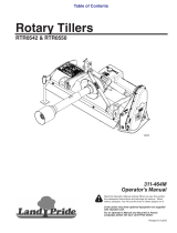
RTR10 & RTR15 Series Rotary Tillers 311-431M
Land Pride
Section 2: Operating
Table of Contents
Parking
Thefollowingsteps shouldbe donewhenpreparingtostore
thetillerorunhitchitfromthetractor.SeealsoStorageinthe
“Maintenance and Lubrication” section on page 22 for
additional information on long term storage of your tiller.
Figure 2-1
1. Reposition the left hand skid shoe (#3) by loosening
bolt(#1) and removingbolt (#2). Pivotskid shoe down
and replace bolt (#2) in the second hole from the top
as shown in Figure 2-1. Tighten bolts (#1 & #2) to the
correct torque. Refer to Torque Values Chart in the
“Appendix” section on page 29.
2. Repeat step #1 for the right hand skid shoe.
3. SeeFigure1-1on page 9. Removeleg stand from the
holder, turn it up right and replace it through the
bottom of the holder.
4. Set legstandto desired height to maintain tiller height
for re-hook-up and install pin to lock in place.
5. Park tiller on a level, solid area.
6. Shut tractor engine off and engage parking brake.
7. Unhitch from tractor.
!
WARNING
Place blocksunder the tiller as needed to prevent it from tipping
over onto a child and/or an adult. A tiller that tips over can
result in injury or death.
8. Check tiller for stability by physically applying
pressureatthehitchplatestoseeifitwilltipforwardor
backwards. If the tiller moves in either direction, then
block under the tiller as needed to prevent that
movement.
22306
IMPORTANT: It is important to adjust the skid shoes
downas shownin Figure 2-1 to stabilizethe tiller when
parked. Always follow “Skid Shoe Adjustment” steps
on page 18 when repositioning the skid shoes.
Operating Instructions
Before using your Land Pride RTR10 or RTR15 Series
Rotary Tiller, you should have completely read the
Operator’s Manual, properly attached the Tiller to the
tractor, cut the driveline to proper length, Run-in the
clutch, and gone through the Operating Checklist. If you
have missed any of these steps, please complete them
before proceeding.
Now that you have properly prepared yourself and your
tiller,it’stime to do sometilling. Carefully drive the tractor
to the site where you intend to till. You should have
already cleaned this site of any large limbs, rocks,
trash, metal or other debris. Best results will be
achievedif youhave mounted yourtiller offsetto the right
far enough to cover the tread of your right tractor wheel.
Linethetractorupjustto therightofcenteronyourtillage
plot. You will be working from the center out and always
turning to the right to line up for your next pass.
Lower the tiller half way to the ground and reduce your
tractor engine speed to about one quarter throttle.
Engage the PTO and gradually increase the engine
speed until you reach full PTO speed of 540 rpm. Lower
the Tiller to the ground and simultaneously commence
forwardtravelof approximately2mph.Donotmaketurns
or attempt to back up while tiller is in the ground. See
important note below.
Travel about 50 ft. and then stop to check your results.
When stopping, remember to lift the tiller out of the
ground, stop the tractor, reduce engine speed,
disengage the PTO, set the park brake, shut off the
tractor, and remove the keys. If youare tilling too shallow
or too deep, adjust the skid shoes accordingly. If the soil
texture is too coarse, lowerthe rear deflector and reduce
your ground speed. If the soil texture is too fine, you will
need to raise your rear deflector and increase your
groundspeed.Foranyotherproblemconditionsthatmay
arise,youwillwanttorefertotheTroubleshootingsection
on page 28.
When you are done tilling for the day, makesure you use
propertractorshutdownprocedures beforeyouget offof
the tractor. If youare detaching your tiller, makesure you
park it on a dry and level surface leaving it clean and
ready for the next use. When you put yourtiller up for the
season,makesureyoureferto theStorageDirections on
page 22.
With a little practiceand afew adjustments, youwill soon
be achieving the results you want with your Land Pride
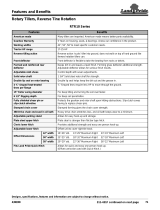
RotaryTiller.See“FeaturesandBenefits”Section6or
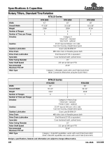
“Specifications and Capacities” Section 5 for
additional information and performance enhancing
options.
IMPORTANT: Turning or backing up with rotary
tines in the ground will damage the tiller.