Page is loading ...

RO-LITE COMMERCIAL SYSTEM INSTALLATION
INSTRUCTION & OWNER’S MANUAL
Ver 2.3
ULTIMATE REVERSE OSMOSIS SYSTEM
All Rights Reserved © APEC Water Systems


Please keep this Owner’s Manual for future reference.
It contains helpful information on how to maintain and care for your
APEC Reverse Osmosis water filter system.

Please read and become familiar with instructions and parts needed before pro-
ceeding with the installation.
BEFORE INSTALLATION:
Inspect the system:
Please take the system and all the components out of the box. Inspect the system and all the connection
fittings carefully, make sure nothing is damaged during shipping. If any part is cracked or broken, please do
not proceed with the installation and contact APEC or your distributor for an exchange or diagnosis.
Recommended tools list:
• Variable speed drill
• Drill bit- 1/4” (for the waste line), 1/8” (as pilot, not mandatory), and 1/2” (for faucet hole, if neces-
sary)
• 5/8”, 9/16” open-end wrench, or adjustable wrench, pliers
• Phillips screwdriver
• Utility knife, or scissors
• Teflon tape
Operating Parameter
• Operating pressure: 85 psi maximum
• Feed water temperature: 40 – 100 degree F (4-37 degree C)
• Do not connect this unit to hot water source
• Protect the RO from freezing. Water freezing in the system will damage it.
• Install the RO in a sheltered environment, avoid exposure to hot and cold weather or under direct
sun light.
Thank you for choosing APEC reverse osmosis systems.
You now own the finest water filter in America.
Copyright:
This manual is copyrighted by APEC Inc. Under the copyright laws, this manual may not be reproduced in
any form, in whole or part, without the prior written consent of APEC Inc.
General Installation/Operation/Maintenance Requirements
• Installation needs to comply with state and local laws and regulations.
• System must be installed indoor away from possible environmental damage
• Do not use with water that is microbiologically unsafe or of unknown quality without
adequate disinfection before or after system. Systems certified for cyst reduction may be
used on disinfected water that may contain filterable cysts.
• This reverse osmosis system contains a replaceable treatment component critical for
effective reduction of total dissolved solids. The product water shall be tested periodically to
verify that system is performing satisfactorily.

1
Components included with the Ro system:
1 RO system 3 Pre-filters in 3 Housings 1 Storage tank 2 - 4 RO membranes
(depends on model)
Pre inserted in
membrane housing
Installation Kit includes
1 Faucet with
washers, nuts and
adapter
1 Feed water adaptor with
feed water ball valve kit
1 Drain saddle for
waste water
Color tubings 3/8” 1 Tank shut-off valve with
adaptor fitting
1 Wrench to open 3
pre-filter housing
1 Wrench to open
membrane housings

2
Component Itemization:
#1) Bracket
#2) Membranes inside their housings
#3) In-line carbon filter (last-stage filter)
#4) Sediment pre-filter and housing (1st stage
filter)
#5) Carbon block pre-filter and housing (2nd-
stage filter)
#6) Carbon block pre-filter and housing (3rd-
stage filter)
#7) Storage tank
#8) Tank shut-off valve
#9) ASO
#10) Check valve
#11) T-fitting (Last-stage filter)
#12) Feed water inlet
#13) Filtered water outlet

3
Fitting Types:
The Ro Lite Commercial System comes standard with Quick-Connect (QC) Fittings.
Quick-Connect (QC) Fittings: (no insert, sleeve, or nut), most of the fittings on the RO unit are this type.
To connect: See Fig.1 Push the tubing into the Quick-Connect fitting tightly, gently pull back on the tubing
to make sure connection was secure.
- No inserts, sleeve, or nuts are needed to secure the connection.
- No Teflon tape!
To disconnect: See Fig.1A Push in and hold down on the collet ring around the base of the fitting, then pull
out tubing.
Fig. 1
Fig. 1A

4
INSTALLING THE SYSTEM
*All filters are already pre-installed inside their housings, please follow the installation steps listed
below.
The Ro Lite Commercial system can be installed in any location where there is a cold water supply with suffi-
cient water pressure for your chosen RO model, and an outlet to drain off the waste water generated by the
system. A sheltered environment is recommended to avoid any exposure to hot and cold weather or under
direct sunlight.
Step 1: Feed Water Connection
The Ro system must be connected to the COLD water supply only!
The Ro’s feed water adaptor fits a 1/2” pipe. If you need to cut the pipe, using a qualified plumber is highly
recommended.
The instructions below are for “under-sink” installation.
1. For under-sink hook up: Locate the Cold water supply valve under the sink. Turn OFF the incoming
cold water completely.
Note: If the cold water shut off valve is unable to turn off the water, the main water supply to
the house must be shut off for the installation.
Be sure to use Teflon Tape on all metal connections to prevent leaks!
2. For Flex Line Riser: See Fig. 2A. Loosen nut and separate cold water riser tube from faucet shank.
Gently bend riser tube so that the Feed Water Adapter (Fig.5) fits onto the faucet shank. Fit the new cone
washer provided in the kit onto the riser tube. Connect the riser tube, the feed water adapter, and faucet
shank together and tighten. Use Teflon tape on threaded parts to prevent leaks.
For Solid Copper Riser: See Fig. 2B. Follow the same procedure as for flex line. If the copper riser
cannot bend, then it’s best to replace it with a flex line riser. Then fit the feed water adaptor the same way
as described above. Use Teflon tape to prevent leaks.

5
3. Ball Valve: See Fig. 2 Screw the Ball Valve onto the Adapter tightly. Apply 5-6 rounds of Teflon tape
onto Ball Valve before attaching it to the Adapter. (Note: The “cone washer” is not needed if your water
line already has a built in washer).
To Open Ball valve: Turn Handle to the horizontal position.
To Close Ball valve: Turn Handle to the vertical position.
Fig. 2
Fig. 2A
Fig. 2B
Fig. 2C
Fig. 2D
Riser
Tube
For Flexible Line
Faucet
Shank
Main Water
Supply
Shut-off
Valve
Riser
Tube
For Solid Line
Faucet
Shank
Feed Water
Adaptor
Feed Water
Adaptor
Main Wate
r
Supply
Shut-off
Valve
Sink
Sink

6
4. Test for leaks at this point: Close the Ball Valve by turning the “handle” to the vertical position, this will
shut-off the feed water. Then, turn ON the cold water supply, watch to see if there is water leaking at the
connection. If there is leakage, re-examine the connection and try applying more Teflon tape or more
tightening at the connections.
Ball Valve: The Feed Water Ball Valve allows you to shut-off feed water to the RO system without shut-
ting off the cold water supply to your sink. When installation is complete, please remember
to Open the Ball Valve to let the feed water through. To open valve: Turn the “handle” to the
horizontal position.
Step 2: Drain Saddle Installation
Note: To avoid annoying drainage noise, mount drain line as low as possible on the vertical tailpiece, or on
horizontal tailpiece.
There is constant water pressure “packed” inside the RO system which blocks the waste water from backing-
up into the system. So the waste water is “forced-drained”, not “gravity-drained”.
1. See Fig. 3. The drain saddle assembly should be installed above the trap and on the vertical or horizon-
tal tailpiece. To reduce the drainage noise, mount the drain line as low as possible above the trap, or on
the horizontal tailpiece.
MOUNT DRAIN
SADDLE AT
EITHER
LOCATION
Fig. 3

7
2. See Fig. 4. Mark the position of the hole on the drain pipe and drill a 1/4” hole through one side of
the drain pipe. There is a piece of self-adhesive sponge provided. Glue this sponge to the inside of the
saddle, this will cushion any gap between the saddle and the pipe. Make sure the hole on the sponge is
thoroughly punched out, and is aligned to the hole on the saddle.
3. See Fig. 4A, 4B. Make sure to align the drain saddle hole to the drilled hole perfectly. Mis-aligning these
two holes will block the waste water and cause membrane damage. Attach the drain saddle to the drain
pipe and tighten the two screws.
Fig. 4
Fig. 4A
Fig. 4B

8
Step 3: Drilling A Hole For The RO Faucet
The RO dispensing faucet can be mounted on the sink, on the counter top, or simply hang at a location
where it’s convenient for you to dispense the filtered water. You will need to drill a hole only if you choose to
mount the faucet on a surface.
If you don’t need the faucet:
If you don’t need to use the faucet and connect the RO’s output directly to your appliance (Icemaker, coffee
maker, soda machines etc.), please make sure your appliance has a shut-off function when it’s full, so that
the RO can shut-off properly. Without an “air-tight” shut off valve at output end, the RO will not shut-off
automatically—it will keep running and quickly deplete the pre-filters and membranes.
Prepare & drill surface for mounting the faucet:
The faucet should be positioned with aesthetics, function and convenience in mind. An ample flat area is
required for the faucet base so that the faucet can be drawn down tightly.
Conditions that may be present which could eliminate the need to drill a hole:
a) If there is an extra hole already in your sink, covered by a chrome cover, then remove the
chrome cover and install the faucet there.
b) If there is a spray hose either not functioning or not desired, then remove the spray hose and
plug the outlet under the main faucet. Be sure to check if the spray uses a diverter at the base
of the spout. If so, remove to avoid trouble later on.
c) If the task of drilling is not a feasible option (i.e. the home is rented, a drill is not available
etc.), then just connect the faucet and hang it on the cabinet door or wherever that is conve-
nient. Be creative!
Safety glasses should be worn to protect your eyes while drilling the faucet hole.
* For best results use a 1/2” carbide-tipped masonry drill bit to drill the hole.
1. Carefully select the faucet location. Make sure the faucet stud will be accessible from below
when the hole is drilled. If space is not available on the upper sink area, the faucet can be lo-
cated on the counter top by the edge of the sink. If the counter top is ceramic tile, the method
for drilling the hole will be the same as for porcelain sinks.
2. For Stainless Steel Sink: Before using a 1/2” carbide drill bit, an indent should be made
with a center punch to keep the drill bit from walking. A small pilot hole will also aid the drill
bit.

9
3. For Porcelain Sink: Porcelain enameled sinks can readily be chipped if care is not exercised
when drilling the hole. Before starting the drill motor, apply firm downward pressure on the
bit until a crunching occurs. This will help keep the drill bit from walking when starting the
hole. A small pilot hole will also aid the drill bit.
Note: Immediately after the hole drilling is done, clean up all metal chips, for metal chips
will stain the porcelain!!
Step 4: Mounting The Faucet
1. Mount the faucet as shown in
Fig. 5 below:
2. Connect the Clear output line to the faucet:
Screw the “Faucet Adapter” (provided) onto the faucet base, as shown in Fig. 5 above. Con-
nect the 3/8” Clear output line to the Faucet Adapter, simply push the line into the Adapter
tightly. NO Teflon tape needed here. (Note: Discard the un-used nut and sleeve in the faucet
kit).
3. 2 ways to dispense water from faucet: Push down on the black lever to fill a glass of water, or
lift up the lever into a locked position to fill a container or to drain the storage tank.
Fig. 5
Black Locating Washer
Lock Washer
Lock Nut
Faucet Adapter
Tubing
Counter Top
Counter Top
Opening
Chrome Base

10
Step 5: Positioning The System
The RO system can stand on the ground or be secured to the wall. The storage tank may be laid on its side
if needed. This position does not affect the tank’s performance. If there is not enough room near the RO
system, you can put the tank away from the system, up to about 20 feet horizontal without much pressure
loss.
Step 6: Connecting The System
There are 4 connections:
Point A to X: Connect RO to COLD water supply- 3/8” Red tubing.
Point G to Y: Connect product water from Last-stage post carbon filter to tank- 3/8” Yellow tubing *.
Point H to Z: Connect product water from Last-stage post carbon filter output to dispensing faucet- 3/8”
Clear tubing.
Drain line to W: Connect waste water line from the RO to drain outlet- 1/4” Black tubing.
* How Tank line works: The line from Point G to Y works as a 2-way line; the Product water enters and
leaves the tank via this same line.
Fig. 6
Make the tubing connections as follows:
To ensure a smooth and correct installation, please connect the water lines in the order outlined below.
Refer to Fig.6 for proper point locations.
Pure Water
Output Faucet
Sample Kitchen
Faucet
Drain Line
Tank Ball Valve
Feed Water
Connect on
Cold Water Line
Drain Saddle
Sample Drain Pipe
Pure Water
Holding Tank
G
Y
H
Z
X
A
W
W
ate
r
F
aucet

11
1. Point Z Faucet connections:
Tubing color: Clear tubing. Connect the 3/8” CLEAR tubing to the base of the RO faucet.
Fitting type: Quick-Connect fitting. No Teflon tape needed here.
2. Point X Feed water connection:
Tubing color: Red tubing. Connect the 3/8” RED tubing to the Feed Water Ball Valve.
Fitting type: Metal compression nut fitting. No Teflon tape needed here.
3. Point W Waste water connection:
Tubing color: Black-tubing. Connect the 1/4” BLACK tubing from the RO to the Drain Saddle.
Fitting type: Quick-Connect fitting on drain saddle. No Teflon tape needed here.
4. Point A System water inlet (to Stage 1 prefilter) connection:
Tubing color: Red tubing. Connect the 3/8” RED tubing from the Feed Water Ball Valve to the RO’s stage 1
pre-filter.
Fitting type: Quick-Connect fitting here. No Teflon tape needed here.
(UV Light: If your RO has a UV light at Stage-0, then connect the Red tubing to the UV light
inlet port).
5. Point H Stage-5 filtered water to faucet connection:
Tubing color: Clear tubing. Connect the 3/8” CLEAR tubing from the faucet base to the last stage post
carbon filter’s outflow end at point H. (See “Flow ” arrow on the filter for flow direction).
Note: Remove the “end plugs” from the filter to open up the ports.
Fitting type: Quick-Connect fitting. No Teflon tape needed here.
(UV Light: If your RO has a UV light at the last stage, then connect the Clear tubing from the
UV outlet port to the RO dispense faucet).
6. Point G Last Stage Post Carbon filter’s T-fitting connection:
Tubing color: Yellow tubing. Connect the 3/8” YELLOW tubing to last stage filter’s T-fitting.
Fitting type: Quick-Connect fitting (remove protective “end plug” from the T-Fitting to open the port).

12
7. Point Y Tank’s input & output connection:
Tank Shut-Off Valve Kit: The tank-shut off kit includes 2 parts. A Shut-off valve and a Tank Output Adap-
tor. They are NOT tightened when we ship out the tank. At this point, wrap Teflon tape onto threaded parts
on the tank adaptor. Put the 2 parts together and tighten them to secure no-leak connection. Please do not
over-tighten for it may crack the plastic shut-off valve!
Put Valve onto Tank: Apply 5-6 wraps of Teflon tape on the tank’s threaded metal stem. Screw the tank
valve onto the tank’s stem, as shown in Fig.7 above.
Connect tank line: Connect the 3/8” yellow tubing from Stage-5 T-fitting to tank’s valve.
Option: Feeding a 2nd Outlet
If you want to connect product water from the RO to a 2nd outlet, you will need:
• One 3/8” T-fitting, preferably the quick-connect type fitting.
• Extra 3/8” tubing long enough to go from the RO system to your 2nd outlet
• Optional: One 3/8” shut-off valve, preferably the quick-connect type.
Before connecting the output water line from Point Z to H, add a T-fitting near point H (see Fig.6A) to divert
product water to both the faucet and your 2nd output point.
Fig. 7
Fig.6A
Pure Water
Output Faucet
Tank Ball Valve
Drain Saddle
Pure Water
Holding Tank
G
Y
H
Z
X
A
W
Water
Fa
uc
e
Tee Fitting to
second output
Ball Valve
(Recommended)

13
Step 7: System Start-Up
1. Turn on feed water: Slowly, turn on your cold water supply. Open the Feed Water Ball
Valve to allow the raw water to enter the system. Turn the “handle” to the horizontal position.
Check for leaks!
2. Turn on tank valve: Turn on the tank’s ball valve to allow water to enter the tank. The tank’s
valve is “On” when the valve lever is parallel (in the same direction) with the valve’s outlet
(see Fig.7). Check for leaks!
3. Wait for tank to fill: Before usage, allow the tank to fill. It takes 2-3 hours to fill tank de-
pending on the incoming water pressure.
4. Drain Tank: Do not use the first tank of water! Drain it out to flush the system and
new filters. Lift the faucet lever up into a locked position to drain tank. Let the tank refill
again and the pure water is ready for use.
5. Clean up area: Allow the system to run while cleaning up tools and work area.
6. Check for leaks! Make sure no water is leaking at joints, fittings, valves, and tubing con-
nections.
Congratulations! You have successfully installed the Reverse Osmosis System.
*** End of Installation Section ***

14
FILTER CHANGE SCHEDULE
The system requires very little maintenance. Just change the filter cartridges regularly as suggested below.
Keep the system sheltered from the weather elements, and run the system within its reasonable output ca-
pacity (i.e. allow the system to rest a few hours a day).
Stages-1,2,3 Pre-filters:
City water usage: Replace the pre-filters at least once a year (annually), or about 8000 gallons of filtered
water produced, whichever comes first.
Well water usage: Replace the pre-filters every 6-8 months depending on well water quality.
Stage-4 Membrane: City Water: Replace every 3-5 years depending on input water quality, water usage,
and prefilter change maintenance.
Private Well Water: Replace every 2-3 years depending on well water quality, and
pre-filter change maintenance.
Membranes Replacement: (2 to 4 membranes depending on RO model)
Lite-180gpd Model: Two 90gpd membranes, replace both together.
Lite-240gpd Model: Three 90gpd membranes, replace all 3 together.
Lite-360gpd Model: Four 90gpd membranes, replace all 4 together.
Post Carbon Filter (Last Stage): Replace every 3-5 years.
It’s best to replace this filter when replacing the stage-4 membrane.
Important! It is important to change the 3 pre-filters timely, at least every 12 months. The pre-filters protect
the stage-4 membranes. If they are not changed timely and become over-depleted, the membrane will be
damaged and the RO system will be contaminated.
It’s best to use APEC replacement filters. Using “non APEC” and lesser quality filters may clog up the RO
system and damage the membrane.

15
FILTER CHANGE INSTRUCTIONS
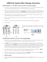
How To Replace Stages 1, 2, 3 Pre-Filters:
1. Turn OFF cold water supply to RO system. Turn OFF tank’s ball-valve. Lift up RO faucet lever
briefly to relief the built-up pressure inside the RO system. This will make opening the hous-
ings easier.
2. Open housing: Have the RO standing upright. Slip the plastic wrench onto the #1 housing.
Looking down from a top view, you should open the housing turning clockwise. If necessary,
lay the RO down on the floor to get a better leverage. If the housing is too tight, use a ham-
mer and tap on the wrench handle to help turn the wrench.
3. Discard 3 used filters, wash housings with mild soap, rinse off. Put 3 new filters into their re-
spective housing: sediment filter in stage-1, carbon block filter in stages 2 & 3.
4. Close up the housing. Make sure each housing has a black O-ring in the thread groves.
Use wrench to tighten each housing.
5. Remember: Turn ON the cold water supply and OPEN the tank valve after you fin-
ished changing filters!
6. Check for leaks!
Use
Wr
ench
3rd
Stage
2rd
Stage
1rd
Stage
After taking the housing off, take out the
dirty filters and put the new 3 pre=filters
in. Remember, Stage 2 and Stage 3 are
the same carbon filters.
STEP 1 STEP 2

16
How to Replace Stage-4 Membrane:
There are several membranes (2 to 4 depending on model) provided with your system. Please
insert the membrane into each housing one-by-one to prevent mis-connecting the tubing.
1. Locate the Membrane housings on the system. See Fig 8
2. The number of housing matches with the number of membranes provided. Each housing is
labeled as: “MEM-1”, “MEM-2”, “MEM-3”, “MEM-4” depending on your Ro model.
3. Start with “MEM-1” housing: Insert the membrane into one housing at a time. Finish up the
connection before going onto the next housing. This will prevent confusing the tubing order.
Insert membrane: See Fig.8A Remove the tubing from the membrane housing cap. Open the
cap. Insert membrane all the way into the housing tightly with the correct side going in first as
shown below. The end with 2 black-rings goes in first.
4. Close the housing cap. Re-connect the tubing to cap as before. Make sure to connect each
color coded tubing to its corresponding (matching) housing. This is important for proper filtra-
tion.
5. Proceed to insert the other membranes in the same manner.
Note: Make sure the membrane’s end with 2 black-rings goes into housing first!
Fig. 8A
1. Push in and hold down on the collet ring
square against the tting. With the collet
held in this position the tube can be removed.
2. Unscrew membrane housing
cap (counter clockwise)
b
an
e
ho
us
in
g
Post Carbon Filter
Fig. 8
/