Page is loading ...

– 6 –
– 7 –
L
Assembly information sheet for Multifeed - SAT - Set
L
Important information:
As special tools are required to install a satellite system and some legal regulations apply, we recommend
that you have a specialised company install the system.
Are you technically skilled? Do you have the appropriate tools? If so, the information sheet can be used as a
guide to assembling/installing the Multifeed SAT Set. The most important points to note are presented briefly
in clear steps.
Please read all instructions carefully before you start installation.
Step 1:
Choosing a suitable location
A satellite dish needs an absolutely free sight connection to the satellite. There should be no branches,
trees, fences and definitely no walls obstructing the connection. The exact direction is set later by trial and
fine adjustment, but the primary consideration is an unobstructed view in the corresponding direction and
approx. x° tilt (see the information provided by the satellite provider or your dealer for corresponding details
on satellite positioning).
Obstructions to reception such as high trees, buildings etc. are the
most common cause of problems. This set is designed for mounting
on building walls, which also facilitates the installation of the two
single LNBs. Optimally, the satellite receiver mirror should be moun-
ted min. 2 metres below a protruding roof (if installed more than min.
2 metres from the roof, the antenna does not have to be earthed). If
this is not the case, please earth the dish in accordance with EN-
50083-1. The roof may not obstruct the passage of rays between the
dish and the satellite, as otherwise the reception is compromised. If
the sight connection to the satellite is ok, it makes no difference
whether the dish is at ground level or 10 metres above ground.
If various mounting locations are available, you can decide according to the following criteria: Where is the
cable length to the receiver shortest? Where is the dish well protected from mechanical damage? Where is
it least conspicuous?
Step 2:
Attaching the wall mount
For the wall mount (Hama item number 47487, fig. 1.0), you must use 5 size 8
anchors and corresponding hex screws. The wall mount must be “rock solid”, as
even minimal movements can cause reception problems.
Step 3:
Assembling the satellite receiving mirror
Please assemble the satellite receiving mirror as shown in the
enclosed drawing.
The two universal single LNBs (Hama item number 29125) are
secured via the enclosed mounting brackets and the multifeed
bracket on the feed arm of the mirror.
Step 4:
Mounting the dish provisionally
The following tools are required:
Fork wrench (2x wrench size 13 & 2x wrench size 10), Phillips-head screwdriver, flat-head screwdriver,
angle meter, compass and ideally a SAT finder
Set the vertical alignment (elevation) via the angle meter
(see fig. 1.2 & 1.3) and tighten the adjusting screw slightly
(do not tighten fully!).
Place the dish on the wall mount and tighten the screws
leaving enough play so that the dish can be rotated for hori-
zontal adjustment (azimuth) (fig. 1.4).
First, point the dish precisely in the correspon-
ding direction and from there in line with the
positioning of the receiving satellite. Now you
have a good starting position for precise adjust-
ment.
Fig. 1.3
Fig. 1.2
Fig. 1.4
Fig. 1.0

– 9 –
L
– 8 –
L
from the front and the contact between the shielding and the metal of the plug is optimal.
Please Note: Tangled shielding wires inside the connector can cause short circuits!
2. Connect the two LNBs and the DISEqC switch with two separate coaxial cables. Please use the enclosed
rubber bushings to protect the connectors for external mounting. Lay another connection cable to the
receiver.
TIP: If you are using a digital receiver, the signal strength is shown in the menu of the receiver when you
connect the coaxial cable.
When you have successfully fine-adjusted the dish, you can complete the assembly process.
We recommend that you attach the antenna cables to the feed arm using weatherproof adhesive table or
cable ties to secure the coaxial cable for external mounting. Turn the cable generously around the
parabola antenna or make a little loop.
This prevents cable damage.
TIP: If there is no cable shaft, u-shaped nails are an inexpensive solution for attaching the coaxial cable
to the wall.
TIP: AZIMUTH (horizontal swivel), ELEVATION (vertical swivel)
When you have made the optimal horizontal adjustment using a compass, azimuth/elevation table and a
SAT level meter, loosen the screw(s) for vertical adjustment. Tilt the dish upwards until the receiver
indicates a clear signal. If the receiver still does not have an optimal signal, you must repeat the horizon
tal/vertical adjustment until a corresponding signal is indicated. To complete the configuration, all
fastening screws must be tightened, so the dish cannot be moved by mechanical influences.
Check your receiver to see whether the TV reception for a station is ok. We recommend doing this for the
channel in the pre-programmed station list with the strongest signal. Use the signal strength menu for digital
satellite receivers as a countertest. Remember that this display is slow to react, so allow some time for it to
change.
You can then exit the signal strength menu and browse through the stations to test the signal. If all settings
are correct, the reception of all TV stations should be perfect. When you are happy with the reception, you
can finally tighten all screws of the satellite receiving mirror fully.
Still no picture?
Possible causes:
- Is the receiver power supply switched on and the connection between the LNBs, DISEqC and receiver
ok?
- Is the receiver sending/programming the wrong DISEqC command?
- Is the cable between the LNBs and the receiver ok (no short circuit in the F connector)?
- Is the rough direction correct (if necessary, measure with a compass)?
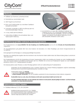
LNB
DISEqC
Wall
mount
Parabolic-
mirror
Step 5:
Fine adjustmentent
The receiver has been connected to the two universal single LNBs (fig. 1.5). A
compass, an azimuth / elevation table and a SAT level meter can be used for further fine adjustment.
In order to guarantee clear reception even when the weather is bad, fine adjustments must be made to the
dish before it is finally secured. Optimal reception, even in poor weather conditions, can only be guaranteed
when the dish is aligned properly.
Step 6:
Further installation/adjustment of the satellite system
1. Assembling the F connectors:
Attach the enclosed F connector to the end of the coaxial cable (Hama item number 29799) as shown in
figure 1.6.
Strip approx. 1.5cm of the external insulation and bend the shielding wires back. Shorten the shielding wires
somewhat, so that they do not protrude from the connector. Strip a further 0.6 com from the inner part. Take
the connector and thread it with the rear threads onto the stripped cable, so that the inner core protrudes
Fig 1.5
Wire mesh
screwable
F-connector
Silver foil
/