Hinkley 22 Inch ELI Indoor LED Ceiling Fan User manual

Category
Household fans
Type
User manual
CEILING FAN INSTRUCTION MANUAL
22" ELI
INDOOR LED FAN
LED
SO WE’RE HERE IF YOU HAVE A QUESTION, NEED SOME
HELP OR WANT TO CHAT ABOUT OUR PRODUCTS. SEND
SUGGESTIONS OUR WAY TOO—WE’RE ALWAYS LOOKING TO
MAKE YOUR EXPERIENCE WITH HINKLEY A POSITIVE ONE.
This manual contains complete instructions for the
installation and operation of this fan. It has been
designed to make the installation process as easy as
possible. If you are unfamiliar or uncomfortable with
wiring, please contact a qualified electrician. If you
need additional assistance or have any questions,
please reach out to us.
For warranty information, visit hinkley.com.
>SERVICE@HINKLEY.COM
>800.HINKLEY
>LETS SEE THAT HINKLEY STYLE @HINKLEY
#HINKLEYSTYLE
WE WANT YOU TO LOVE YOUR NEW FAN
©2021 Hinkley Lighting, Inc. | hinkley.com | 01
WARNING:
Read and follow these instructions carefully and be mindful of all warnings shown throughout.
TABLE OF CONTENTS
02
03
03
04
05
05
06
08
09
10
12
14
14
15
15
16
INSTALLING THE WALL CONTROL
OPERATING
CARE AND CLEANING
TROUBLESHOOTING
ENERGY GUIDE
SPECIFICATIONS
SMART BY BOND
GENERAL INSTALLATION & OPERATING
INSTRUCTIONS
IMPORTANT SAFETY PRECAUTIONS
TOOLS & MATERIALS REQUIRED
UNPACKING YOUR FAN
PREPARATION
INSTALLING THE HANGING BRACKET
HANGING THE FAN
ELECTRICAL CONNECTIONS
INSTALLING THE BLADES
02 | hinkley.com
GENERAL INSTALLATION & OPERATION INSTRUCTIONS
1
2
3
4
5
6
7
8
9
10
To ensure the success of the installation, be sure to read the instructions and review the diagrams thoroughly before beginning.
To avoid possible electric shock, be sure electricity is turned off at the main power box before wiring. All electrical connections
must be made in accordance with local codes, ordinances and/or the National Electric Code. If you are unfamiliar with the
methods of installing electrical wiring and products, secure the services of a qualified and licensed electrician as well as
someone who can check the strength of the supportive ceiling members and make the proper installation(s) and connections.
WARNING: To reduce the risk of fire, electric shock, or other personal injury, mount fan only on an outlet box or supporting system
marked acceptable for fan support of 35 lbs (15.9 kg) or less and use mounting screws provided with the outlet box. Most outlet
boxes commonly used for the support of lighting fixtures are not acceptable for fan support and may need to be replaced.
Consult a qualified electrician if in doubt.
Make sure that your installation site will not allow rotating fan blades to come in contact with any object. Blades should be a t least
7 feet from floor.
Blades should be attached after motor housing is hung and in place. Fan motor housing should be kept in the carton until ready
to be installed to protect its finish. If you are installing more than one ceiling fan, make sure that you do not mix fan blade sets, as
each blade is part of a weighted set.
After making electrical connections, spliced conductors should be turned upward and pushed carefully up into outlet box. The
wires should be spread apart with the common conductor and the grounding conductor on one side of the outlet box, and the
"HOT" wires on the other side.
Electrical diagrams are for reference only.
After fan is completely installed, check to make sure that all connections are secure to prevent fan from falling and/or causing
damage or injury.
The fan can be made to work immediately after installation - the bearings are adequately charged with grease so that, under
normal conditions, further lubrication is not necessary for the life of the fan.
Do not operate the reverse switch while the fan blades are in motion. The fan must be turned off and the blades stopped before
reversing the blades direction.
IMPORTANT SAFETY PRECAUTIONS
TOOLS & MATERIALS REQUIRED
WARNINGS:
PHILLIPS SCREWDRIVER
• FLAT SCREWDRIVER
WRENCH OR PLIERS
WIRE CUTTER
• STEPLADDER
WIRING SUPPLIES AS REQUIRED BY
ELECTRICAL CODE
©2021 Hinkley Lighting, Inc. | hinkley.com | 03
• Disconnect power by removing fuse or turning off circuit breaker before installing the fan and/or optional lighting.
• Support directly from building structure.
• To reduce the risk of fire, electric shock or personal injury, mount to outlet box marked "acceptable for fan support" and use mounting
screws provided with the outlet box. Most outlet boxes commonly used for the support of lighting fixtures are not acceptable for fan
support and may need to be replaced. Consult a qualified electrician if in doubt.
• Do not use an incandescent light dimmer. Do not use this fan with any transformer type fan speed control device.
• To reduce the risk of personal injury, do not bend the blade arms when installing them, balancing the blades or cleaning the fan.
Do not insert any object(s) between rotating fan blades.
NOTE:
The important precautions, safeguards and instructions appearing in this manual are not meant to cover all possible conditions
and situations that may occur. It must be understood that common sense, caution and carefulness are factors which cannot be
built into this product. These factors must be supplied by the person(s) installing, caring for and operating the unit.
©2021 Hinkley Lighting, Inc. | hinkley.com | 04
UNPACK YOUR FAN AND CHECK THE CONTENTS.
• Do not discard the carton. If warranty replacement or repair is ever necessary, the fan should be returned in original packing. Remove
all parts and hardware. Do not lay motor housing on its side, or the decorative housing may shift, be bent or damaged.
Examine all parts. You should have the following:
UNPACKING YOUR FAN
XX=FAN FINISH
1
2
3
4
5
6
7
8
PACKAGE CONTENT
Hanging Bracket
Ceiling Canopy
Downrod Asm.
Yoke Cover
Fan blade (12")
Receiver Incl. 5 Wire Nuts )
HIRO Wall Control w/2032 Battery,
Cradle A, Wall Plate, Face Plate,
remote control,
2 countersunk head tapping screws
2 mechanical screws and 2 Wire Nuts
Cradle B Wall Plate
,,
switch
(for flat wall use only)
12 Hardware Bag
x
Fan Housing with Motor
Trim Ring
Fan nut cover With clip
9(4)LED Bulbs
10
11
T8, E12, 4.5W)
Safety cable hardware
(wood screw, flat washer, cable clamp)
980014FWH/
CN905022
MH905022FHB
CN905022
EST8-4.5W-27
BL905022Fxx
YC902352Fxx
DR94016Fxx
CA900752Fxx
HINKLEY
NOTE: Design of parts shown above may look slightly different for
your specific model of fan.
1
2
3
4
5
6
12
TO MOTOR N
TO MOTOR L
FOR LIGHT
AC IN L
AC IN N
10
UP
HINKLEY
CR2032
11
UP
KCD1 6A 250V AC
25T85 1E4 PTI 175V
CQC CE UL
7
8
9
Bracket Mounting Hardware
(wood screws, screws, lock washers,
star washers, flat washers, wire nuts),
PREPARATION
Parts identification on assembled fan.
©2021 Hinkley Lighting, Inc. | hinkley.com | 05
Blade
Canopy
Motor Housing
INSTALLING THE HANGING BRACKET
Ceiling Fan
Outlet Box
Hanger
Bracket
Outlet Box
Screw
Flat Washer
Lock Washer
CAUTION: To avoid possible electrical shock, be sure electricity is turned off at
the main power box before wiring. All wiring must be in accordance with
National and Local Electrical Codes and the ceiling fan must be grounded as
a precaution against possible electric shock.
Fig. 1
1
2
3
4
Locate ceiling joist where fan is to be mounted, being sure location
agrees with the requirements in the minimum clearance section of this
guide. Wood joists must be sound and of adequate size to support 35
pounds (See page 2, items 3 and 4).
If not already present, mount a UL listed outlet box marked "suitable for
fan support" following the instructions provided with the outlet box. The
outlet box must be able to support a minimum of 35 pounds.
Remove canopy from hanger bracket. Remove twist-lock trim ring by
rotaing counter-clockwise. Remove canopy screw that does not have
key slot in canopy. Loosen screw with key slot and remove canopy.
Attach hanging bracket to outlet box using screws provided with the
outlet box.
PREPARATION:
Verify you have all parts before beginning the
installation. Check foam insert closely for missing
parts. Remove motor from packing. To avoid
damage to finish, assemble motor on soft padded
surface or use the original foam inset in motor box.
DO NOT LAY MOTOR HOUSING ON ITS SIDE
AS THIS COULD RESULT IN DAMAGE OF THE
DECORATIVE ENCLOSURE.
©2021 Hinkley Lighting, Inc. | hinkley.com | 06
HANGING THE FAN
Fig. 1
Downrod
Cross Pin
Hanger
Ball Set Screw
Downrod
Hook-up
(3) Wires
Downrod Pin
Security Set Screws
Mounting Collar
Cotter Pin
Top of Fan Body
1
2
3
4
5
Remove ball from downrod by loosening set screw in the
side of the ball. Slide ball down and remove ball pin;
remove ball. (Fig. 1)
Carefully support fan body (motor) in its styrofoam packing
with the mounting collar (where the wires come out) facing
upward.
Loosen the two security set screws and remove the
downrod pin and cotter pin from the coupling on top of the
motor assembly. (Fig. 2)
Carefully feed the electrical lead wires and safety cable
from the fan through the downrod. Thread downrod into
coupler until holes align. Insert downrod pin through holes
in mounting collar and downrod; clip cotter pin through
small hole in end of downrod pin to hold downrod in place.
Tighten security set screws against downrod using a large
flat blade screwdriver to ensure a tight fit against downrod.
Tighten nuts against mounting collar.
Safety Cable
HANGING THE FAN
07 | hinkley.com
Fig. 4
INSTALLATION OF SAFETY CABLE SUPPORT
Attach the wood screw and the flat washer to the ceiling joist as
shown (do not fully tighten). Slide the cable clamp onto the
safety cable from the fan. Loop the safety cable around the
wood screw that was just attached to ceiling joist. Feed the end
of the cable into the clamp and pull as much cable through as
possible. Firmly tighten screw in the clamp. Cut off excess cable.
Safety Cable
Wood Ceiling Joist
Safety Cable Clamp
Safety Cable Loop
Wood Screw
And Washer
HANGING THE FAN
Ground Wire
Top of Fan Body
Hanger ball
Hook-up (3) Wires
Yoke Cover
Downrod
Canopy
Set screw
Cross Pin
REMEMBER to turn off the power before you begin.
To properly install your ceiling fan, follow the steps below.
Slip the yoke cover, trim ring and canopy onto the downrod. (Fig. 3)
Slide the hanger ball onto the downrod, insert the cross pin through
Lift ball/downrod/fan into hanger bracket opening.
NOTE: The tab opposite hanger bracket opening should fit in slot
on ball. (Fig. 4)
6
7
8
NOTE:
6 feet of lead wire is supplied on the fan for use with
longer downrods.
Trim Ring
©2021 Hinkley Lighting, Inc. | hinkley.com 08
ELECTRICAL CONNECTIONS
1
2
Motor to Receiver Electrical Connections:
Connect the black wire from the fan to the black wire
marked "TO MOTOR L" on the receiver. Connect the
white wire from the fan to the white wire marked "TO
MOTOR N" on the receiver. Connect the blue wire from
the fan to the blue wire marked "FOR LIGHT" on the
receiver. Secure all the wire connections with the plastic
wire nuts provided.
Receiver to House Supply Wires Electrical Connections:
Connect the black (hot) wire from the ceiling to the black
wire marked "AC in L" from the receiver. Connect the
white(neutral) wire from the ceiling to the white wire
marked "AC in N" from the Receiver. Secure the wire
connections with the plastic wire nuts provided.
REMEMBER -Turn off the power! NOTE - Control must be installed
within 30 feet of fan.
CAUTION: To reduce the risk of electric shock, this fan must be
installed with an isolating wall control/switch.
White (neutral)
Green or bare
copper (ground)
White ("AC IN N")
Outlet box
Black (hot)
Black ("AC IN L")
Receiver
White (neutral)
White ("to motor N")
Ground
(green)
(Connect to
ground wire on
hanger bracket
if no house
ground wire
exists.)
Black ("to motor L")
Blue (for light)
Blue (for light)
Black (motor)
WARNINGS: Check to see that all connections are tight,
including ground, and that no bare wire is visible at the wire
nuts, except for the ground wire.
©2021 Hinkley Lighting, Inc. | hinkley.com | 09
INSTALLING THE BLADES
Press blade (2) onto motor shaft making sure pin in shaft seats in
slot in top of blade
Attach clip (3) through hole in motor shaft (4)
Thread decorative cap (1) onto end of motor shaft (Left Hand
Thread)
1
2
3
1
4
3
2
1
©2021 Hinkley Lighting, Inc. | hinkley.com | 10
INSTALLING THE WALL CONTROL
Fig. 1
REMEMBER to turn off the power before you begin.
NOTE - Secures to any surface or application: flat wall, single gang
box, multi gang box.
1
2
3
4
Option 1. Flat Surface Installation
Select a desired location. Use the wall plate to mark the
location of the mounting holes. Plastic wall anchors or
mounting screws are needed for this application. (Fig. 1)
Seat the cradle B into the wall plate. Secure the wall plate
to the wall using the provided hardware.
Snap the face plate cover onto the wall bracket.
Remote transmitter will be held in place with built in magnets.
Remove the existing wall plate and the old switch from the
wall outlet box.
Seat the cradle A into the wall plate. (Fig. 2)
Connect the black lead wires from the switch in the cradle A
to the black wires in the switch box. Hot input wire to one of
the cradle A switch leads. Power lead to the fan is connected
to the remaining switch lead.
Connect the wall plate / cradle A assembly to the wall outlet
box using the supplied hardware.
Snap the face plate cover onto the wall bracket.
Remote transmitter will be held in place with built in magnets.
1
2
3
4
5
6
Option 2. For single gang box
Transmitter
Face plate
Wall plate Cradle B
Wall
Plastic
anchor
Fig. 2
Outlet box
Transmitter
Face plate
Wall plate
Cradle A
HIRO Control System
11 | hinkley.com
Fig. 3
Remove the existing wall plate and old switch from the wall outlet box. (Fig. 3)
Connect the black lead wires from the switch in the cradle A to the black wires in the switch box. Hot input wire to one of the cradle
switch leads. Power lead to the fan is connected to the remaining switch lead. (Fig. 4)
Attach the cradle A to the wall switch box using the supplied hardware.
Attach the multi-gang faceplate to the switch set in the wall outlet box. Cradle A of Hinkley switch will fit in any standard decora
face plate.
Remote transmitter will be held in place with built in magnets.
1
2
3
4
5
Option 3. Multi Gang Wall Switch Box Installation
Outlet box
Face plate
Switch
Fig. 4
Outlet box
Transmitter
Face plate
Cradle A
HIRO Control System
©2021 Hinkley Lighting, Inc. | hinkley.com | 12
OPERATION
This ceiling fan is equipped with an
automatically learned type remote control.
There is no frequency switches on the
receiver or transmitter. The fan can start to
use once the pairing process is done.
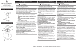
Remove the panel from the transmitter and
then install one 2032 battery (included). You
need to use a coin to open or close the battery
cover. To prevent damage to transmitter,
remove the battery if not use for long periods
of time (Fig. 1)
Fig. 1
Fig. 2
Signal light
ON
OFF
Pairing Process
NOTE: If installing/pairing more than
one fan in an area, the power must be
disconnected from all fans except the
one fan being paired.
With the fan’s power off, restore power to
the fan. Press and hold “ ” button for about
5 seconds and release. If optional light kit is
installed, the light kit will flash three times
and the motor spin up for 10 seconds on low
speed. The fan has completed the pairing
process with the wall control and is ready
for use.
NOTE: A single fan can be controlled with as
many as 3 wall controls in one room. Every
control will need to repeat the pairing
process based on instructions above and
all controls must be within 30 feet of the fan.
1
2
3
4
5
button:
Press this button and release instantly
to turn on or off the light.
button:
Press and hold to dim or brighten
lights to the desired level and release
button:
Press button for turn on and setting
1-3 fan speed.
button:
Press this button to turn the fan off.
Signal light (Fig. 2)
WARNING: Chemical Burn Hazard.
Keep batteries away from children.
This product contains a lithium button/coin
cell battery. If a new or used lithium button
/coin cell battery is swallowed or enters the
body, it can cause severe internal burns
and can lead to death in as little as 2 hours.
Always completely secure the battery
compartment. If the battery compartment
does not close securely, stop using the
product, remove the batteries, and keep it
away from children. IF you think batteries
might have been swallowed or placed inside
any part of the body, seek immediate medical
attention.
The batteries shall be disposed of properly,
including keeping them away from children;
Even used cells may cause injury.
HIRO Control System
13 | hinkley.com
Fig. 3
Fig. 4
SUMMER MODE
CLOCKWISE DIRECTION)
WINTER MODE
COUNTERCLOCKWISE
DIRECTION)
7
8
Summer Mode and Winter Mode Operation
Summer Mode :
A DOWNWARD airflow creates a cooling effect as shown in Figure 3. This allows you to set your air conditioner on a warmer setting
without affecting your comfort.
Winter Mode:
An UPWARD airflow moves warmer air off the ceiling area as shown in Figure 4. This allows you to set your heating unit on a cooler
setting without affecting your comfort.
Reversing switch to change blade direction is located on the top of motor housing.
©2021 Hinkley Lighting, Inc. | hinkley.com | 14
CARE AND CLEANING
TROUBLESHOOTING
CAUTION:
Switch off power supply before carrying out any of these checks.
PROBLEM SOLUTION
Periodically it may be necessary to re-tighten screws to prevent clicking or humming sound during operation. This is especially true in climates
with broad temperature and humidity ranges.
When dusting the blades, you must support the blade to prevent bending - no pressure should be applied to the blades. If you experience any
flaws in the operation of your fan, please check the following points.
FAN WILL
NOT START
FAN SOUNDS
NOISY
1. Check main and branch circuit breakers and/or fuses.
2. Check line wire connections to fan housing wiring. Make sure forward/reverse switch is set to one or the other
position, not stuck in between.
1. Check and make sure that all screws in motor housing are snug (but not over tight).
2. Check that wire connectors in canopy are not rattling against each other
3. Check that all bulb(s) are well held in the sockets.
4. Check that the canopy is firmly attached to hanging bracket and not vibrating against ceiling.
5. Check to assure set screws on both ends of downrod are tight (motor couple and hanger
ball)
15 | hinkley.com
ftc.gov/energy
• The higher the airflow, the
more air the fan will move
• Airflow Efficiency: 34 Cubic
Feet Per Minute Per Watt
Airflow
3,700
Cubic Feet Per Minute
Based on 12 cents per kWh and 6.4 hours use per day
• Your cost depends on rates
Energy Use: 21 Watts
and use
$3$34
Cost Range of Similar Models (19” – 84”)
Estimated
Yearly Energy Cost
$6
All estimates based on typical use, excluding lights
ENERGY GUIDE SPECIFICATIONS
AVERAGE PERFORMANCE AND ENERGY INFORMATION
PERFORMANCE
SPECIFICATIONS
STANDARD
HIGH SPEED LOW SPEED
Airflow (CFM)
Energy Use (Watts)
Airflow Efficiency (CFM/W)
Energy Costs (Yearly)
Amps
RPMs
Airflow Shown Is a Weighted Average of High and Low Cubic Feet per Minute Based on Close to Ceiling
832
25.7
23
$7
0.21
1191
551
14.7
37
$4
0.18
751
©2019 Hinkley Lighting, Inc. | hinkley.com | 16
SMART BY BOND (SOLD SEPARATELY)
How to correct "Fan paired to wrong transmitter" on Smart by
Bond fans supporting multiple transmitters:
a) Open the Bond Home app.
b) Tap on the Fan you want to modify.
c) Tap the settings icon in the upper right corner.
d) Scroll down and tap "Manage Remotes".
e) Delete just the remotes in question; or, use the triple-dot menu
and select "Forget all remotes".
f) Tap "Learn a new remote".
g) Follow on-screen prompts to (re) learn the desired remotes into
the fan.
a) Turn mains power OFF to all fans.
b) Turn mains power ON only for the fan needing code correction.
c) Within 15 seconds of turning on, hold down the Speed 1 button
on any compatible transmitter for 20 seconds.
d) The fan light should blink 5 times and may spin up on low speed
for 10 seconds.
e) Wait 10 seconds.
f) Hold down the Power button on the transmitter you wish to pair.
The fan light should flash three times and the motor spin up for
10 seconds on low speed.
g) If you were using the fan on Wi-Fi, you will need to reconnect to
Wi-Fi.
Smart Phone Method (recommended)
Factory Reset Method
a) Turn mains power OFF to the fan.
b) Turn mains power back ON on the fan.
c) Hold down the Power button on the transmitter for 5 seconds,
until the fan light flashes 3 times.
d) Repeat steps a--c above 4 more times.
e) The fan's memory is now totally overwritten, and it has forgotten
all other remotes.
Brute Force Method
https://bondhome.io/app
HINKLEY SMART FAN OPTIONS:
In addition to the included wall control, you can control your Hinkley
fan through the Bond app.
To use the app, download it for free from the App Store or Google
Play.
Open the app to create your account. You can also login with
your Facebook or Google account.
Next, set up a WiFi connection. You will need the SSID and WiFi
password for the network you want to connect to.
You will receive a prompt to choose the finish of your fan and
name your fan device.
The app will walk you through the main screen and show you
how to change fan speeds, dim the light, set timers or utilize
breeze mode.
NOTE: Maximum of 2 fans can operate on a circuit through the
wall control. Maximum of 12 fans can operate on a circuit through
an on/o switch or breaker when utilizing the app for the fan
control (without the wall control in the circuit).
HINKLEY IS PROUD TO PROVIDE YOU WITH CEILING FAN
PRODUCTS THAT ENHANCE YOUR SPACE WITH COMFORT,
PURPOSE AND STYLE. AS A FAMILY COMPANY, WE ARE
COMMITTED TO DESIGN, PERFORMANCE AND QUALITY,
AND WHAT’S IMPORTANT TO YOU IS PARAMOUNT TO US.
FOR A COMPLETE ASSORTMENT OF OUR PRODUCTS AND
SOURCE BOOKS, VISIT HINKLEY.COM.
GLOBAL HEADQUARTERS
33000 Pin Oak Parkway | Avon Lake, Ohio 44012
T (440) 653 5500 | F (440) 653 5555 | hinkley.com
  • Page 1 1
  • Page 2 2
  • Page 3 3
  • Page 4 4
  • Page 5 5
  • Page 6 6
  • Page 7 7
  • Page 8 8
  • Page 9 9
  • Page 10 10
  • Page 11 11
  • Page 12 12
  • Page 13 13
  • Page 14 14
  • Page 15 15
  • Page 16 16
  • Page 17 17
  • Page 18 18
  • Page 19 19
  • Page 20 20
  • Page 21 21
  • Page 22 22
  • Page 23 23
  • Page 24 24
  • Page 25 25
  • Page 26 26
  • Page 27 27
  • Page 28 28
  • Page 29 29
  • Page 30 30
  • Page 31 31
  • Page 32 32
  • Page 33 33
  • Page 34 34
  • Page 35 35
  • Page 36 36
  • Page 37 37
  • Page 38 38
  • Page 39 39
  • Page 40 40
  • Page 41 41
  • Page 42 42
  • Page 43 43
  • Page 44 44
  • Page 45 45
  • Page 46 46
  • Page 47 47
  • Page 48 48
  • Page 49 49
  • Page 50 50
  • Page 51 51
  • Page 52 52
  • Page 53 53
  • Page 54 54
  • Page 55 55
  • Page 56 56
  • Page 57 57
  • Page 58 58
  • Page 59 59
  • Page 60 60

Hinkley 22 Inch ELI Indoor LED Ceiling Fan User manual

Category
Household fans
Type
User manual

Ask a question and I''ll find the answer in the document

Finding information in a document is now easier with AI