Toshiba 4400 series User manual
- Type
- User manual

Part # 64527-010
November 2021
Manufactured in the USA
© Copyright 2021 TOSHIBA International Corporation
All rights reserved.
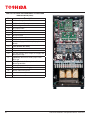
4400 SERIES
INSTALLATION AND OPERATION MANUAL
THREE PHASE - 15/20/25/30/50/80/100 KVA


4400 Series Installation and Operation Manual – 64527-010
Product Use and Warranty Restrictions
The Toshiba products listed in this document are intended for usage in general electronics applications (computer, personal
equipment, oce equipment, measuring equipment, industrial robotics, domestic appliances, etc.). These Toshiba products
are neither intended nor warranted for usage in certain applications outlined in Section 2.4 Unintended Usage.
NOTICE
PLEASE INFORM TOSHIBA INTERNATIONAL CORPORATION OR AUTHORIZED REPRESENTATIVE IN
CASE OF INCONSISTENCIES, OMISSIONS, OR QUESTIONS.
Contact us at: [email protected] or visit us at:
www.toshiba.com/tic/industrial/uninterruptible-power-systems
The instructions contained in this manual are not intended to cover all of the details or variations in equipment, or to provide
for every possible contingency concerning installation, operation, or maintenance. Should further information be required
or if problems arise which are not covered suciently, contact your Toshiba sales oce or call Toshiba Power Electronics
Division at 855-803-7087
Nothing in this manual shall alter Toshiba International Corporation’s standard terms and conditions or the
conditions of any written sales contract.
Any electrical or mechanical modications to the equipment discussed herein, without prior written consent of Toshiba
International Corporation, will void all warranties and may void the UL/CUL/CE/ETL listing. Unauthorized modications can
also result in personal injury, loss of life, or destruction of the equipment.
QUALIFIED PERSONNEL ONLY
Only qualied persons are to install, operate, or service this equipment according to all applicable codes and
established safety practices. The denition of Qualied Personnel is detailed in Section 2.3

4400 Series Installation and Operation Manual – 64527-010
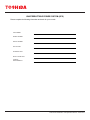
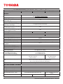
UNINTERRUPTIBLE POWER SYSTEM (UPS)
Please complete the following information and retain for your records.
JOB NUMBER
MODEL NUMBER
SERIAL NUMBER
APPLICATION
SHIPMENT DATE
INSTALLATION DATE
STARTUP
PERFORMED BY

4400 Series Installation and Operation Manual – 64527-010
Purpose
This manual provides information on how to safely install your Toshiba International Corporation power electronics product.
This manual includes a section of general safety instructions that describes the warning labels and symbols that are
used throughout the manual. Read the manual completely before installing, operating, or performing maintenance on this
equipment.
This manual and the accompanying drawings should be considered a permanent part of the equipment and should be
readily available for reference and review. Dimensions shown in the manual are in metric and/or the English customary
equivalent.
Toshiba International Corporation reserves the right, without prior notice, to update information, make product changes,
or discontinue any product or service identied in this publication. (See https://www.toshiba.com/tic/industrial/uninterruptible-power-
systems. )
Toshiba is a registered trademark of the Toshiba Corporation. All other product or trade references appearing in this manual
are registered trademarks of their respective owners.
Toshiba International Corporation shall not be liable for direct, indirect, special, or consequential damages resulting from the
use of the information contained within this manual.
This manual is copyrighted. No part of this manual may be photocopied or reproduced in any form without the prior written
consent of Toshiba International Corporation.
© Copyright 2021 Toshiba International Corporation
All rights reserved.
Printed in the U.S.A.
Toshiba Customer Support Center
Contact the Toshiba Customer Support Center for assistance with application information or for any problems that you may
experience with your Toshiba Uninterruptible Power System (UPS).
Toshiba Customer Support Center
8 a.m. to 5 p.m. (CST) – Monday through Friday
USA Toll Free (855) 803-7087
Tel (877) 867-8773 Fax (713) 896-5212
E-mail – [email protected]
Web – https://www.toshibaups.com
You may also contact Toshiba by writing to:
TOSHIBA INTERNATIONAL CORPORATION
SOCIAL INFRASTRUCTURE SYSTEMS GROUP
POWER ELECTRONICS DIVISION - UPS
13131 West Little York Road
Houston, Texas 77041-9990
Attn.: 4400 UPS Product Manager
For further information on Toshiba products and services, please visit our website at:
www.toshiba.com/tic/industrial/uninterruptible-power-systems

This page left intentionally blank

i
4400 Series Installation and Operation Manual – 64527-010
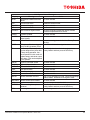
Contents
1 Introduction ................................................................................................................................... 1
2 General Safety Instructions ......................................................................................................... 2
2.1 Symbols ...........................................................................................................................................................2
2.2 Signal Words ...................................................................................................................................................3
2.3 Qualied Personnel .........................................................................................................................................3
2.4 Factory Authorized Personnel .........................................................................................................................3
3 Important Safety Instructions ...................................................................................................... 4
3.1 Unintended Usage ...........................................................................................................................................5
3.2 Disclaimer ........................................................................................................................................................5
3.3 General Maintenance ......................................................................................................................................6
3.4 Transporting .....................................................................................................................................................7
4 Unpacking ..................................................................................................................................... 8
4.1 General Instructions ........................................................................................................................................8
4.2 Unpack the 15-30kVA Model UPS (with Casters) ............................................................................................8
4.3 Unpack the 50kVA Model UPS (with Casters) ...............................................................................................10
4.4 Unpack the 80-100kVA Model UPS ............................................................................................................... 11
4.5 Inspection/Storage .........................................................................................................................................12
5 Warning Labels ........................................................................................................................... 13
6 Storage/Operating Environment ............................................................................................... 19
6.1 Storage Environment ....................................................................................................................................19
6.2 Precautions ....................................................................................................................................................19
6.3 Maintenance Precautions ..............................................................................................................................21
6.4 UPS Component Information .........................................................................................................................22
7 Installation Safety ....................................................................................................................... 23
8 Installation................................................................................................................................... 26
8.1 Unpacking ......................................................................................................................................................26
8.2 UPS Clearance ..............................................................................................................................................26
8.3 UPS Anchorage .............................................................................................................................................28
8.4 15-50kVA Anchorage - Standard ...................................................................................................................29
8.5 80-100kVA Anchorage - Standard .................................................................................................................30
8.6 Power Cable Access ......................................................................................................................................31
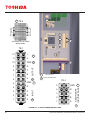
8.7 UPS Parts Identication – 15–30kVA ............................................................................................................33
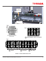
8.8 UPS Parts Identication – 50kVA ..................................................................................................................35
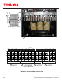
8.9 UPS Parts Identication – 80-100kVA ...........................................................................................................37
9 UPS Wiring .................................................................................................................................. 39
9.1 Wiring Safety .................................................................................................................................................39
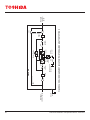
9.2 One-Line Diagram .........................................................................................................................................40
9.3 Parallel Battery Cable Installation Instructions ..............................................................................................44
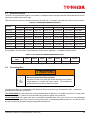
9.4 Power Terminal Blocks and Cable Sizing ......................................................................................................48
9.5 External Breakers ..........................................................................................................................................53
9.6 Grounding Wire .............................................................................................................................................53
9.7 Control Wiring ................................................................................................................................................54
10 Communication Interfaces ...................................................................................................... 55
10.1 Remote Contacts .........................................................................................................................................55
10.2 UPS LAN Shutdown Signal Operation .......................................................................................................55

ii 4400 Series Installation and Operation Manual – 64527-010
10.3 RS-232C ......................................................................................................................................................56
10.4 RemotEye Network Card .............................................................................................................................56
........................................................................................................................... 57
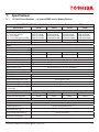
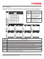
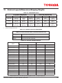
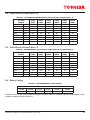
11.1 15-30kVA Specications – w/ Internal MBS and/or Battery Backup ............................................................57
11.2 Estimated Runtime on Internal Batteries – 15-30kVA ..................................................................................61
11.3 15-30kVA Specications – w/ External Battery Backup ...............................................................................61
11.4 15–30kVA Eciency vs. Load (Typical) .......................................................................................................65
11.5 15–30kVA Thermal Loss vs. Load (Typical) .................................................................................................65
11.6 50kVA Specications – w/ Internal Battery Backup .....................................................................................66
11.7 Estimated Runtime on Internal Batteries – 50kVA .......................................................................................68
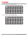
11.8 50–100kVA Specications – w/ External Battery Backup ............................................................................69
11.9 50–100kVA Eciency vs. Load (Typical, No Transformer) ..........................................................................72
11.10 50–100kVA Thermal Loss vs. Load (Typical) .............................................................................................72
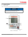
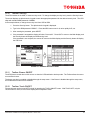
12 Operator Interface .................................................................................................................... 73
12.1 Operator Controls ........................................................................................................................................73
12.2 Operator Controls – Light Emitting Diodes (LED) ........................................................................................74
12.3 Operator Controls ........................................................................................................................................75
12.4 Touch Screen Display ..................................................................................................................................76
12.5 Header Bar ..................................................................................................................................................77
12.6 Footer Bar ....................................................................................................................................................77
12.7 Touchscreen Data and Controls ..................................................................................................................78
12.8 Quick Access Toolbar ..................................................................................................................................79
12.9 4400 Menu Tree .........................................................................................................................................80
12.10 Toolbar: Security ........................................................................................................................................81
12.11 Toolbar: Buzzer ON/OFF ...........................................................................................................................81
12.12 Toolbar: Touch ON/OFF .............................................................................................................................81
12.13 Toolbar: QUICK VIEW ON/OFF .................................................................................................................82
12.14 Tab: Main – RUN/STOP .............................................................................................................................83
12.15 Tab: Monitor ...............................................................................................................................................85
12.16 Tab: Setup .................................................................................................................................................87
12.17 Setup: Calibrating the Touchscreen ...........................................................................................................89
12.18 Tab: Record ...............................................................................................................................................90
12.19 Tab: Help ...................................................................................................................................................91
12.20 4400 Parameter Denitions .......................................................................................................................91
12.21 System Fault Messages ............................................................................................................................92
12.22 System Warning Messages .......................................................................................................................93
12.23 System Mode Messages ...........................................................................................................................94
12.24 System Status Messages ..........................................................................................................................94
13 UPS Operation .......................................................................................................................... 96
13.1 Standard UPS Operation (No Internal MBS) ...............................................................................................96
13.4 Battery Low Voltage Tolerances ................................................................................................................100
13.5 Audible Alarm Functions ............................................................................................................................101
14 Options .................................................................................................................................... 102
14.1 Replacement Air Filters .............................................................................................................................102
14.2 Remote Monitoring System – RemotEye 4 ...............................................................................................102
14.3 Remote System Monitoring – Remote Radar ............................................................................................102
15 External Layouts/Dimensions/Shipping Weights ................................................................ 103
Appendix A – Dimensional Drawings ............................................................................................ 105
..................................................................111

iii
4400 Series Installation and Operation Manual – 64527-010
Appendix C – Installation Planning Guide .....................................................................................118
Appendix D – Internal XFMR Unit Input/Output Cabling Guide .................................................. 121
D.1 – UPS Power Lug Cable Capacity and Torque Specications ........................................................................121
D.2 – Input Cable Size for 3-Phase/4-Wire + G ....................................................................................................121
D.3 – Output/Bypass Cable Size for 3-Phase/4-Wire + G .....................................................................................122
D.4 – Cable Size for 3-Phase/3-Wire + G .............................................................................................................123
D.5 – Cable Size for 3-Phase/3-Wire + G .............................................................................................................123
D.6 – Battery Cabling ............................................................................................................................................123
D.7 – Input Transformer Current for Given Input Voltage ......................................................................................124
D.8 – Output Transformer Current for Given Output Voltage ................................................................................124
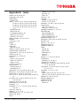
Appendix E – Index ......................................................................................................................... 125

This page left intentionally blank

1
4400 Series Installation and Operation Manual – 64527-010
1 Introduction
This manual provides information on how to safely operate your 4400 Series Uninterruptible Power System (UPS). This
manual includes a section of general safety instructions that describes the warning labels and symbols that are used
throughout the manual. Read the manual completely before installing, operating, or performing maintenance on this
equipment.
Qualied personnel should read this manual carefully before transporting, installing, and wiring the UPS. In addition they
have a thorough understanding of the information provided in the chapters titled:
• General Safety Instructions
• Important Safety Instructions
• Safety Precautions
• Installation Precautions
Read this 4400 Series Operation Manual for important instructions on operating the UPS. This manual and the accompanying
drawings should be considered a permanent part of the equipment and should be readily available for reference and review.
Keep the Installation Manual and the Operation Manual near the UPS for necessary reference.
Dimensions shown in the manual are in metric and/or the English customary equivalent.
SAVE THESE INSTRUCTIONS

24400 Series Installation and Operation Manual – 64527-010
2 General Safety Instructions
DO NOT attempt to transport, install, operate, maintain or dispose of this equipment until you have read and understood all
of the product safety information provided in this manual.
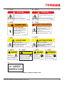
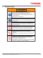
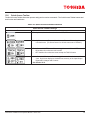
2.1 Symbols
The symbols listed below are used throughout this manual. When symbols are used in this manual they will include important
safety information that must be carefully followed.
Safety Alert Symbol indicates that a potential personal
injury hazard exists.
Prohibited Symbol indicates DO NOT take action.
Mandatory Symbol indicates that the following instruction
is required.
Ground Symbol indicates the location of the equipment
grounding conductor.
Electrical – Voltage & Shock Hazard Symbol
indicates parts inside may cause electric shock.
Explosion Hazard Symbol indicates parts may
explode.

3
4400 Series Installation and Operation Manual – 64527-010
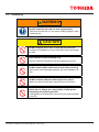
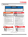
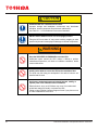
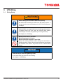
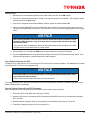
2.2 Signal Words
The signal words listed below are used throughout this manual. When the words DANGER, WARNING, CAUTION and
ATTENTION are used in this manual they will include important safety information that must be carefully followed.
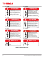
The word DANGER in capital letters preceded
by the safety alert symbol indicates that an
imminently hazardous situation exists, and if not
avoided will result in loss of life or serious injury
to personnel.
The word WARNING in capital letters preceded by
the safety alert symbol indicates that a potentially
hazardous situation exists, and if not avoided
may result in loss of life or serious injury to
personnel.
The word CAUTION in capital letters preceded by
the safety alert symbol indicates that a potentially
hazardous situation exists, and if not avoided may
result in minor or moderate injury.
The word NOTICE in capital letters without
the safety alert symbol indicates a potentially
hazardous situation exists, and if not avoided may
result in equipment and property damage.
NOTICE
CAUTION
WARNING
DANGER
2.3
Installation, operation, and maintenance shall be performed by Qualied Personnel Only. A Qualied Person is one
that has the skills and knowledge relating to the construction, installation, operation, and maintenance of the electrical
equipment described herein and has received safety training on the hazards involved (Refer to the latest edition of NFPA
70E for additional safety requirements).
Qualied Personnel shall:
• Have read the entire operation manual.
• Be familiar with the construction and function of the 4400 UPS, the equipment being driven, and the hazards involved.
• Be trained and authorized to safely energize, de-energize, ground, lockout/tagout circuits and equipment, and clear
faults in accordance with established safety practices.
• Be trained in the proper care and use of protective equipment such as safety shoes, rubber gloves, hard hats, safety
glasses, face shields, ash clothing, etc., in accordance with established safety practices.
• Be trained in rendering rst aid.
For further information on workplace safety visit www.osha.gov.
2.4 Factory Authorized Personnel
Factory authorized personnel have been factory trained and certied to install, service, and repair the UPS. Contact the
Toshiba Customer Support Center for assistance in locating the factory 4400-authorized personnel nearest you.

44400 Series Installation and Operation Manual – 64527-010
3 Important Safety Instructions
The following contains important instructions that should be followed during the installation, operation, and maintenance of
the 4400 Series UPS.
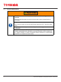
CAUTION
Misuse of this equipment could result in personal injury and/or equipment damage.
In no event will Toshiba Corporation be responsible or liable for either indirect or
consequential damage or injury that may come from the use of this equipment.
The UPS system output is NOT equipped with an over-current protection device, or an output disconnect at the
AC output. The user should provide circuit breakers between the UPS AC input (or Bypass input) and the power sources
and between the UPS output and the critical load input. The minimum device ratings are listed in “9.5 External Breakers”
on page 53
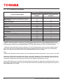
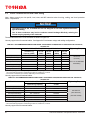
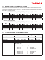
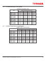
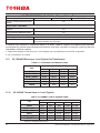
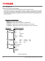
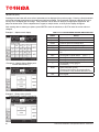
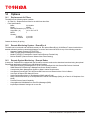
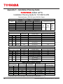
The maximum operating ambient temperature for the UPS is 104 °F (40 °C) at 0.9 PF.
If the UPS is exposed to the same ambient temperature as the DC backup supply, the maximum operating ambient
temperature is:
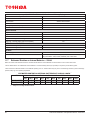
• Battery backup: 90 °F (32 °C) at 0.9 PF. Table 3.1 lists the nominal battery voltage.
TABLE 3.1: UPS NOMINAL BATTERY VOLTAGE
All kVA 288 Vdc 324 V

5
4400 Series Installation and Operation Manual – 64527-010
3.1 Unintended Usage
DANGER
Never use this UPS in any of the following applications:
a. Medical Operation Room Equipment
b. Life Support Equipment
c. Fire Prevention or Suppression Equipment
Use of this UPS in any of the above applications will result in serious personal injury or death.
WARNING
Always read all applicable regulations and standards for the specic application of this UPS.
Special precautions must be undertaken when this UPS is used in the following applications:
a. Nuclear Power Plants
b. Communications Equipment
c. Transportation Equipment
Always consult highly trained and qualied technicians in these applications.
Improper use of the UPS in any of the above applications may result in serious personal injury or death.
3.2 Disclaimer
IN NO EVENT WILL TOSHIBA CORPORATION BE RESPONSIBLE OR LIABLE FOR EITHER INDIRECT OR
CONSEQUENTIAL DAMAGE OR INJURY THAT MAY COME FROM THE MISUSE OF THIS EQUIPMENT. ANY
MODIFICATIONS WITHOUT AUTHORIZATION BY TOSHIBA COULD RESULT IN PERSONAL INJURIES, DEATH OR
DESTRUCTION OF THE UPS.
TOSHIBA RESERVES THE RIGHT TO MAKE CHANGES WITHOUT FURTHER NOTICE TO ANY PRODUCTS HEREIN
TO IMPROVE RELIABILITY, FUNCTION OR DESIGN. TOSHIBA DOES NOT ASSUME ANY LIABILITY ARISING OUT
OF THE APPLICATION OR USE OF ANY PRODUCT OR UPS DESCRIBED HEREIN; NEITHER DOES IT CONVEY ANY
LICENSE UNDER ITS PATENT RIGHTS, NOR THE RIGHTS OF OTHERS.

64400 Series Installation and Operation Manual – 64527-010
3.3 General Maintenance
WARNING
DO NOT remove the rear/side panels, or any sheet metal not designed to be
removed.
Removing rear/side panels may result in electric shock, burns, personal injuries or
UPS failure.
Keep the area around the UPS clean.
Use a vacuum cleaner to clean dust and foreign material the UPS. Keep the exterior
clean.
Only factory authorized personnel should perform internal general maintenance
on the UPS.
Contact the authorized Toshiba Customer Support Center or an authorized
Toshiba representative for information on proper disposal of UPS components.
It is illegal to dispose of certain components without conforming to environmental
regulations for industrial/commercial waste.

7
4400 Series Installation and Operation Manual – 64527-010
3.4 Transporting
WARNING
DO NOT tilt the UPS more than 10° from upright position.
Tilting the UPS more than 10° may cause crushing, trapping or other
personal injuries.
CAUTION
DO NOT transport, move, store, or place the UPS on its side.
Excessive force applied from heavy components inside may damage
the UPS.
Avoid vibration or shock exceeding 0.5 g.
Failing to observe this precaution may cause damage to the UPS.
Tools used to remove packaging materials may cause damage to the
UPS.
DO NOT install the UPS where water may fall on or enter it.
Water may cause electrical shock, personal injury or UPS failure.
DO NOT push or pull on the sides of the packaging or the
UPS to move it. Always use a crane, forklift, or pallet jack for
transporting and positioning the UPS.
Pushing/pulling on the sides of the unit to move it may result in damage
to the UPS.

84400 Series Installation and Operation Manual – 64527-010
4 Unpacking
4.1 General Instructions
Unpack the UPS indoors on a paved oor. The UPS should be as close as possible to its nal location. Allow enough space
for forklift operations to unpack the UPS from the packing crate. Then remove the crate. Properly dispose of the crate.
Points to observe:
• Retain all small articles during unpacking and installation.
• Make sure that exterior paint is not scratched and that the UPS cabinet is not damaged before uncrating.
• DO NOT damage the UPS when using tools to remove packaging materials.
• If provided, DO NOT remove the protective plastic sheet cover until installation.
• Do not remove the protective fan covers over the fans until UPS start up. The fan covers should be removed
by factory authorized personnel. Packing materials should be disposed by the appropriate means.
• Immediately report any abnormalities to Toshiba Customer Support Center or an authorized representative.
• Retain the packing rails for ooading the UPS from the shipping pallet, and for nal UPS installation.
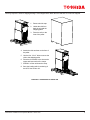
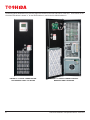
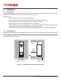
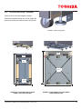
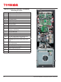
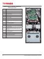
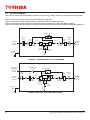
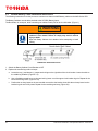
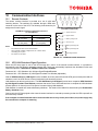
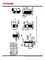
4.2 Unpack the 15-30kVA Model UPS (with Casters)
NOTE: The 4400 UPS is equipped with casters and leveling feet. It is attached to the shipping pallet by two un-
.
CAUTION
TOP HEAVY EQUIPMENT. THIS EQUIPMENT WILL TIP OVER EASILY
UNTIL FIXED IN PLACE.
Lift and move carefully, and only with adequate equipment and trained
personnel. IMPROPER LIFTING CAN RESULT IN INJURY OR DEATH.

9
4400 Series Installation and Operation Manual – 64527-010
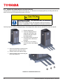
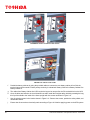
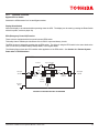
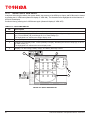
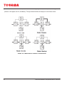
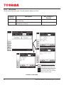
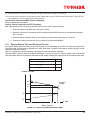
Carefully inspect the UPS for shipping damage. Units shipped within North America and NAFTA are shrink wrapped.
1. Remove shrink wrap.
2. Unbolt the rails from
both the unit and the
shipping pallet.
3. Place the rails on the
front of the pallet.
4. Attach the rails as shown to the front of
the pallet.
5 Use the four 1/2 x 3” bolts to secure the
rails to the shipping pallet.
6. Place the tie brackets in the slots at the
upper and lower ends of the ramps.
7 SLOWLY roll the unit down the ramp.
8. Save the loading rails for anchoring of
the UPS. See Section 8.3.
FIGURE 4.1: UNSHIPPING 15-30KVA UPS

10 4400 Series Installation and Operation Manual – 64527-010
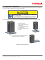
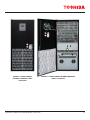
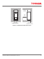
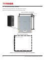
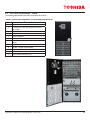
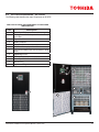
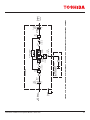
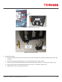
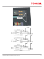
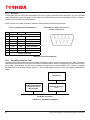
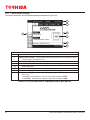
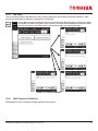
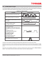
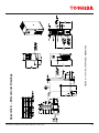
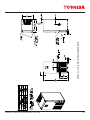
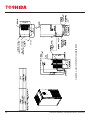
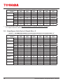
4.3 Unpack the 50kVA Model UPS (with Casters)
The 4400 UPS is equipped with casters and leveling feet. It is attached to the shipping pallet by unloading rails that can
double as oor anchors during nal placement of the UPS.
CAUTION
TOP HEAVY EQUIPMENT. THIS EQUIPMENT WILL TIP OVER EASILY
UNTIL FIXED IN PLACE.
Lift and move carefully, and only with adequate equipment and trained
personnel. IMPROPER LIFTING CAN RESULT IN INJURY OR DEATH.
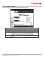
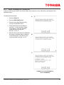
Carefully inspect the UPS for shipping damage. Units shipped within North America and NAFTA are shrink wrapped.
1. Remove shrink wrap.
2. Unbolt the Shipping rails on
each side of the base of the
UPS from both the unit and
the shipping pallet.
3. Place the two side (A) and one
center (B) rails on the front of
the pallet.
4. Use the six 1/2 x 3” bolts to
secure the rails to the shipping
pallet.
5. Place the tie brackets in the slots at the
upper and lower ends of the ramps.
6. SLOWLY roll the unit down the ramp.
7. Save the loading rails for anchoring the
UPS. See Section 8.3.
3
1
BA
A
6
FIGURE 4.2: UNSHIPPING 50KVA UPS
Page is loading ...
Page is loading ...
Page is loading ...
Page is loading ...
Page is loading ...
Page is loading ...
Page is loading ...
Page is loading ...
Page is loading ...
Page is loading ...
Page is loading ...
Page is loading ...
Page is loading ...
Page is loading ...
Page is loading ...
Page is loading ...
Page is loading ...
Page is loading ...
Page is loading ...
Page is loading ...
Page is loading ...
Page is loading ...
Page is loading ...
Page is loading ...
Page is loading ...
Page is loading ...
Page is loading ...
Page is loading ...
Page is loading ...
Page is loading ...
Page is loading ...
Page is loading ...
Page is loading ...
Page is loading ...
Page is loading ...
Page is loading ...
Page is loading ...
Page is loading ...
Page is loading ...
Page is loading ...
Page is loading ...
Page is loading ...
Page is loading ...
Page is loading ...
Page is loading ...
Page is loading ...
Page is loading ...
Page is loading ...
Page is loading ...
Page is loading ...
Page is loading ...
Page is loading ...
Page is loading ...
Page is loading ...
Page is loading ...
Page is loading ...
Page is loading ...
Page is loading ...
Page is loading ...
Page is loading ...
Page is loading ...
Page is loading ...
Page is loading ...
Page is loading ...
Page is loading ...
Page is loading ...
Page is loading ...
Page is loading ...
Page is loading ...
Page is loading ...
Page is loading ...
Page is loading ...
Page is loading ...
Page is loading ...
Page is loading ...
Page is loading ...
Page is loading ...
Page is loading ...
Page is loading ...
Page is loading ...
Page is loading ...
Page is loading ...
Page is loading ...
Page is loading ...
Page is loading ...
Page is loading ...
Page is loading ...
Page is loading ...
Page is loading ...
Page is loading ...
Page is loading ...
Page is loading ...
Page is loading ...
Page is loading ...
Page is loading ...
Page is loading ...
Page is loading ...
Page is loading ...
Page is loading ...
Page is loading ...
Page is loading ...
Page is loading ...
Page is loading ...
Page is loading ...
Page is loading ...
Page is loading ...
Page is loading ...
Page is loading ...
Page is loading ...
Page is loading ...
Page is loading ...
Page is loading ...
Page is loading ...
Page is loading ...
Page is loading ...
Page is loading ...
Page is loading ...
Page is loading ...
-
 1
1
-
 2
2
-
 3
3
-
 4
4
-
 5
5
-
 6
6
-
 7
7
-
 8
8
-
 9
9
-
 10
10
-
 11
11
-
 12
12
-
 13
13
-
 14
14
-
 15
15
-
 16
16
-
 17
17
-
 18
18
-
 19
19
-
 20
20
-
 21
21
-
 22
22
-
 23
23
-
 24
24
-
 25
25
-
 26
26
-
 27
27
-
 28
28
-
 29
29
-
 30
30
-
 31
31
-
 32
32
-
 33
33
-
 34
34
-
 35
35
-
 36
36
-
 37
37
-
 38
38
-
 39
39
-
 40
40
-
 41
41
-
 42
42
-
 43
43
-
 44
44
-
 45
45
-
 46
46
-
 47
47
-
 48
48
-
 49
49
-
 50
50
-
 51
51
-
 52
52
-
 53
53
-
 54
54
-
 55
55
-
 56
56
-
 57
57
-
 58
58
-
 59
59
-
 60
60
-
 61
61
-
 62
62
-
 63
63
-
 64
64
-
 65
65
-
 66
66
-
 67
67
-
 68
68
-
 69
69
-
 70
70
-
 71
71
-
 72
72
-
 73
73
-
 74
74
-
 75
75
-
 76
76
-
 77
77
-
 78
78
-
 79
79
-
 80
80
-
 81
81
-
 82
82
-
 83
83
-
 84
84
-
 85
85
-
 86
86
-
 87
87
-
 88
88
-
 89
89
-
 90
90
-
 91
91
-
 92
92
-
 93
93
-
 94
94
-
 95
95
-
 96
96
-
 97
97
-
 98
98
-
 99
99
-
 100
100
-
 101
101
-
 102
102
-
 103
103
-
 104
104
-
 105
105
-
 106
106
-
 107
107
-
 108
108
-
 109
109
-
 110
110
-
 111
111
-
 112
112
-
 113
113
-
 114
114
-
 115
115
-
 116
116
-
 117
117
-
 118
118
-
 119
119
-
 120
120
-
 121
121
-
 122
122
-
 123
123
-
 124
124
-
 125
125
-
 126
126
-
 127
127
-
 128
128
-
 129
129
-
 130
130
-
 131
131
-
 132
132
-
 133
133
-
 134
134
-
 135
135
-
 136
136
-
 137
137
-
 138
138


Toshiba 4400 series User manual
- Type
- User manual
Ask a question and I''ll find the answer in the document
Finding information in a document is now easier with AI
Related papers
Other documents
-
Eaton MT3400T Molded Case Circuit Breaker Accessory Trip Unit Operating instructions
-
Abestorm NeatyFresh Pro User manual
-
 OPTI-UPS DS10KC33II User manual
-
MGE UPS Systems Comet 150kVA User manual
-
 Shield T3 80kVA User manual
-
Tripp Lite TRIPP-LITE S3MT-100K600V S3MT-Series 3-Phase 100kVA Input Isolation Transformer 600V Delta to 208V Wye Operating instructions
-
-
Xtreme M90-20k80 User & Installation Manual
-
-
Garmin EDP70 User manual

