Page is loading ...

Instruction Manual Book
A6M ZERO
Item code: BH171.
Made in Vietnam.
OPTION ELECTRIC RETRACT GEAR (NOT INCLUDING).
ONLY INCLUDING OLEO STRUTS.
ALL BALSA - PLY WOOD CONSTRUCTION.
COVERED IN A HEAT-SHRINK FILM WITH PRINTED.
SPECIFICATION:
- Wingspan: 1,720 mm (67.72 in).
- Length: 1,375 mm (54.13 in).
- Weight: 4.4 - 4.6 kg (9.68 - 10.12lbs).
2
- Wing area: 46.5 dm .
2
- Wing loading: 94.62 g/dm .
- Servo mount: 42mm x 21mm.
- Wing type: Naca Airfoil.
- Spinner: 70mm.
- Gear type: Electric retract gear,
size: (92.2 x 51 x 30.6)mm (not included).
Oleo struts (included).
Parts listing required (not included):
- Radio: 06 channels.
- Servo: 07 servos.
- Engine: 75 - 95 2 strokes; 15 cc gas.
- Motor: Brushless outrunner 1200-2200W, 650KV.
- Propeller: Suit with your engine.
Recommended Motor and Battery set up (not included):
- Motor: RIMFIRE.60.
- Lipo cell: 6 cells 4,000-5,000mAh.
- Receiver battery: 6V/ 800-1200 mAh.
- ESC: 80A.
95% ALMOST READY TO FLY
Glow and EP

4Installing the Engine . . . . . . . . . . . . . . . . . . 18
4Installing the throttle . . . . . . . . . . . . . . . . . . 21
4Mounting the cowl. . . . . . . . . . . . . . . . . . . . . 22
4Installing horizontal stabilizer . . . . . . . . . . . . 24
4Installation the tail gear. . . . . . . . . . . . . . . . . 27
4Installing the rudder . . . . . . . . . . . . . . . . . . . 28
4Installing the switch, receiver and battery. . . 30
4Installing cockpit fuselage. . . . . . . . . . . . . . . 31
4Installing the wing to the fuselage . . . . . . . . 33
4Installing the spinner, propeller. . . . . . . . . . . 34
4Balancing . . . . . . . . . . . . . . . . . . . . . . . . . . . 36
4Lateral balance . . . . . . . . . . . . . . . . . . . . . . . 36
4Control throws . . . . . . . . . . . . . . . . . . . . . . . 36
4Pre-flight check. . . . . . . . . . . . . . . . . . . . . . . 36
4For your radio installation basic connection for
airplane and adjustment of servos. . . . . . . . . . . 37
4Main gear dimensional detail.. . . . . . . . . . . . 38
4Symbols used throughout this instruction
manual, comprise: . . . . . . . . . . . . . . . . . . . . . . . . 2
4Warranty . . . . . . . . . . . . . . . . . . . . . . . . . . . . . 3
4Disclaimer. . . . . . . . . . . . . . . . . . . . . . . . . . . . 3
4Suggestion . . . . . . . . . . . . . . . . . . . . . . . . . . . 3
4Note . . . . . . . . . . . . . . . . . . . . . . . . . . . . . . . . 3
4Safety precaution . . . . . . . . . . . . . . . . . . . . . . 3
4Parts listing (not included). . . . . . . . . . . . . . . . 4
4Tools & supplies needed. . . . . . . . . . . . . . . . . 4
4ing plastic light. . . . . . . . . . . . . . . . . . . . . . . 6
4Installing the ailerons and flaps. . . . . . . . . . . . 6
4Installing the ailerons and flaps servos. . . . . . 7
4Installing the control horns and linkages . . . . 8
4Installing the wheel well . . . . . . . . . . . . . . . . 10
4Installing main gear. . . . . . . . . . . . . . . . . . . . 11
4Installing the fuselage servos . . . . . . . . . . . . 15
4Installing the engine mount. . . . . . . . . . . . . . 16
4Installing the electric motor (EP version) . . . 16
W
INSTRUCTION MANUAL A6M ZERO Item code: BH171
TABLE OF CONTENTS
Academy of Model Aeronautics: If you are not already a member of the AMA, please join! The AMA is the
governing body of model aviation and membership provides liability insurance coverage, protects modelers’
rights and interests and is required to fly at most R/C sites.
Academy of Model Aeronautics
5151 East Memorial Drive Muncie IN 47302-9252
Tele. (800) 435-9262
Fax. (765) 741-0057
Or via the Internet at: http://www.modelaircraft.org
SINCE 1939
2
Cut off excess.
B
Apply epoxy glue.
Apply threadlocker
(screw cement).
C.A
Apply instant glue
(C.A glue, super glue).
Cut off shaded portion
carefully.
Assemble left and right
sides the same way.
Must be purchased
separately!
Ensure smooth, non-binding
movement when assembling.
Warning!
Set all scerws securely. If they come off during
flight you will lose control of your aircraft!
Pay close attention here.
Drill holes using the stated.
(in this case 1.5mm ).
1
.5mm
Take particular care here.
The number of times
the same way Assembly
(in this case twice).
2
Symbols used throughout this instruction manual, comprise:

3
To avoid scratching your new airplane, do not
unwrap the pieces until they are needed for assembly.
Cover your workbench with an old towel or brown paper,
both to protect the aircraft and to protect the table. Keep
a couple of jars or bowls handy to hold the small parts
after you open the bag.
SUGGESTION
Please trial fit all the parts. Make sure you have the
correct parts and that they fit and are aligned properly
before gluing! This will assure proper assembly. is
hand made from natural materials, every plane is unique
and minor adjustments may have to be made. However,
you should find the fit superior and assembly simple.
The painted and plastic parts used in this kit are fuel
proof. However, they are not tolerant of many harsh
chemicals including the following: paint thinner, C/A glue
accelerator, C/A glue debonder and acetone. Do not let
these chemicals come in contact with the colors on the
covering and the plastic parts.
Caution: This model is not a toy!
If you are a beginner to this type of powered model,
please ask an experienced model flyer for help and
support. If you attempt to operate the model without
This kit
NOTE:
Black Horse Model guarantees the component
parts in this kit to be free from defects in both material
and workmanship at the date of purchase by the
purchaser.
This warranty does not cover cosmetic damage or
damage due to acts of God, accident, misuse, abuse,
negligence, commercial use, or modification of or to any
part of the Product.
This warranty does not cover damage due to
improper installation, operation, maintenance, or
attempted repair by anyone other than Black Horse
Model.
Return only the component part that is defective in
materials or workmanship. Please pack the unit carefully
and insure it, as this warranty does not cover loss or
damage in transit.
WARRANTY
DISCLAIMER
Read this disclaimer carefully before using this
product. Please strictly follow the instruction manual to
assemble and use this.
In that Black Horse Model has no control over the
final assembly or material used for final assembly, black
Horse Model is not responsible for loss of use, or other
incidental or consequential damages.
Furthermore, Black Horse Model cannot be held
liable for personal injury or property damage caused by
the use or misuse of Black Horse Model products. By the
act of using the user-assembled products, the user
accepts all resulting liability.
knowing what you are doing you could easily injure
yourself or somebody else. Please keep your safety and
well-being in mind at all times.
Important: Before you start construction
Even if you have built a large number of RC
modelsplease read right through these instructions and
check all the kit components against the parts list. We
have taken great trouble to keep construction as simple
as possible, without making any compromises in the area
of safety.
Note regarding the film covering
Minor creases or bubbles may develop in the film
covering due to major fluctuations in weather conditions
(temperature, humidity etc.); in rare cases you may even
find a slight warp in a component. These minor faults are
in the nature of film-covered built-up wooden structures,
and can easily be corrected using a heat gun, as
commonly used for modelling.
Creases: Blow warm air over the area and rub down
with a soft cloth.
Wing wrap: Hold the panel twisted gently in the
opposite direction to the wrap, and apply warm air to
remove the creases from the covering.
Caution! do not heat the film more than is absolutely
necessary. If the air or the iron is too hot, the film may melt
and holes may be formed.
This model is highly pre-fabricated and can be built
in a very short time. However, the work which you have to
carry out is important and must be done carefully. The
model will only be strong and fly well if you complete your
tasks competently - so please work slowly and
accurately.
When self-tapping screws have to be screwed
into wood, apply a little white glue to prevent them
shaking loose: just squirt white glue into the hole
and fit the screw
§This model is not a toy and pilots must be over the
age of 14.
§Be sure that no other flyers are using your radio
frequency.
§Do not smoke near fuel.
§Store fuel in a cool, dry place, away from children
and pets.
§Wear safety glasses.
§The glow plug clip must be securely attached to the
glow plug.
§Do not flip the propeller with your fingers.
§Keep loose clothing and wires away from the
propeller.
§Do not start the engine if people are near. Do not
stand in line with the side of the propeller.
§Make engine adjustments from behind the propeller
only. Do not reach around the spinning propeller.
§Moisture causes damage to electronics. Avoid water
exposure to all equipment not specifically designed and
protected for this purpose.
SAFETY PRECAUTION:
INSTRUCTION MANUAL A6M ZERO Item code: BH171

Wire cutters.
Hex Wrench.
Threadlocker
(screw cement).
Hand or
electric drill.
cm
12345678910
Straight edge ruler.
Some more tools.
Assorted drill bits.
Masking tape.
Paper towels.
Rubbing alcohol
90° square or builder's triangle.
Screw driver
Medium C/A glue
EPOXY A
EPOXY B
30 minute epoxy.
5 minute epoxy.
Modeling knife.
2 bender plier
TOOLS & SUPPLIES NEEDED.
4
INSTRUCTION MANUAL A6M ZERO Item code: BH171
Size: (92.2 x 51 x 30.6)mm.
2 pcs.
Propeller. Suit with your engine.
ESC
MOTOR
Size: 60 ..... 1 pcs.
ESC: 80A ....... 1 pcs.
PARTS LISTING (NOT INCLUDED).
Servo extension leads.
................. pcs. 3
190mm ..... 2 pcs.
BATTER
Y
LiPo. 6S - 22.2V- 4000-5000mAh.
1 Packs
7 servos. Size: (39.9 x 20.1 x 38.1)mm.
Torque: 4.8V (5.18kg/cm), 6V ( 6.48 kg/cm).
Engine: 15cc Gas.

5
INSTRUCTION MANUAL A6M ZERO Item code: BH171
: Fuselage
: Wing panel ( )
: Horizontal stabilizer.
: Rudder.
: Cowling.
: Spinner.
: W a, 7b)
: Aluminium wing dihedral brace(19x418mm).
: Cockpit fuselage (9a, 9b:
: Pilot, 9d: Top hatch fuselage).
(10a, 10b)
.
2a, 2b .
ing plastic light (7 .
Plastic - engine mount .
: Wood - motor mount
Canopy,
9c
:
1
2
3
4
5
6
7
8
7
9
11
10
1
3
4
5
2a
7a
2b
7b
8
12
13
14
15
:
: Wheels (85mm).
Tail gear set
: Fuel Tank (17a: Clunk,
17b: Stopper (three line)).
: Landing gear mount.
: Plastic bomb wing.
Door mounting wheel (12a, 12b)
: Wheel well (13a, 13b).
: Main gear struts.
:
: Antenna.
16
17
18
19
20
17a
17b
17
4mm Flat washer
- - - - - - - - - - 4
4mm Spring Washer
- - - - - - - - - - 8
4mm Nut - - 8
500mm Pushrod wire
- - - 1
4x30mm Cap Screw
- - 8 - - -
Connector - - - 1
10b
10a
10
- - - - - 4
10x5mm Aluminum
- - - - - 4
10x50mm Aluminum
4mm Flat washer
- - - - - 8
4mm Spring Washer
- - - - - 8
Mount Nut
- - - - - 4
4mm Flat washer
- - - - - 4
- - 4
4x70mm Cap Screw
4x20mm Cap Screw
- - 4 - - -
11
19
- - 2
3mm Colar
3x15mm Screw
- - - - - 2
16
Horn
- - - 7
- - - 7
Flaslink
3x15mm Screw
- - - - 6
2x10mm Screw
- - - - 16
- - - - - 1
100mm Push rod
- - 5
M2
- - 7
- - 7
2mm Nut
6x74mm
- - - 2
800mm Push rod
- - 3
40mm Silicone tube
- - 1
3x12mm Screw
- - - - 4
3x6mm Button Head Cap Screw
- - - - - - 2
5mm Colar
5x40mm Socket Head Cap Screw
- - - - - - - - - 2
3x15mm Screw
- - - - 8
- - - - - - - - - 8
- - - - - - - - - 4
13a
13b
18
14
12a
12b
5mm Flat washer
- - - - - 2
9
9a
9b
9c
9d
20
15
85mm
- - - 2
6
3x12mm Screw
70mm

WING PLASTIC LIGHT
INSTALLING THE AILERONS AND FLAPS.
INSTRUCTION MANUAL A6M ZERO Item code: BH171
Flap
Aileron
Bottom view
6
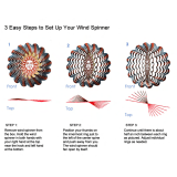
2) Apply drops of thin CA to the top and bottom of
each hinge. Do not use CA accelerator. After the CA
has fully hardened, test the hinges by pulling on the
aileron.
Temporary pin to
keep hinge centered.
1) Test fit the ailerons to the wing with the hinges. If
the hinges don’t remain centered, stick a pin through
the middle of the hinge to hold it in position.
1
2
C.A
C.A
Secure nylon hinges with instant glue, being
careful not to glue the wing and aileron together.
Align the center line of main wing with aileron.
1
2
Warning!
Make certain the hinges are
adequately secured with glue. if they come loose in
flight accidents may result.
C.A
2

INSTRUCTION MANUAL A6M ZERO Item code: BH171
1. Install the rubber grommets and brass eyelets
onto the aileron servos.
2. Using a modeling knife, remove the covering
from over the pre-cut servo arm exit hole on the
aileron servo tray / hatch. This hole will allow the
servo arm to pass through when installing the aileron
pushrods.
3. Place the servo into the servo tray. Center the
servo within the tray and drill 1.5mm pilot holes
INSTALLING THE AILERONS AND FLAPS SERVOS
through the block of wood for each of the four
mounting screws provided with the servo.
4. Using the thread as a guide and using masking
tape, tape the servo lead to the end of the thread:
carefully pull the thread out. When you have pulled
the servo lead out, remove the masking tape and the
servo lead from the thread.
5. Place the servo into the servo tray/ hatch into the
servo box on the bottom of the wing and drill 1.5mm
pilot holes through the tray and servo box for each of
the four mounting screws. Secure the servo tray in
place using the mounting screws provided.
6. Repeat step # 2 - # 5 to install the second aileron
servo in the opposite wing half.
Bottom view
For Aileron servo.
For Flap servo.
o
60
Flap
o
90
Aileron
approx.16mm
2mm
4
Aileron and
flap servos.
4
2x10mm Screw
2
For Flap.
For Aileron.
1.5mm
2 mm
2
For Flap.
For Aileron.
Screw
1.5mm
1.5mm
7

2 x 10mm Screw
- - - - 16
Warning!
Tie the string.
Pull out servo cord with string.
1
2
Bottom view
2x10mm
1
2
For Aileron.
INSTRUCTION MANUAL A6M ZERO Item code: BH171
INSTALLING THE CONTROL HORNS AND LINKAGES.
1) Working with the aileron linkage for now, thread
one nylon clevis at least 14 turns onto one of the
2mm x 180mm threaded wires.
2) Attach the clevis to the outer hole in the control
horn. Install a silicone tube on the clevis.
3) Locate one nylon servo arm, and using wire
cutters, remove all but one of the arms. Using a
2mm drill bit, enlarge the third hole out from the
center of the arm to accommodate the aileron
pushrod wire.
4) Plug the aileron servo into the receiver and
center the servo. Install the servo arm onto the
servo. The servo arm should be perpendicular to
the servo and point toward the middle of the wing.
5) Center the aileron and hold it in place using a
couple of pieces of masking tape.
6) With the aileron and aileron servo centered,
carefully place a mark on the aileron pushrod wire
where it crosses the hole in the servo arm.
7) Using pliers, carefully make a 90 degree bend
down at the mark made. Cut off the excess wire,
leaving about 6mm beyond the bend.
8) Insert the 90 degree bend down through the
hole in the servo arm. Install one nylon snap
keeper over the wire to secure it to the arm. Install
the servo arm retaining screw and remove the
masking tape from the aileron.
9) Repeat step # 4 - # 8 to install the second
aileron linkage. After both linkages are completed,
connect both of the aileron servo leads using a Y-
harness you have purchased separately.
Bottom view
100mm Push rod
- - 4
M2
- - - 4
- - - 4
Horn
- - - 4
- - - 4
Flaslink
2mm Nut
8
B
Horn
4
2.2mm

INSTRUCTION MANUAL A6M ZERO Item code: BH171
9
Bottom view
Flaslink
Push rod
4
2
Mark the spot to attach
o
Bend 90
1
2
Cut
Silicone tube
5mm
Silicone Tube
M2
2mm Nut
Servo arm
Push rod
1
6mm

* Using a modeling knife,
carefully remove the film covering
from the gear tray. Make sure that
you do not remove any wood.
INSTALLING THE WHEEL WELL
10
INSTRUCTION MANUAL A6M ZERO Item code: BH171
Top view
C.A
Wing bottom view
Wheel well
5mm
Cut the plastic

INSTRUCTION MANUAL A6M ZERO Item code: BH171
INSTALLING MAIN GEAR
11
ELECTRIC NOT INCLUDED.
2 pcs.
43.70
30.70
41.00
51.00
4.20
30.60
92.20
24.10
48.50
2.50
9.75
5.10
21.00
12.00
ELECTRIC GEAR DIMENSIONAL DETAIL (mm)
3x6mm Button Head Cap Screw
- - - - - - 2
5mm Colar
5x40mm Socket Head Cap Screw
- - - - - - - - - 2
3x15mm Screw
- - - - 8
ONLY INCLUDING OLEO STRUTS.
Landing gear mount.
85mm Wheels.
- - - - - - - - - 8
- - - - - - - - - 4
5mm Flat washer
- - - - - 2
5x40mm
5mm Washer
5mm Collar
3x6mm
4x4mm
Secure
C.A

INSTRUCTION MANUAL A6M ZERO Item code: BH171
12
THERE ARE TWO OPTIONS:
OPTION 1: MAIN GEAR STRUTS
Screw
3x15mm
2
.5mm
Bottom view

INSTRUCTION MANUAL A6M ZERO Item code: BH171
OPTION 2: ELECTRIC GEAR RETRACTS
Screw
2
Bottom view
2
.5mm
3x15mm
2
Bottom view
2
Screw the gear in position
13
5mm

Top view
INSTRUCTION MANUAL A6M ZERO Item code: BH171
14
Bottom view

INSTALLING THE FUSELAGE SERVOS
1) Install the rubber grommets and brass collets into the
elevator, rudder and throttle servos. Test fit the servos into
the servo tray. Trim the tray if necessary to fit your servos.
2) Mount the servo to the tray using the mounting screws
provided with your radio system.
15
INSTRUCTION MANUAL A6M ZERO Item code: BH171
o
90
2
o
90
approx.16mm
2mm
approx.16mm
2mm
Fuselage top side
Rudder servo
Throttle servo
Elevator servo

INSTALLING THE ENGINE MOUNT
There are two options:
1. Electric motor
2. Engine mount.
OPTION 1: ELECTRIC MOTOR (EP VERSION)INSTALLING THE
INSTRUCTION MANUAL A6M ZERO Item code: BH171
- - - - - 4
10x5mm Aluminum
- - - - - - - 4
10x50mm Aluminum
4mm Flat washer
- - - - - - - - - 8
4mm Spring Washer
- - - - - - - - - 8
Mount Nut
- - - - 4
4mm Flat washer
- - - - - - - - - 4
- - - 4
4x70mm Cap Screw
4x20mm Cap Screw
- - 4 - - -
4mm Spring washer
4mm Flat washer
10x5mm
4x20mm Screw
16

INSTRUCTION MANUAL A6M ZERO Item code: BH171
ESC
17
4mm Spring washer
4mm Flat washer
4x70mm Screw
Zip tie
4mm Flat washer
10x50mm
Fuselage top side
ESC
ESC
Battery

Installing the engine mount, fuel tank
OPTION 2: INSTALLING THE ENGINE
INSTRUCTION MANUAL A6M ZERO Item code: BH171
4mm Flat washer
- - - - - - - - - - 4
4mm Spring Washer
- - - - - - - - - - 8
4mm Nut - - 8
500mm Pushrod wire
- - - 1
4x30mm Cap Screw
- - 8 - - -
Engine mount.
Size 60.
4mm Spring washer
4mm Flat washer
4x30mm Screw
1) The stopper has been pre-assembled at the factory.
2) Using a modeling knife, cut one length of silicon fuel
line (the length of silicon fuel line is calculated by how
the weighted clunk should rest about 8mm away from
the rear of the tank and move freely inside the tank).
Connect one end of the line to the weighted clunk and
the other end to the nylon pick up tube in the stopper.
3) Carefully bend the second nylon tube up at a 45
degree angle (using a cigarette lighter). This tube will
be the vent tube to the muffler.
4) Carefully bend the third nylon tube down at a 45
degree angle (using a cigarette lighter). This tube will
be vent tube to the fueling valve.
When the stopper assembly is installed in the
tank, the top of the vent tube should rest just below
the top surface of the tank. It should not touch the top
of the tank.
5) Test fit the stopper assembly into the tank. It may
be necessary to remove some of the flashing around
the tank opening using a modeling knife. If flashing is
present, make sure none of it falls into the tank.
6) When satisfied with the alignment of the stopper
assembly tighten the 3mm x 20mm machine screw
until the rubber stopper expands and seals the tank
opening. Do not over tighten the assembly as this
could cause the tank to split.
18

INSTRUCTION MANUAL A6M ZERO Item code: BH171
Fuel tank
Zip tie
To carburetor
fuel inlet
(see front view of fuel tank). Insert and tighten the screw.
Be sure to equip
air vent pipe.
Tubing for
re-fuelling
Not included.
Tygon tubing (Gas). And
silicone tubing (Methanol).
5mm
Silicone tube
Foam ring
Fuel tank
7) Using a modeling knife, cut 3 lengths of fuel line.
Connect 2 lines to the 2 vent tubes and 1 line to the
fuel pickup tube in the stopper.
8) Feed three lines through the fuel tank
compartment and through the pre-drilled hole in the
firewall. Pull the lines out from behind the engine,
while guiding the fuel tank into place. Push the fuel
tank as far forward as possible, the front of the tank
should just about touch the back of the firewall.
Blow through one of the lines to ensure the fuel lines
have not become kinked inside the fuel tank
compartment. Air should flow through easily.
Do not secure the tank into place permanently
until after balancing the airplane. You may need to
remove the tank to mount the battery in the fuel tank
compartment.
9. Secure the fuel tank.
INSTALLING THE THROTTLE PUSHROD
* Locate the long piece of wire used for the throttle pushrod. One end of the wire has been pre-bend in to a "Z"
bend at the factory. This "Z" bend should be inserted into the throttle arm of the engine when the engine is fitted
onto the engine mount. Fit the engine to the engine mount using the screws provided.
19

INSTRUCTION MANUAL A6M ZERO Item code: BH171
Pushrod Gas
20
4mm Nut
4mm Spring Washer
4x30mm
Screw
125mm
Electric Power
Pushrod Gas
/