Page is loading ...

CABINET VENT (VS-CV) INSTALLATION INSTRUCTIONS
1. Determine an appropriate location for the unit. The units are typically installed on the sides or the back of a
cabinet or enclosure and typically higher in the cabinet where amplifiers and receivers are located. Ensure that no
shelves or equipment will obstruct the unit once installed.
2. Drill a 3 1/8” (79mm) or 3 1/4” (80mm) hole once the proper position has been determined.
3. Determine if it is best for the unit to draw air from the cabinet (exhaust), or push air in (intake) - by default the unit
draws air out of the cabinet or enclosure and is appropriate for most applications. It may be preferable to blow air
into the cabinet and straight onto the equipment if the cabinet is not fully enclosed or there are several openings
that cannot be blocked in the enclosure. See instructions below on how to reverse the direction of the fan.
4. Slide the unit into the hole and secure with 4 screws. It is recommended to pre-drill pilot holes for the screws in
wood and is required for metal.
5. Determine the best route to run the power supply for connecting to
the fan unit and secure.
6. Connect the Fan Unit power wire to a Universal Power Supply
ensuring that polarity is correct – see diagram. The fan can be run
full time or powered by a switched power outlet on the back of the
amplifier, receiver, or another switching power unit.
7. Adjust the voltage on the Power Supply and operate between 4.5
and 9VDC for normal applications or 9 to 12VDC for more
demanding situations. The unit will be audible with these settings.
Adjust so the units operate quietly but if running at lower voltages
and if powering multiple units with one power supply, ensure the unit
restarts when power is disconnected and then reconnected.
Notes
¾ This unit can also be used with any Cool Components Inc. Temperature
Controller to provide control based on the temperature in the cabinet or
enclosure.
¾ For good measure, the shelving in cabinets should be designed as in the
diagram to the right. This provides for easier wiring management and airflow.
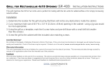
Fan Reversal Instructions
1. Pull the fan from the bracket using a flat tip screwdriver under one side of
the fan and gently pry the fan upwards until the mounts release. Do not force it, the mounts will release by
applying minimal force. (Figure 1)
2. Repeat this procedure on the opposite side of the fan to release the remaining mounts. (Figure 2)
3. Check desired direction of airflow which is indicated by an arrow on the side of the fan. (Figure 3) Also note
the desired position of the power wire (default is downward). Now place the fan over the fan mounts.
4. Install the fan by pulling the mounts though the fan mounting holes until the mount is properly seated (pulls
through the fan to reach the ‘stop’). (Figure 4)
5. Once the fan is attached, you may trim the rubber fan mounts if desired. This will however prohibit any
reversal of the fan in the future.
Figure 1: Pry Fan from Mount Figure 2: Remove both sides Figure 3: Check airflow direction Figure 4: Reattach fan

VERY IMPORTANT
Our products are intended to increase air flow around components which includes individual
components as well as cabinets, enclosures, and other areas where equipment is present.
It is important to follow all manufacturer recommendations for appropriate clearances around
components and not create a situation where equipment can potentially be damaged from heat
accumulations.
Cool Components, Inc. will not be responsible for components that are damaged under any circumstance including
failure of the cooling products. It is the installer’s responsibility to ensure products are installed in a manner where
damage will not occur even if the cooling products fail.
Unit Not Working?
Do not Return Damaged or Defective Products to Point of Purchase. If the unit arrived non-functional or
damaged, we will resolve the issue quickly and hassle-free. Proof of Purchase may be required.
Contact us on the web at: www.coolcomponents.com/warranty
Warranty Information
This unit is guaranteed to be free of defects for a period of one year from the date of purchase. This
warranty excludes damage caused by misuse or for applications other than the intended use of the
products.
Feedback
We truly value feedback on this and all of our products. We strive to provide the best products possible
so it is important that we learn from our customers. If you have any ideas or suggestions that could
improve this or any of our other products, please let us know. Thank you in advance for sharing your
experience. Please send feedback to
/