Titan Advantage EXP2255 Owner's manual
- Category
- Paint Sprayer
- Type
- Owner's manual
This manual is also suitable for

Model Numbers:
0552007 Stand
0552008 Upright Cart
0552009 Lowboy Cart
Printed in U.S.A.
1208 • © SprayTECH. All Rights Reserved. Form No.0552801A
NOTE: This manual contains important warnings and
instructions. Please read and retain for reference.
SprayTECH
1770 Fernbrook Lane
Minneapolis, MN 55447
Technical Assistance/
Order Entry:
Fax - Technical Assistance:
Fax - Order Entry:
1-800-526-5362
1-800-525-9501
1-800-528-4826
www.spraytechinc.com
EPX2255
Advantage Series
Piston Pump
Owner’s Manual
Do not use this equipment
before reading this manual!

2 © SprayTECH. All rights reserved.
Important Safety Information · Read all safety information before
operating the equipment. SAVE THESE INSTRUCTIONS.
This symbol indicates a hazardous situation,
which, if not not avoided could result in death or
serious injury.
To reduce the risks of fire or explosion, electrical
shock and the injury to persons, read and
understand all instructions included in this manual.
Be familiar with the controls and proper usage of
the equipment.
HAZARD: Injection injury
A high pressure paint stream produced by this
equipment can pierce the skin and underlying
tissues, leading to serious injury and possible
amputation. See a physician immediately.
DO NOT TREAT AN INJECTION INJURY AS A SIMPLE
CUT! Injection can lead to amputation. See a physician
immediately.
The maximum operating range of the sprayer is 3100 PSI / 21.4
MPa uid pressure.
PREVENTION:
• NEVER aim the gun at any part of the body.
• Do not aim the gun at, or spray any person or animal.
• NEVER allow any part of the body to touch the uid stream.
DO NOT allow body to touch a leak in the uid hose.
• NEVER put your hand in front of the gun. Gloves will not
provide protection against an injection injury.
• ALWAYS lock the gun trigger, shut the pump off, and
release all pressure before servicing, cleaning the tip or
guard, changing tip, or leaving unattended. Pressure will
not be released by turning off the motor. The PRIME/
SPRAY valve or pressure bleed valve must be turned to
their appropriate positions to relieve system pressure.
Refer to the PRESSURE RELIEF PROCEDURE
described in this manual.
• ALWAYS keep the tip guard in place while spraying. The
tip guard provides some protection but is mainly a warning
device.
• ALWAYS remove the spray tip before ushing or cleaning
the system.
• Paint hose can develop leaks from wear, kinking and
abuse. A leak can inject material into the skin. Inspect
the hose before each use. Do not use hose to lift or pull
equipment.
• NEVER use a spray gun without a working trigger lock and
trigger guard in place.
• All accessories must be rated at or above 3100 PSI / 21.4
MPa. This includes spray tips, guns, extensions, and hose.
• Do not leave the unit energized or under pressure while
unattended. When the unit is not in use, turn off the unit and
relieve the pressure in accordance with the PRESSURE
RELIEF PROCEDURE described in this manual.
• Verify that all connections are secure before operating the
unit. Unsecured parts may eject at great force or leak a
high pressure uid stream causing severe injury.
• Always engage the trigger lock when not spraying. Verify
the trigger lock is functioning properly.
NOTE TO PHYSICIAN:
Injection into the skin is a traumatic injury. It is
important to treat the injury as soon as possible. DO
NOT delay treatment to research toxicity. Toxicity is a
concern with some coatings injected directly into the
blood stream. Consultation with a plastic surgeon or
reconstructive hand surgeon may be advisable.
HAZARD: HAZARDOUS VAPORS
Paints, solvents, insecticides, and other materials
can be harmful if inhaled or come in contact with the
body. Vapors can cause severe nausea, fainting, or
poisoning.
PREVENTION:
• Use a respirator or mask if vapors can be
inhaled. Read all instructions supplied
with the mask to be sure it will provide the
necessary protection.
• Wear protective eyewear.
• Wear protective clothing as required by coating manufacturer.
HAZARD: EXPLOSION OR FIRE
Solvent and paint fumes can explode or ignite.
Property damage and/or severe injury can occur.
PREVENTION:
• Provide extensive exhaust and fresh air introduction to
keep the air within the spray area free from accumulation
of ammable vapors. Solvent and paint fumes can
explode or ignite.
• Do not spray in a conned area.
• Avoid all ignition sources such as static
electric sparks, open ames, pilot lights,
electrical appliances, and hot objects.
Connecting or disconnecting power cords or
working light switches can make sparks. Paint
or solvent owing through the equipment is
able to result in static electricity.
• Do not smoke in spray area.
• Fire extinguisher must be present and in good working
order.
• Place pump at least 25 feet (7.62 meters) from the
spray object in a well ventilated area (add more hose if
necessary). Flammable vapors are often heavier than air.
Floor area must be extremely well ventilated. The pump
contains arcing parts that emit sparks and can ignite vapors.
• The equipment and objects in and around the spray area
must be properly grounded to prevent static sparks.
• Keep area clean and free of paint or solvent containers,
rags and other ammable materials.
• Use only conductive or grounded high pressure uid hose.
Gun must be grounded through hose connections.
• For electric units — power cord must be connected to a
grounded circuit.
• Always ush unit into a separate metal container, at low
pump pressure, with spray tip removed. Hold gun rmly
against side of container to ground container and prevent
static sparks.
• Follow the material and solvent manufacturer’s warnings
and instructions. Know the contents of the paints and
solvents being sprayed. Read all Material Safety Data
Sheets (MSDS) and container labels provided with
the paints and solvents. Follow the paint and solvent
manufacturer’s safety instructions.
• Use extreme caution when using materials with
a ashpoint below 70ºF (21ºC). Flashpoint is the
temperature that a uid can produce enough vapors to
ignite.
• Plastic can cause static sparks. Never hang plastic to
enclose a spray area. Do not use plastic drop cloths when
spraying ammable materials.
• Use lowest possible pressure to ush equipment.
• Do not spray onto pump assembly.

© SprayTECH. All rights reserved. 3
Important Safety Information · Read all safety information before
operating the equipment. SAVE THESE INSTRUCTIONS.
HAZARD: EXPLOSION HAZARD DUE TO
INCOMPATIBLE MATERIALS
Will cause property damage or severe injury.
PREVENTION:
• Do not use materials containing bleach or
chlorine.
• Do not use halogenated hydrocarbon solvents such as
bleach, mildewcide, methylene chloride and 1,1,1 -
trichloroethane. They are not compatible with aluminum.
• Contact your coating supplier about the compatibility of
material with aluminum.
HAZARD: GENERAL
Can cause severe injury or property damage.
PREVENTION:
• Read all instructions and safety precautions before
operating equipment.
• Follow all appropriate local, state, and national codes
governing ventilation, re prevention, and operation.
• The United States Government Safety Standards have
been adopted under the Occupational Safety and Health
Act (OSHA). These standards, particularly part 1910 of
the General Standards and part 1926 of the Construction
Standards should be consulted.
• Use only manufacturer authorized parts. User assumes
all risks and liabilities when using parts that do not meet
the minimum specications and safety requirements of the
pump manufacturer.
• All hoses, ttings, and lter parts must be secured before
operating spray pump. Unsecured parts can eject at great
force or leak a high pressure uid stream causing severe
injury.
• Before each use, check all hoses for cuts, leaks, abrasion
or bulging of cover. Check for damage or movement of
couplings. Immediately replace the hose if any of these
conditions exist. Never repair a paint hose. Replace it with
another grounded high-pressure hose.
• Do not kink or over-bend the hose. Airless hose can
develop leaks from wear, kinking and abuse. A leak can
inject material into the skin.
• Do not expose the hose to temperatures or pressures in
excess of those specied by manufacturer.
• Do not spray outdoors on windy days.
• Wear clothing to keep paint off skin and hair.
• Do not operate or spray near children. Keep children
away from the equipment at all times.
• Do not overreach or stand on an unstable support. Keep
effective footing and balance at all times.
• Use lowest possible pressure to ush equipment.
• Stay alert and watch what you are doing.
• Do not operate the unit when fatigued or under the
inuence of drugs or alcohol.
• For electric units — Always unplug cord from outlet before
working on equipment.
• Do not use the hose as a strength member to pull or lift the
equipment.
• Do not lift by cart handle when loading or unloading.
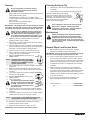
Grounding Instructions
This product must be grounded. In the event of an electrical
short circuit, grounding reduces the risk of electric shock by
providing an escape wire for the electric current. This product is
equipped with a cord having a grounding wire with an appropriate
grounding plug. The plug must be plugged into an outlet that
is properly installed and grounded in accordance with all local
codes and ordinances.
WARNING - Improper installation of the grounding plug can
result in a risk of electric shock.
If repair or replacement of the cord or plug is
necessary, do not connect the green grounding wire
to either at blade terminal. The wire with insulation
having a green outer surface with or without yellow
stripes is the grounding wire and must be connected
to the grounding pin.
Check with a qualied electrician or serviceman if the grounding
instructions are not completely understood, or if you are in doubt
as to whether the product is properly grounded. Do not modify
the plug provided. If the plug will not t the outlet, have the
proper outlet installed by a qualied electrician.
Grounded Outlet
Grounding Pin
Cover for grounded outlet box
IMPORTANT: Use only a 3-wire extension cord that has
a 3-blade grounding plug and a 3-slot receptacle that will
accept the plug on the product. Make sure your extension
cord is in good condition. When using an extension cord,
be sure to use one heavy enough to carry the current your
product will draw. An undersized cord will cause a drop in
line voltage resulting in loss of power and overheating. A 12
gauge cord is recommended. If an extension cord is to be
used outdoors, it must be marked with the suffix W-A after
the cord type designation. For example, a designation of
SJTW-A would indicate that the cord would be appropriate
for outdoor use.
Specications
Gallons per minute (GPM) ........ 0.60 (2.3 LPM)
Maximum tip sizes .................... 0.024”
Maximum pressure ................... 3100 PSI (21.4 MPa)
Power ....................................... 1.35 HP DCX motor, 120VAC
Weight (stand unit) ................... 33 lbs. (15 kg)
Maximum hose length .............. 300’ (91.4 m)

4 © SprayTECH. All rights reserved.
Table of Contents
Safety Precautions ................................................................... 2
Specications ........................................................................... 3
General Description ................................................................. 4
Operation ................................................................................... 4
Setup ................................................................................... 4
Preparing to Paint................................................................ 5
Painting ............................................................................... 5
Pressure Relief Procedure .................................................. 6
Spraying .................................................................................... 6
Spraying Technique ............................................................ 6
Practice ............................................................................... 6
Cleanup ..................................................................................... 7
Cleaning the Spray Tip ........................................................ 7
Maintenance .............................................................................. 7
General Repair and Service Notes...................................... 7
Replacing the PRIME/SPRAY Valve ................................... 8
Replacing the Filters............................................................ 8
Replacing the Motor Assembly............................................ 8
Replacing the Gears............................................................ 9
Replacing the Transducer ................................................. 10
Servicing the Fluid Section ................................................ 10
Troubleshooting ..................................................................... 12
Parts List ................................................................................. 18
Main Assembly .................................................................. 18
Motor Assembly................................................................. 19
Suction Set Assembly ....................................................... 19
Labels ................................................................................ 19
Gear Box Assembly........................................................... 20
Stand Assembly ................................................................ 21
Upright Cart Assembly ...................................................... 21
Fluid Section Assembly ..................................................... 22
Low Boy Cart Assembly .................................................... 23
Electrical Schematic............................................................... 23
Limited Warranty .................................................................... 24
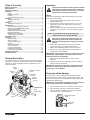
General Description
This airless sprayer is a precision power tool used for spraying
many types of materials. Read and follow this Owner’s Manual
carefully for proper operating instructions, maintenance, and
safety information.
Pressure Control
Knob
ON/OFF
Switch
PRIME/SPRAY
Valve
Outlet Fitting
Oil Cup
Siphon
Tube
Return
Hose
Filter
Circuit
Breaker
Operation
This equipment produces a fluid stream at extremely
high pressure. Read and understand the warnings
in the Safety Precautions section at the front of this
manual before operating this equipment.
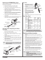
Setup
Perform the following procedure before plugging in the power
cord of an electric sprayer.
1. Ensure that the siphon tube and the return hose are
attached and secure.
2. Using a wrench, attach a minimum of 50’ of 1/4” nylon
airless spray hose to the outlet tting on the sprayer.
Tighten securely.
3. Attach an airless spray gun to the spray hose. Using two
wrenches (one on the gun and one on the hose), tighten
securely.
NOTE: Do not attach the tip to the spray gun yet.
Remove the tip if it is already attached.
Make sure all airless hoses and spray guns are
electrically grounded and rated at or above the
maximum operating pressure range of the airless
sprayer.
4. Make sure the pressure control knob is turned fully
counterclockwise to its lowest pressure setting.
5. Make sure the ON/OFF switch is in its OFF position.
6. Fill the oil cup with approximately one tablespoon of
separating oil (P/N 0279920).
IMPORTANT: Never operate unit for more than ten seconds
without fluid. Operating this unit without fluid will cause
unnecessary wear to the packings.
7. Make sure the electrical service is 120V, 15 amp
minimum.
8. Plug the power cord into a properly grounded outlet at
least 25’ from the spray area.
IMPORTANT: Always use a minimum 12 gauge, three-wire
extension cord with a grounded plug. Never remove the
third prong or use an adapter.
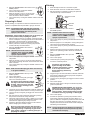
Preparing a New Sprayer
If this sprayer is new, it is shipped with test uid in the uid
section to prevent corrosion during shipment and storage. This
uid must be cleaned out of the system thoroughly with mineral
spirits before spraying paint.
IMPORTANT: Always keep the trigger lock on the spray gun
in the locked position while preparing the system.
1. Place the siphon tube into a container of mineral spirits.
2. Place the return hose into a metal waste container.
3. Set the pressure to minimum by turning the pressure
control knob fully counterclockwise.
Pressure Control
Knob
ON/OFF
Switch

© SprayTECH. All rights reserved. 5
4. Move the PRIME/SPRAY valve down to the
PRIME position.
5. Turn on the unit by moving the ON/OFF
switch to the ON position.
6. Allow the sprayer to run for 15–30 seconds
to ush the test uid out through the return
hose and into the waste container.
7. Turn off the unit by moving the ON/OFF switch to the OFF
position.
Preparing to Paint
Before painting, it is important to make sure that the uid in the
system is compatible with the paint that is going to be used.
NOTE: Incompatibleuidsandpaintmaycausethe
valves to become stuck closed, which would
require disassembly and cleaning of the
sprayer’suidsection.
IMPORTANT: Always keep the trigger lock on the spray gun
in the locked position while preparing the system.
1. Place the siphon tube into a container of the appropriate
solvent. Examples of the appropriate solvent are water for
latex paint or mineral spirits for oil-based paints.
2. Place the return hose into a metal waste container.
3. Set the pressure to minimum by turning the pressure
control knob fully counterclockwise.
4. Move the PRIME/SPRAY valve down to
the PRIME position.
NOTE: Hold the return hose in the waste
container when moving the PRIME/
SPRAY valve to PRIME in case the
sprayer is pressurized.
5. Turn on the sprayer by moving the ON/OFF switch to the
ON position.
6. Allow the sprayer to run for 15–30 seconds to ush the
old solvent out through the return hose and into the metal
waste container.
7. Turn off the sprayer by moving the ON/OFF switch to the
OFF position.
NOTE: Make sure that the spray gun does not have a tip
or tip guard installed.
8. Move the PRIME/SPRAY valve up to the
SPRAY position.
9. Turn on the sprayer.
10. Unlock the gun by turning the gun trigger
lock to the unlocked position.
Ground the gun by holding it against
the edge of the metal container while
flushing. Failure to do so may lead
to a static electric discharge, which
may cause a fire.
11. Trigger the gun into the metal waste container until the old
solvent is gone and fresh solvent is coming out of the gun.
12. Lock the gun by turning the gun trigger lock to the locked
position.
13. Set down the gun and increase the pressure by turning
the pressure control knob slowly clockwise.
14. Check the entire system for leaks. If leaks occur, turn the
unit off and follow the “Pressure Relief Procedure” in this
manual before tightening any ttings or hoses.
15. Follow the “Pressure Relief Procedure” in this manual
before changing from solvent to paint.
Be sure to follow the pressure relief procedure
when shutting down the sprayer for any purpose,
including servicing or adjusting any part of the
spray system, changing or cleaning spray tips, or
preparing for cleanup.
Painting
1. Place the siphon tube into a container of paint.
2. Place the return hose into a metal waste container.
3. Set the pressure to minimum by turning the pressure
control knob fully counterclockwise.
Pressure Control
Knob
ON/OFF
Switch
4. Move the PRIME/SPRAY valve down to
the PRIME position.
NOTE: Hold the return hose in the waste
container when moving the PRIME/
SPRAY valve to PRIME in case the
sprayer is pressurized.
5. Turn on the sprayer by moving the ON/OFF switch to the
ON position.
6. Allow the sprayer to run until paint is coming through the
return hose into the metal waste container.
7. Turn off the sprayer by moving the ON/OFF switch to the
OFF position.
8. Remove the return hose from the waste container and
place it in its operating position above the container of
paint.
9. Move the PRIME/SPRAY valve up to the
SPRAY position.
10. Turn on the sprayer.
11. Unlock the gun by turning the gun trigger
lock to the unlocked position.
Ground the gun by holding it
against the edge of the metal
container while flushing. Failure
to do so may lead to a static
electric discharge, which may
cause a fire.
12. Trigger the gun into the metal waste container until all air
and solvent is ushed from the spray hose and paint is
owing freely from the gun.
13. Lock the gun by turning the gun trigger lock to the locked
position.
14. Turn off the sprayer.
15. Attach tip guard and tip to the gun as instructed by the tip
guard or tip manuals.
POSSIBLE INJECTION HAZARD. Do not spray
without the tip guard in place. Never trigger the
gun unless the tip is in either the spray or the
unclog position. Always engage the gun trigger
lock before removing, replacing or cleaning tip.
16. Turn on the sprayer.
17. Increase the pressure by turning the pressure control
knob slowly clockwise and test the spray pattern on a
piece of cardboard. Adjust the pressure control knob until
the spray from the gun is completely atomized. Try to
keep the pressure control knob at the lowest setting that
maintains good atomization.
NOTE: Turning the pressure up higher then needed to
atomize the paint will cause premature tip wear
and additional overspray.

6 © SprayTECH. All rights reserved.
Pressure Relief Procedure
Be sure to follow the pressure relief procedure
when shutting the unit down for any purpose,
including servicing or adjusting any part of the
spray system, changing or cleaning spray tips, or
preparing for cleanup.
1. Lock the gun by turning the gun trigger lock to the locked
position.
2. Turn off the sprayer by moving the ON/OFF switch to the
OFF position.
3. Set the pressure to minimum by turning the pressure
control knob fully counterclockwise.
4. Unlock the gun by turning the gun
trigger lock to the unlocked position.
5. Hold the metal part of the gun rmly
to the side of a metal container to
ground the gun and avoid a build up
of static electricity.
6. Trigger the gun to remove any
pressure that may still be in the hose.
7. Lock the gun by turning the gun trigger
lock to the locked position.
8. Move the PRIME/SPRAY valve down to
the PRIME position.
Spraying
NOTE: Whensprayingblockller,masticsorhighsolid
coating,removethegunlterandhighpressure
lterscreens.
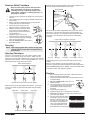
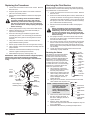
Spraying Technique
The key to a good paint job is an even coating over the entire
surface. This is done by using even strokes. Keep your arm
moving at a constant speed and keep the spray gun at a constant
distance from the surface. The best spraying distance is 10 to 12
inches between the spray tip and the surface.
Keep stroke smooth and at an even speed.
Even coat throughout
Approximately
10 to 12 inches
Keep the spray gun at right angles to the surface. This means
moving your entire arm back and forth rather than just exing
your wrist.
Heavy Coat
Do not flex wrist while spraying.
Light Coat Light Coat
Keep the spray gun perpendicular to the surface, otherwise one
end of the pattern will be thicker than the other.
Approximately
10 to 12 inches
Right way
Wrong way
The spray gun should be triggered by turning it on and off with
each stroke. This will save paint and avoid paint buildup at
the end of the stroke. Do not trigger the gun during the middle
of a stroke. This will result in an uneven spray and splotchy
coverage.
Proper way to trigger the spray gun
Approximately
10 to 12 inches
Keep stroke
even
Start stroke End strokePull trigger Release triggerKeep steady
Overlap each stroke by about 30%. This will ensure an even
coating.
When you stop painting, lock the gun trigger lock, turn the
pressure control knob counterclockwise to its lowest setting and
set the PRIME/SPRAY valve to PRIME. Turn the ON/OFF switch
to the OFF position and unplug the sprayer.
Practice
1. Be sure that the paint hose is free of kinks and clear of
objects with sharp cutting edges.
2. Turn the pressure control knob counterclockwise to its to
its lowest setting.
3. Move the PRIME/SPRAY valve up to its
SPRAY position.
4. Turn the pressure control knob clockwise
to its highest setting. The paint hose
should stiffen as paint begins to ow
through it.
5. Unlock the gun trigger lock.
6. Trigger the spray gun to bleed air out of the hose.
7. When paint reaches the spray tip, spray a test area to
check the spray pattern.
Good spray pattern
Paint tailing pattern
8. Use the lowest pressure setting
necessary to get a good spray
pattern. If the pressure is set
too high, the spray pattern will
be too light. If the pressure is
set too low, tailing will appear
or the paint will spatter out in
gobs rather than in a ne spray.

© SprayTECH. All rights reserved. 7
Cleanup
Do not use gasoline to clean the sprayer.
Special cleanup instructions for use with
flammable solvents:
• Always ush spray gun preferably outside and at least one
hose length from spray pump.
• If collecting ushed solvents in a one gallon metal
container, place it into an empty ve gallon container, then
ush solvents.
• Area must be free of ammable vapors.
• Follow all cleanup instructions.
IMPORTANT: The sprayer, hose, and gun should be cleaned
thoroughly after daily use. Failure to do so permits material
to build up, seriously affecting the performance of the unit.
Always spray at minimum pressure with the gun
nozzle tip removed when using mineral spirits or
any other solvent to clean the sprayer, hose, or
gun. Static electricity buildup may result in a fire
or explosion in the presence of flammable vapors.
1. Follow the “Pressure Relief Procedure” found in the
Operation section of this manual.
2. Remove the gun tip and tip guard and clean with a brush
using the appropriate solvent.
3. Place the siphon tube into a container of the appropriate
solvent. Examples of the appropriate solvent are water for
latex paint or mineral spirits for oil-based paints.
4. Place the return hose into a metal waste container.
5. Set the pressure to minimum by turning the pressure
control knob fully counterclockwise.
6. Move the PRIME/SPRAY valve down to its
PRIME position.
NOTE: Hold the return hose in the waste
container when moving the PRIME/
SPRAY valve to PRIME in case the
sprayer is pressurized.
7. Turn on the sprayer by moving the ON/OFF switch to the
ON position.
8. Allow the solvent to circulate through the sprayer and
ush the paint out of the return hose into the metal waste
container.
9. Turn off the sprayer by moving the ON/OFF
switch to the OFF position.
10. Move the PRIME/SPRAY valve up to its
SPRAY position.
11. Turn on the sprayer.
Ground the gun by holding it against
the edge of the metal container while
flushing. Failure to do so may lead
to a static electric discharge, which
may cause a fire.
12. Trigger the gun into the metal waste container until the
paint is ushed out of the hose and solvent is coming out
of the gun.
13. Continue to trigger the spray gun into the waste container
until the solvent coming out of the gun is clean.
NOTE: For long-term or cold weather storage, pump
mineral sprits through the entire system.
14. Follow the “Pressure Relief Procedure” found in the
Operation section of this manual.
15. Unplug the unit and store in a clean, dry area.
IMPORTANT: Do not store the unit under pressure.
Cleaning the Spray Tip
1. Flush the gun with solvent immediately after the work is
completed.
2. Oil the retractor pins to prevent them from seizing up.
Should the spray tip become clogged,
reverse the spray tip with the lever and pull
the trigger. Once the obstruction comes out
of the spray tip, release the trigger, reverse
the spray tip back to the spray pattern
setting, and resume spraying.
Do not attempt to clean the tip with your finger.
Do not use a needle or other sharp pointed
instrument to clean the tip. The hard tungsten
carbide is brittle and can be chipped.
Maintenance
Before proceeding, follow the Pressure Relief
Procedure outlined previously in this manual.
Additionally, follow all other warnings to reduce
the risk of an injection injury, injury from moving
parts or electric shock. Always unplug the sprayer
before servicing!
General Repair and Service Notes
1. Before repairing any part of the sprayer, read the
instructions carefully, including all warnings.
IMPORTANT: Never pull on a wire to disconnect it. Pulling
on a wire could loosen the connector from the wire.
2. Test your repair before regular operation of the sprayer
to be sure that the problem is corrected. If the sprayer
does not operate properly, review the repair procedure to
determine if everything was done correctly. Refer to the
Troubleshooting section to help identify other possible
problems.
3. Make sure that the service area is well ventilated in
case solvents are used during cleaning. Always wear
protective eyewear while servicing. Additional protective
equipment may be required depending on the type of
cleaning solvent. Always contact the supplier of solvents
for recommendations.
4. If you have any further questions concerning your
SprayTECH Airless Sprayer, call SprayTECH:
Technical Service .................................. 1-800-292-4637
Fax ................................................ 1-800-525-9501

8 © SprayTECH. All rights reserved.
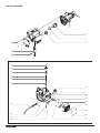
Replacing the PRIME/SPRAY Valve
Perform the following procedure using PRIME/SPRAY valve
replacement kit P/N 0507690.
1. Drive the groove pin out of the valve handle.
2. Remove the valve handle and the cam base.
3. Using a wrench, loosen and remove the valve housing
assembly from the pump manifold.
4. Make sure the gasket is in place and thread the new
valve housing assembly into the pump manifold. Tighten
securely with a wrench.
5. Place the cam base over the valve housing assembly.
Lubricate the cam base with grease and line up the cam
with the pump manifold using the dowel pin.
6. Line up the hole on the valve stem with the hole in the
valve handle.
7. Insert the groove pin into the valve handle and through the
valve stem to secure the valve handle in position.
Dowel Pin
Groove Pin
Valve Stem
Gasket
Pump
Manifold
Valve Housing
Assembly
Valve
Handle
Cam Base
Cleaning and/or Replacing the Filters
Pump Filter
1. Loosen and remove the lter housing by hand. Pull the
lter out of the pump manifold.
2. Slip the lter off of the lter support spring.
3. Inspect the lter. Based on inspection, clean or replace
the lter.
4. Inspect the lter seal. Based on inspection, clean or
replace the lter seal.
5. Slide the new or cleaned lter over the lter support spring
with the adapter in place. Push the lter into the center of
the pump manifold.
6. Slide the lter housing over the lter and thread it into the
pump manifold until secure.
NOTE: Thelterhousingshouldbehand-tightened,but
makesurethelterhousingisseatedfullyinto
the pump manifold.
Filter
Spring
Adapter
Filter Support Spring
Filter Seal
Pump Manifold
Filter
Filter
Housing
Gun Filter
Gun
Housing
Filter
Handle
Handle
Seal
1. Pull the bottom of the trigger
guard forward so that it
comes loose from the handle
assembly.
2. Loosen and remove the handle
assembly from the gun head.
3. Pull the old lter out of the gun
head.
4. Slide the new lter, tapered
end rst, into the gun head.
5. Make sure the handle seal is in
position and thread the handle
assembly into the gun head
until secure.
6. Snap the trigger guard back onto the handle assembly.
Gun Filter Chart
Part
Number
Application Filter
Type
Color of
Filter
Body
0089960 Synthetic resin,
enamels, clean
varnishes, stains
azures
Extrafine red
0089959 Base coat enamels,
primer enamels,
fillers, marking paints,
textured enamels
Fine yellow
0089958 Emulsions,
latex paints,
acrylic paints
Medium white
0089957 Heavy bodied latex,
blockfillers,
elastometrics
Coarse green
NOTE: For more detail, part number information, and
an assembly drawing, please see the G-10 XL
Airless Spray Gun Owner’s Manual (P/N 0296237).
Replacing the Motor Assembly
1. Perform the Pressure Relief Procedure and unplug the
sprayer.
2. Remove the four motor cover screws. Remove the motor
cover.
3. Remove the four heat sink assembly screws. Pull the heat
sink assembly away from the gear box housing.
4. Disconnect the ve wires from the relay that is mounted
on the inside of the heat sink assembly.
5. Remove the three relay mounting screws from the heat
sink assembly. Remove the relay.
6. Using the three relay mounting screws, install the new relay
onto the heat sink assembly. Tighten the screws securely.
7. Connect the ve wires to the new relay (refer to the
electrical schematic in the Parts List section of this manual).
8. Using the four heat sink assembly screws, install the heat
sink assembly onto the gear box housing. Tighten the
screws securely.
9. Disconnect the black and red wires coming from the gear
box housing. Disconnect the black and red wires from the
capacitors. Disconnect the black and red wires from the motor.
10. Loosen and remove the four motor mounting screws.
11. Pull the motor out of the gear box housing.
NOTE: If the motor will not dislodge from the pump
housing:
•Removethefrontcoverplate.
•Usingarubbermallet,carefullytaponthefront
of the motor crankshaft that extends through
the slider assembly.

© SprayTECH. All rights reserved. 9
12. With the motor removed, inspect the gears in the gear
box housing for damage or excessive wear. Replace the
gears, if necessary.
13. Install the new motor into the gear box housing.
NOTE: Rotate the motor fan manually until the armature
gear engages with the mating gear in the gear
box housing.
14. Secure the motor with the four motor mounting screws.
15. Push the new capacitors into their clip on the new motor.
16. Reconnect the wires (refer to the electrical schematic in
the Parts List section of this manual).
17. Slide the motor cover over the motor. Secure the motor
cover with the four motor cover screws.
Motor
Cover
Screw
Heat Sink
Assembly Screw
Heat Sink
Assembly
Fan
Shroud
Screw
Fan
Shroud
Brush
Cover
Relay
Relay Mounting
Screw
Motor
Motor
Mounting
Screw
Gear Box
Housing
Capacitors
Motor Cover
BLACK
BLACK
RED
BLACK
RED
RED
Replacing the Motor Brushes
Perform this procedure using Motor Brush Kit P/N 0508645.
1. Perform the Pressure Relief Procedure and unplug the
sprayer.
2. Loosen and remove the four motor cover screws.
Remove the motor cover.
3. Loosen and remove the two fan shroud screws. Remove
the fan shroud.
4. Using a small screwdriver, pry off the two plastic brush
covers.
5. Disconnect the black and red wires from the motor
brushes. Remove the motor brushes.
6. Install the new motor brushes and snap on the plastic
brush covers.
7. Reconnect the black and red wires from the motor brushes
(refer to the electrical schematic in the Parts List section of
this manual).
8. Position the fan shroud over the motor fan. Secure the
fan shroud with the two fan shroud screws.
9. Slide the motor cover over the motor. Secure the motor
cover with the four motor cover screws.
Replacing the Gears
1. Perform the Pressure Relief Procedure and unplug the
sprayer.
2. Loosen and remove the four motor cover screws.
Remove the motor cover.
3. Disconnect the black and red wires coming from the gear
box housing.
4. Loosen and remove the four motor mounting screws.
5. Pull the motor out of the gear box housing.
NOTE: If the motor will not dislodge from the pump
housing:
•Removethefrontcoverplate.
•Usingarubbermallet,carefullytaponthefront
of the motor crankshaft that extends through
the slider assembly.
6. Inspect the armature gear on the end of the motor for
damage or excessive wear. If this gear is completely worn
out, replace the entire motor.
7. Remove and inspect the 2nd stage gear for damage or
excessive wear. Replace if necessary.
8. Remove and inspect the crankshaft/gear assembly for
damage or excessive wear. Replace if necessary.
9. Reassemble the pump by reversing the above steps.
During reassembly, make sure the thrust washers is in
place.
NOTE: RellthegearboxwithveouncesofLubriplate
(P/N 9870307).
Front Cover
Gear Box Housing
Front Cover Screw
2nd Stage Gear
Thrust Washer
Motor Mounting
Screw
Crankshaft/Gear
Assembly
Armature Gear
Motor
Motor Cover
Motor Cover Screw

10 © SprayTECH. All rights reserved.
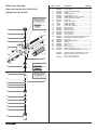
Replacing the Transducer
1. Loosen and remove the four front cover screws. Remove
the front cover.
2. Stop the sprayer at the bottom of its stroke so that the
piston is in its lowest position.
3. Perform the Pressure Relief Procedure and unplug the
sprayer.
Before proceeding, follow the Pressure Relief
Procedure outlined previously in this manual.
Additionally, follow all other warnings to reduce
the risk of an injection injury, injury from moving
parts or electric shock. Always unplug the sprayer
before servicing!
4. Tilt the sprayer back for easy access to the uid section.
5. Slide the retaining ring up on the slider assembly to
expose the connecting pin.
6. Push the connecting pin forward through the slider
assembly and piston. The connecting pin will fall into a
recessed area of the gear box housing where it can be
retrieved.
7. Using 3/8” a hex wrench, loosen and remove the two
pump manifold mounting screws.
8. Pull the pump manifold down off of the gear box housing.
9. Using a wrench, remove the transducer assembly from the
pump manifold.
10. Thread the new transducer assembly into the pump
manifold. Tighten securely with a wrench.
11. Reassemble the pump by reversing steps 1–8.
IMPORTANT: Make sure the transducer is aligned properly
with the hole in the pump block during reassembly.
Improper alignment may cause damage to the transducer
o-ring.
Gear Box
Housing
Slider
Assembly
Pump
Manifold
Pump
Manifold
Mounting
Screw
Front
Cover
Front
Cover
Screw
Transducer
Assembly
Connecting Pin
Retaining Ring
Servicing the Fluid Section
Use the following procedures to service the valves and repack
the uid section. Perform the following steps before performing
any maintenance on the uid section.
1. Loosen and remove the four front cover screws. Remove
the front cover.
2. Position the slider assembly at the bottom, dead-center of
its stroke so that the connecting pin and retaining ring are
visible below the slider assembly. This is done by turning
the sprayer on and off in short bursts until the connecting
pin is visible below the slider housing.
3. Perform the Pressure Relief Procedure and unplug the
sprayer.
Before proceeding, follow the Pressure Relief
Procedure outlined previously in this manual.
Additionally, follow all other warnings to reduce
the risk of an injection injury, injury from moving
parts or electric shock. Always unplug the sprayer
before servicing!
4. For Upright Cart units, remove the return hose from the
hose clip on the siphon tube. Unscrew the siphon tube
from the inlet valve housing.
5. For Low Boy cart units, remove the retaining ring from the
bottom of the inlet valve housing using a snap ring pliers.
Remove the return hose clamp and pull the return hose
from its tting on the pump manifold. Remove the suction
set assembly.
6. Loosen and remove the high-pressure hose from the
outlet tting on pump manifold.
Inlet Valve
Housing
PTFE
O-Ring
Inlet Valve
Seat
Inlet Valve
Ball
Inlet Valve
Cage
Nylon
Washer
Piston
Bushing
Pump
Manifold
Servicing the Valves
The design of the uid section allows
access to the inlet valve and seat
as well as the outlet valve and seat
without completely disassembling the
uid section. It is possible that the
valves may not seat properly because
of debris stuck in the foot valve seat
or outlet valve seat. Use the following
instructions to clean the valves and
reverse or replace the seats.
1. Using a wrench, loosen and
remove the inlet valve housing
from the pump manifold.
2. Clean out any debris in the inlet
valve housing and examine the
valve housing and seat. If the
seat is damaged, reverse or
replace the seat.
3. Using a 5/16” hex wrench, loosen and remove the outlet
valve retainer from the piston rod.
Outlet Valve
Retainer
Outlet Valve
Seat
Outlet Valve
Ball
Outlet Valve
Cage
Piston Rod
NOTE: Always service the outlet
valve with the piston rod
attached to the pump.
This will prevent the
piston rod from rotating
during disassembly of the
outlet valve.
4. Clean out any debris and examine
the valve housing and seat. If
the seat is damaged, reverse or
replace the seat.
5. Remove, clean, and inspect the
outlet valve cage and outlet valve ball. Replace if they are
worn or damaged.
6. Reassemble the valves by reversing the steps above.

© SprayTECH. All rights reserved. 11
Repacking the Fluid Section
1. Remove the inlet valve assembly using the steps in the
“Servicing the Valves” procedure above.
NOTE: The outlet valve does not need to be
disassembled from the piston rod for this
procedure.
Slider Assembly
Connecting Pin
Retaining Ring
Retainer Nut
Piston Guide
Upper Packing
Assembly
Pump Manifold
Pump Manifold
Mounting Screw
Piston Rod
Lower Packing
Assembly
Spacer
2. Slide the retaining
ring up on the slider
assembly to expose
the connecting pin.
3. Push the connecting
pin forward through
the slider assembly
and piston. The
connecting pin will
fall into a recessed
area of the gear box
housing where it can
be retrieved.
4. Using 3/8” a hex
wrench, loosen and
remove the two pump
manifold mounting
screws.
5. Pull the pump
manifold down off of
the gear box housing.
6. Slide the piston
rod out through the
bottom of the pump
manifold.
7. Loosen and remove
the retainer nut and
piston guide from the
pump manifold.
8. Remove the upper
and lower packings
from the pump manifold.
9. Clean the pump manifold and install the new upper and
lower packings. Refer to the illustration below for proper
packing orientation.
Install lower packings
with raised lip and O-ring
facing up.
Install upper packing
with raised lip and O-ring
facing down.
O-Ring
O-Ring
Raised Lip
Raised Lip
10. Inspect the piston rod for wear and replace if necessary.
11. Insert the piston guide into the retainer nut. Thread the
retainer nut into the pump manifold until it is hand tight.
12. Slide the piston guide tool (included in the repacking kit)
over the top of the piston rod and insert the piston rod
through the bottom of the pump manifold. Using a rubber
mallet, tap the bottom of the piston rod lightly until the
piston rod is in position in the pump manifold.
NOTE: Coat the piston guide tool and the piston rod
with grease before inserting them into the pump
manifold.
13. Using a wrench, tighten the retainer nut securely.
14. Position the pump block underneath the pump housing
and push up until it rests against the pump housing.
When the connecting pin hole on the piston rod lines up
with the hole in the slider assembly, insert the connecting
pin.
15. Slide the retaining ring down over the connecting pin.
IMPORTANT: Make sure the transducer is aligned properly
with the hole in the pump manifold during reassembly.
Improper alignment may cause damage to the transducer
gasket.
16. Thread the pump manifold mounting screws through the
pump manifold and into the gear box housing. Tighten
securely.
17. Reassemble the inlet valve assembly into the pump
manifold.
18. For Upright Cart units, thread the siphon tube into the inlet
valve and tighten securely. Make sure to wrap the threads
on the down tube with PTFE tape before assembly. Replace
the return hose into the hose clip on the siphon tube.
19. For Low Boy cart units, insert the elbow on the suction set
assembly into the bottom of the inlet valve housing. Push
the retaining ring up into the groove inside the inlet valve
housing to secure the suction set assembly in position. Push
the return hose onto the return hose tting on the pump
manifold and secure in position with the return hose clamp.
20. Place the front cover on the gear box housing and secure
in position using the four front cover screws.
21. Turn on the sprayer by following the procedure in the
“Operation” section of this manual and check for leaks.
NOTE: Repacking kit P/N 0551533 is available. For best
results use all parts supplied in this kit.

12 © Titan Tool Inc. All rights reserved.
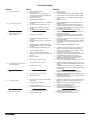
Problem
A. The unit will not run.
B. The unit will not prime.
C. The unit will not build or
maintain pressure.
D. Fluid leakage at the upper end
of the uid section.
E. Excessive surge at the spray
gun.
F. Poor spray pattern.
G. The unit lacks power.
Cause
1. The unit is not plugged in.
2. Tripped breaker.
3. The pressure is set too low (pressure
control knob set at minimum setting does
not supply power to unit).
4. Faulty or loose wiring.
5. Excessive motor temperature.
1. The PRIME/SPRAY valve is in the SPRAY
position.
2. Air leak in the siphon tube/suction set.
3. The pump lter and/or inlet screen is
clogged.
4. The siphon tube/suction set is clogged.
1. The spray tip is worn.
2. The spray tip is too large.
3. The pressure control knob is not set
properly.
4. The pump lter, gun lter, or inlet screen is
clogged.
5. Material ows from the return hose when
the PRIME/SPRAY valve is in the SPRAY
position.
6. Air leak in the siphon tube/suction set.
7. There is external uid leak.
8. There is an internal uid section leak
(packings are worn and/or dirty, valve balls
are worn).
9. Worn valve seats
10. Motor powers but fails to rotate
1. The upper packings are worn.
2. The piston rod is worn.
1. Wrong type of airless spray hose.
2. The spray tip worn or too large.
3. Excessive pressure.
1. The spray tip is too large for the material
being used.
2. Incorrect pressure setting.
3. Insufcient uid delivery.
4. The material being sprayed is too viscous.
1. The pressure adjustment is too low.
2. Improper voltage supply.
Solution
1. Plug the unit in.
2. Reset the breaker.
3. Turn the pressure control knob clockwise to supply
power to the unit and increase the pressure setting.
4. Inspect or take to a SprayTECH authorized service
center.
5. Allow motor to cool.
1. Rotate the PRIME/SPRAY valve clockwise to the
PRIME position.
2. Check the siphon tube/suction set connection and
tighten or re-tape the connection with PTFE tape.
3. Remove the pump lter element and clean. Remove
the inlet screen and clean.
4. Remove the siphon tube/suction set and clean.
1. Replace the spray tip following the instructions that
came with the spray gun.
2. Replace the spray tip with a tip that has a smaller
orice following the instructions that came with the
spray gun.
3. Turn the pressure control knob clockwise to increase
the pressure setting.
4. Remove the pump lter element and clean. Remove
the gun lter and clean. Remove the inlet screen
and clean.
5. Clean or replace the PRIME/SPRAY valve.
6. Check the siphon tube/suction set connection and
tighten or re-tape the connection with PTFE tape.
7. Check for external leaks at all connections. Tighten
connections, if necessary.
8. Clean the valves and service the uid section
following the “Servicing the Fluid Section” procedure
in the Maintenance section of this manual.
9. Reverse or replace the valve seats following the
“Servicing the Fluid Section” procedure in the
Maintenance section of this manual.
10. Take unit to a SprayTECH authorized service center.
1. Repack the pump following the “Servicing the Fluid
Section” procedure in the Maintenance section of this
manual.
2. Replace the piston rod following the “Servicing the
Fluid Section” procedure in the Maintenance section
of this manual.
1. Replace hose with a minimum of 50’ of 1/4”
grounded textile braid airless paint spray hose.
2. Replace the spray tip following the instructions that
came with the spray gun.
3. Rotate the pressure control knob counterclockwise to
decrease spray pressure.
1. Replace the spray tip with a new or smaller spray tip
following the instructions that came with the spray
gun.
2. Rotate the pressure control knob to adjust the
pressure for a proper spray pattern.
3. Clean all screens and lters.
4. Add solvent to the material according to the
manufacturer’s recommendations.
1. Rotate the pressure control knob clockwise to
increase the pressure setting.
2. Reconnect the input voltage for 120V AC.
Troubleshooting

© Titan Tool Inc. All rights reserved. 13
Notes
Page is loading ...
Page is loading ...
Page is loading ...
Page is loading ...

Parts List
Main Assembly
1
3
4
5
20
2
18
19
17
16
13
14
6
7
8
9
10
11
12
15
Item Part # Description Quantity
1 0552300 Motor cover ...............................................1
2 0551440 Screw ........................................................4
3 9800308 Screw ........................................................4
4 ---------- Motor assembly ........................................1
5 0551526 Left leg assembly (stand only) ..................1
6 0551443 Pail hook (upright cart only)
7 0508549 Washer (upright cart only) ........................2
8 0508550 Screw (upright cart only) ...........................2
9 0507783 Hose clip (upright cart only) ......................1
10 0551556 Return hose (upright cart only) .................1
11 0508552 Siphon tube (upright cart only) .................1
12 5006536 Inlet screen (upright cart only) .................1
13 ---------- Gear box assembly...................................1
Item Part # Description Quantity
14 0509550 Screw (stand) ...........................................4
0509244 Screw (upright cart)
0508590 Screw (low boy)
15 0551524 Right leg assembly (stand only) ...............1
16 0509636 Plug ..........................................................2
17 0551603 Fluid section assembly
(stand and low boy cart) ...........................1
0551602 Fluid section assembly (upright cart)
18 0508553 Screw ........................................................2
19 805-257 Suction set assembly
(stand and low boy cart) ...........................1
20 9885612 Return tube tting .....................................1
21 0327226 Return hose clamp (not shown)................1
18 © SprayTECH. All rights reserved.

Motor Assembly
3
2
4
5
6
7
1
Item Part # Description Quantity
1 0551215 Motor assembly (includes items 2–7) .......1
2 0551543 Tie wrap ....................................................2
3 0551514 Capacitor ..................................................1
4 0508646 Fan shroud ...............................................2
5 9802891 Screw ........................................................2
Item Part # Description Quantity
6 0508648 Fan ...........................................................1
7 9804916 Fan screw .................................................1
8 0508653 Double-sided tape (not shown).................1
0508645 Motor Brush Kit
© SprayTECH. All rights reserved. 19
NOTE: All electrical work should be performed by an
SprayTECH authorized service center.
Suction Set Assembly (P/N 805-257)
1
2
3
4
Item Part # Description Quantity
1 805-258 Siphon tube assembly ..............................1
2 805-259 Return hose assembly ..............................1
3 0279459 Hose clip ...................................................1
4 9850638 Tie wrap ....................................................2
Labels
Part # Description
0552703 Logo label, front
0552704 Logo label, left
0552704 Logo label, right
0551485 Warning label, explosion/injection
0295805 Shock hazard label
0507856 PRIME/SPRAY label

Gear Box Assembly
1
2
3
4
5
9
10
11
12
13
14
15
16
17
18
6
7
8
19
18
20
21
22
23
25
24
26
27
20 © SprayTECH. All rights reserved.

Item Part # Description Quantity
1 0509218 Screw ........................................................4
2 0552314 Front cover ...............................................1
3 0551541 Slider assembly ........................................1
4 0507777 Connecting pin..........................................1
5 0507768 Retaining ring ...........................................1
6 0508572 Crankshaft/gear assembly ........................1
7 0508573 Thrust washer ...........................................1
8 0509121 Second stage gear ...................................1
9 0509219 Screw ........................................................1
10 0551513 Pressure control knob...............................1
11 0551522 Knob housing............................................1
12 02712 Knob spring ..............................................1
13 9822522 Washer .....................................................1
14 0551521 Plunger .....................................................1
15 800-741 Power cord assembly (stand) ...................1
806-213 Power cord assembly
(low boy and upright cart)
Item Part # Description Quantity
16 9800340 Ground screw ...........................................1
17 0551112 Transducer assembly (includes o-ring) ....1
18 0551515 Circuit breaker ..........................................1
19 9850936 ON/OFF switch .........................................1
20 03662 Microswitch insulator ................................1
21 0295490 Microswitch ...............................................1
22 9800604 Screw ........................................................2
23 9852334 Relay, 120V ..............................................1
24 0507751 Port plug ...................................................1
25 0509218 Screw ........................................................4
26 0522214 Heat sink assembly
(includes items 24 and 25) .......................1
27 0551495 Screw ........................................................3
0551520 Mechanical control assembly
(includes items 11–14)
Stand Assembly
2
1
3
5
4
6
7
8
10
9
Item Part # Description Quantity
1 0508377 Cord wrap .................................................1
2 0551525 Plug ..........................................................4
3 0551526 Left leg assembly
(includes items 1, 2, and 7) ......................1
4 0551483 Clip assembly ...........................................1
5 0551484 Screw ........................................................1
6 0508381 Drip cup ....................................................1
7 0551527 Screw ........................................................2
8 0509856 Nut ............................................................1
9 0551524 Right leg assembly
(includes items 2, 4, 5, 6, 8, and 10)
10 0507955 Screw ........................................................1
Upright Cart Assembly
1
2
3
4
5
7
10
11
12
10
14
15
13
7
8
9
6
Item Part # Description Quantity
1 0551664 Handle assembly
(includes items 2–5, 10 and 11.................1
2 0295607 Handle sleeve ...........................................2
3 9841504 Snap button ..............................................2
4 0295609 Handle washer..........................................2
5 0295610 Roll pin ......................................................2
6 9890104 Cap ...........................................................2
7 0294534 Spacer ......................................................4
8 0551550 Plug ..........................................................2
9 0551548 Plug ..........................................................2
10 0295606 Washer .....................................................6
11 0295608 Screw ........................................................4
12 0507655 Cord wrap .................................................2
13 0551555 Screw ........................................................4
14 0551665 Cart weldment (includes items 8 and 9) ...1
15 0278373 Wheel .......................................................2
© SprayTECH. All rights reserved. 21

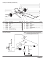
Fluid Section Assembly
(Stand and Low Boy Cart P/N 0551603)
(Upright Cart P/N 0551602)
1
7
8
9
10
11
12
13
14
15
16
17
18
19
20
2
3
4
5
6
24
21
22
23
25
26
27
28
Install lower packings
with raised lip and
O-ring facing up.
O-Ring
Raised Lip
Install upper packing
with raised lip and
O-ring facing down.
O-Ring
Raised Lip
Item Part # Description Quantity
1 0508664 Retainer nut ..............................................1
2 0508665 Piston guide ..............................................1
3 0551538 Upper packing assembly ..........................1
4 0551535 Spacer ......................................................1
5 0551604 Pump manifold..........................................1
6 0509873 Outlet tting, 1/4” ......................................1
7 0507690 PRIME/SPRAY valve assembly ..............1
8 0551539 Lower packing assembly ..........................2
9 0551537 Piston rod .................................................1
10 0295307 Outlet valve cage ......................................1
11 50164 Outlet valve ball ........................................1
12 13359 Outlet valve seat .......................................1
13 13481 Outlet valve retainer .................................1
14 0508676 Piston bushing ..........................................1
15 0508739 Nylon washer ............................................1
16 0508677 Inlet valve cage.........................................1
17 0508678 Inlet valve ball ...........................................1
18 0551534 Inlet valve seat..........................................1
19 0509582 O-ring, PTFE ............................................1
20 0508680
Inlet valve housing (stand and low boy cart)
..1
0508690 Inlet valve housing (upright cart)
21 0508604 Filter seal ..................................................1
22 0508749 Filter support spring ..................................1
23 0508603 Adapter .....................................................1
24 0508602 Filter spring ...............................................1
25 0508748 Filter ..........................................................1
26 0508601 Filter housing ............................................1
27 0551530 Return hose ttiing, 1/8” ...........................1
28 0551536 Piston assembly (includes items 9–13) ....1
0551605 Filter assembly (includes items 21–26) ....1
0551533 Repacking kit (includes items 2–4, 8
10–11, 15, 17, and 19)
0551509 Lower seal insertion too
22 © SprayTECH. All rights reserved.

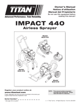
Low Boy Cart Assembly (P/N 0555147)
9
10
11
12
13
14
15
16
17
18
20
19
1
2
3
4
6
7
8
3
5
Item Part # Description Quantity
1 0551608 Cart weldment (includes items 6 and 14) .1
2 0507956 Roll pin ......................................................2
3 0294534 Wheel spacer ............................................4
4 0270394 Wheel .......................................................2
5 9890104 Cap ...........................................................2
6 0551548 Plug ..........................................................2
7 0295615 Lock nut ....................................................2
8 0507955 Screw ........................................................1
9 0295618 Screw ........................................................2
10 0551551 Mounting bracket, left ...............................1
11 0551552 Mounting bracket, right .............................1
Item Part # Description Quantity
12 0295608 Screw ........................................................4
13 0295606 Washer .....................................................4
14 0551525 Plug ..........................................................2
15 0295609 Handle washer..........................................2
16 0295610 Roll pin ......................................................2
17 9841504 Snap button ..............................................2
18 0295607 Sleeve .......................................................2
19 0551609 Handle asssembly
(includes items 12, 13, and 15–18............1
20 0508381 Drip cup ....................................................1
Electrical Schematic
BLACK
BLACK
RED
RED
Motor
Plug
+
–
+
–
Capacitors
BROWN
BROWN
BLACK
BLACK
BLUE
GREEN
WHITE
WHITE
Switch
1
2
3
4
Load
Line
Circuit
Breaker
Microswitch
704-269
Relay
Black “Y” Adapter Wire
Red “Y” Adapter Wire
NOTE: All electrical work should be performed by an
SprayTECH authorized service center.
© SprayTECH. All rights reserved. 23

Limited Warranty
SprayTECH Corporation, (“SprayTECH”) warrants that at the time of delivery to the original purchaser for use (“End User”), the
equipment covered by this warranty is free from defects in material and workmanship. With the exception of any special, limited, or
extended warranty published by SprayTECH, SprayTECH’s obligation under this warranty is limited to replacing or repairing without
charge those parts which, to SprayTECH’s reasonable satisfaction, are shown to be defective within twelve (12) months after sale to the
End User. This warranty applies only when the unit is installed and operated in accordance with the recommendations and instructions
of SprayTECH.
This warranty does not apply in the case of damage or wear caused by abrasion, corrosion or misuse, negligence, accident, faulty
installation, substitution of non-SprayTECH component parts, or tampering with the unit in a manner to impair normal operation.
Defective parts are to be returned to an authorized SprayTECH sales/service outlet. All transportation charges, including return to the
factory, if necessary, are to be borne and prepaid by the End User. Repaired or replaced equipment will be returned to the End User
transportation prepaid.
THERE IS NO OTHER EXPRESS WARRANTY. SPRAYTECH HEREBY DISCLAIMS ANY AND ALL IMPLIED WARRANTIES
INCLUDING, BUT NOT LIMITED TO, THOSE OF MERCHANTABILITY AND FITNESS FOR A PARTICULAR PURPOSE, TO THE
EXTENT PERMITTED BY LAW. THE DURATION OF ANY IMPLIED WARRANTIES WHICH CANNOT BE DISCLAIMED IS LIMITED
TO THE TIME PERIOD SPECIFIED IN THE EXPRESS WARRANTY. IN NO CASE SHALL SPRAYTECH LIABILITY EXCEED THE
AMOUNT OF THE PURCHASE PRICE. LIABILITY FOR CONSEQUENTIAL, INCIDENTAL OR SPECIAL DAMAGES UNDER ANY
AND ALL WARRANTIES IS EXCLUDED TO THE EXTENT PERMITTED BY LAW.
SPRAYTECH MAKES NO WARRANTY AND DISCLAIMS ALL IMPLIED WARRANTIES OF MERCHANTABILITY AND FITNESS
FOR A PARTICULAR PURPOSE WITH RESPECT TO ACCESSORIES, EQUIPMENT, MATERIALS OR COMPONENTS SOLD BUT
NOT MANUFACTURED BY SPRAYTECH. THOSE ITEMS SOLD, BUT NOT MANUFACTURED BY SPRAYTECH (SUCH AS GAS
ENGINES, SWITCHES, HOSES, ETC.) ARE SUBJECT TO THE WARRANTY, IF ANY, OF THEIR MANUFACTURER. SPRAYTECH
WILL PROVIDE THE PURCHASER WITH REASONABLE ASSISTANCE IN MAKING ANY CLAIM FOR BREACH OF THESE
WARRANTIES.
Patents
These products are covered by one or more of the following U.S. patents:
6,031,352 5,848,566 5,769,321 5,725,364 5,671,656 5,435,697 5,228,842
5,346,037 5,252,210 5,217,238 5,192,425 4,908,538 4,768,929 4,744,571
D384,676 6,179,222 5,934,883 4,723,892
Material Safety Data Sheets (MSDS) are available on Titan’s website or by calling Customer Service.
24 © SprayTECH. All rights reserved.
SprayTECH
1770 Fernbrook Lane
Minneapolis, MN 55447
Technical Assistance/
Order Entry:
Fax - Technical Assistance:
Fax - Order Entry:
1-800-526-5362
1-800-525-9501
1-800-528-4826
www.spraytechinc.com
-
 1
1
-
 2
2
-
 3
3
-
 4
4
-
 5
5
-
 6
6
-
 7
7
-
 8
8
-
 9
9
-
 10
10
-
 11
11
-
 12
12
-
 13
13
-
 14
14
-
 15
15
-
 16
16
-
 17
17
-
 18
18
-
 19
19
-
 20
20
-
 21
21
-
 22
22
-
 23
23
-
 24
24


Titan Advantage EXP2255 Owner's manual
- Category
- Paint Sprayer
- Type
- Owner's manual
- This manual is also suitable for
Ask a question and I''ll find the answer in the document
Finding information in a document is now easier with AI
Related papers
-
Titan EPX2555 Owner's manual
-
-
-
-
-
-
-
-
-
Other documents
-
 Dino-Power Titan 440i Owner's manual
-
Cusco 1A9-820-F User manual
-
WAGNER 295001 User manual
-
-
 Wagner SprayTech 1920 User manual
-
-
-
-
-
WAGNER 0558022 Owner's manual

