Page is loading ...

YSI i n c o r p o r a t e d
YSI MODEL 6500
Environmental Process Monitor
Operations Manual


CONTENTS
Page
Section 1 INTRODUCTION 1
1.1 6500 Monitor Features 1
1.2 How to Use This Manual 2
Section 2 INSTALLATION 3
2.1 Unpacking and Inspection 3
2.2 Selecting an Installation Location 3
2.3 Installing the Sonde 7
2.4 Installing the 6500 Monitor 9
2.5 Wiring Instructions 11
2.5.1 Sonde Connections 11
2.5.2 AC Power Connections 13
2.5.3 Relays and Output Wiring 14
2.5.4 Grounding Information 15
2.5.5 Safety Issues 15
2.5.6 Lightning and Surge Protection 15
2.6 Sealants, Desiccant and Securing the Monitor 16
2.7 Installation Check List 17
Section 3 SYSTEM SETUP 19
3.1 System Configuration 19
3.2 6-Series Sonde Setup 20
3.3 6500 Monitor Setup 23
3.3.1 Calibration setup 24
3.3.2 Display setup 26
3.3.3 Relays 29
3.3.4 4-20 mA channel setup 31
3.3.5 Modbus Setup 32
3.3.6 Change Sonde Address 33
3.3.7 System Status 35
Section 4 CALIBRATION 37
4.1 General Calibration Tips 37
4.2 Field Calibration Using the 6500 Monitor 40
4.3 6500 calibration Warning and Error Messages 42
Section 5 PROPER USE AND CARE OF THE 6500 MONITOR SYSTEM 43
5.1 Deciding How to Use Your Monitoring System 43
5.2 Quality Assurance 47
5.2.1 Sonde Maintenance and Deployment Site 48
5.2.2 Calibration Checks 49
5.2.3 Recommended Quality Assurance Protocol 49
5.2.4 Recommended Monthly Maintenance of DO Probe 51
5.2.5 Recommended Cleaning of the 6500 Enclosure 52
i

Section 6 TROUBLESHOOTING 53
6.1 Communication Problems 53
6.2 6500 Menu Choice Problems 55
6.3 Calibration Error Messages 56
6.4 Sensor Accuracy and Repeatability Problems 56
6.5 Alarm Function Problems 57
6.6 4-20 mA Loop Output Problems 58
Section 7 WARRANTY AND SERVICE INFORMATION 59
Appendix A SPECIFICATIONS 63
Appendix B HEALTH AND SAFETY 65
Appendix C REQUIRED NOTICE 73
Appendix D ACCESSORIES 75
Appendix E SOLUBILITY AND PRESSURE/ALTITUDE TABLES 99
Appendix F ADVANCED CALIBRATION SETUP 103
Appendix G INDEX 105
ii

SECTION 1 INTRODUCTION
The 6500 Environmental Process Monitor is designed for configuration with YSI 6-Series
sonde(s) to measure up to fifteen water quality parameters. All sensors that perform the parameter
measurements are located on the 6-Series sonde, which is submersed and secured in the medium.
Conversion of the sensor signals from analog to digital is performed by microprocessor based
electronics located in the 6-Series sonde interior. The signals are transmitted via cabling to the
6500 Environmental Process Monitor using SDI-12 protocol.
The 6500 Environmental Process Monitor can be used for a wide variety of sampling and
monitoring applications, including, monitoring at either municipal or industrial wastewater
treatment plants, drinking water intake, source water, and a variety of other applications. Other
municipal and industrial process applications encompass a wide range of matrices (e.g., influent
and aeration basins) and the overall performance of the 6-Series sonde is typically site-specific,
particularly with regard to fouling of the sensors. In addition, the industrial end-user should be
aware of potential incompatibility of their process environment with the operating range and/or
the construction materials of the sonde body and the sensors.
1.1 6500 MONITOR FEATURES
Water quality parameter data can be viewed on the liquid crystal display (LCD) of the 6500
Monitor. Additionally, the 6500 Monitor contains 8 x 4-20 mA loop outputs that can be assigned
to the various parameters. The 4-20 mA loop outputs provide the means for logging parameter
data either (1) by direct recording of the loop outputs with a data logging device or (2) by
interfacing the loop outputs with a SCADA system. A set of 4 relays is also present that can be
activated by pre-set limit values. The relays are intended to drive alarm indicators, such as lamps,
horns or automatic phone dialer systems.
System set-up, including calibration of the 6-
Series Sonde sensors, can be performed at the
site with the 6500 Monitor front panel keys
and LCD or in the laboratory with a personal
computer or a YSI 610 Display/Logger.
Ports for up to three non-metallic watertight
conduit fittings are located on the 6500
Monitor bottom panel and provide the means
for connecting the AC power input, the 4-20
mA loop outputs and the relay output
conductors via conduit to the I/O plate located
within the 6500 Monitor enclosure.
Connection of the 6-Series Sonde to the 6500
Monitor is accomplished with a watertight connector located on the bottom panel of the 6500
Monitor. There are two means to connect the 6-Series Sonde to the 6500 Monitor. The sonde
may be connected directly via the sonde cable, or if the sonde is not
located in the vicinity of the
6500 Monitor installation, an optional YSI #6508 Junction Box may be used with customer-
supplied cabling.
Enter
Esc
Cal
6500
6500
ENV IRON M EN TA
L
ENV IRON M EN TA
L
MONITORINGMONITORING
SYSTEM
SYSTEM
21.2 Temp
7.35 DO
6.53 pH
4-20 mA out
Relay output
A
C power in
Sonde cable
w/ MS-8
Effluent Stream
Sonde
A
larms
SCADA

Introduction Section 1
With the optional Breakout Box (YSI #6504), the 6500 Environmental Process Monitor can be
used with multiple sondes. The 6500 Monitor is designed for indoor or outdoor use, and features
a watertight enclosure. An optional weather shield (YSI # 6505) is also available. Other optional
accessories include several different mounting kits for the sondes and 6500 Monitor. See
Appendix D, Accessories, for more information.
1.2 HOW TO USE THIS MANUAL
The manual is organized to let you quickly understand how to install and operate the 6500 Monitor
system. However, it cannot be stressed too strongly that informed and safe operation is more than
just knowing which buttons to push. An understanding of the principles of operation, installation,
calibration techniques, system setup and maintenance is necessary to obtain accurate and meaningful
results. Before you begin to use the 6500 Environmental Process Monitor, it is strongly
recommended that you thoroughly read and understand the YSI 6-Series Sonde Manual. The sonde
manual will be referenced in several parts of the 6500 Manual. Before using the sonde with the 6500
Monitor, you must:
9 Install the dissolved oxygen membrane
9 Install the probes
9 Learn how to access sonde software
9 Calibrate the sensors
9 Learn how to take readings
If you are using multiple sondes, each sonde must have a different address (name) and each sonde
must be named separately. Assigning the names are done by accessing the sonde software and
entering System Setup from the Main Menu. From the System Setup, then enter SDI-12 Address. A
character (0-9 and A-F) may be assigned to each sonde that you are using, but each sonde
MUST
have a different name. For more information about the other functions of the System Setup, see the
6-Series Sonde Operations Manual, Section 2.
Included with this manual is a laminated Field Operation Guide that allows quick and convenient
reference to 6500 operation, maintenance and troubleshooting at the installation site. This guide
references sections of the basic manual when more detailed information is needed.
YSI Incorporated 6500 Environmental Process Monitor 2

SECTION 2 INSTALLATION
2.1 UNPACKING AND INSPECTION
Inspect the outside of the shipping carton for damage. If damage is detected, contact the carrier
immediately. Remove the instrument from the shipping container. Be careful not to discard any
parts or supplies. Confirm that all items on the packing list are present. Inspect all assemblies
and components for damage. The basic 6500 Environmental Process Monitor is shipped with the
following major components.
6500 Monitor and mounting hardware
6506 Desiccant Kit
065926 Conduit Fittings (3)
065921 Industrial Encapsulant (sealer for conduit fittings)
065927 Knockout Plugs (2)
065902 Operations Manual
065979 Field Operation Guide
If you ordered a 6-Series Sonde and/or reagents, these may be shipped separately. For optional
accessories information see Appendix D, Accessories.
If any parts are damaged or missing, contact your factory representative immediately. If you do
not know from which dealer your 6500 Environmental Process Monitor was purchased, refer to
Section 7, Warranty and Service Information. Check the monitor for any obvious external
damage.
Save the original packing cartons and materials. Carriers typically require proof of damage due
to mishandling. Also, if it is necessary to return the monitor, you should pack the equipment in
the same manner it was received. Once the system is installed and working, maintaining original
cartons and packing material is less critical.
If the monitor, sonde and associated components match the packing list and the components
appear to be in satisfactory condition, proceed to the installation sections below.
WARNING!
To avoid severe personal injury or damage to the equipment, installation, operation and service
should be performed by qualified personnel who are thoroughly familiar with the entire contents
of this manual.
2.2 SELECTING AN INSTALLATION LOCATION
The 6500 Monitoring System is an on-line continuous measurement tool that can provide
valuable insight into your facility’s operation and performance. As with any instrument of this
type, proper installation is the first important step to ensure you are provided with reliable
performance and accurate data. Installation of the monitor and sonde should be carefully planned
in advance to obtain the most effective and accurate utilization of the equipment.

Installation Section 2
Two major components make up the 6500 Environmental Monitoring System: the 6500 Monitor
and the 6-Series Sonde that contains the sensors. The sonde is a multi-parameter sensor device
that must be placed in a representative sampling location to monitor desired water quality
parameters in the flow stream. Since the 6500 Monitor may be located considerable distance
from the sonde, a specialized Breakout box and/or Junction Box may be required for your
installation, see Appendix D for Accessories information. See Figures 2 and 3 for diagrams of
the two most common installation configurations.
CHOOSING A SONDE LOCATION
The sonde installation will be determined by the site necessary to obtain water quality readings
which are representative of the bulk flow stream. A suitable location should take a number of
physical and chemical factors into consideration:
9 The sonde must be located in the flow stream where level fluctuations will not expose the
sensing probes to the atmosphere. The sonde sensors must remain submersed at all times
during the monitoring.
9 The sonde must be placed in a well mixed, free flowing area of the process stream. The flow
stream should be representative of the process flow being monitored. For example, if effluent
flow is being analyzed,
do not place the sonde ahead of a tank or an area that provides for
extended detention time of the effluent desired for monitoring.
9 Ideally, the sonde should be placed at least three (3) feet away from the sidewall and at least
two (2) feet submersed. For most flow channels, midstream and mid-depth would be the
most representative area for the sonde location.
9 Ideally, the sonde should be placed at an angle within 45
0
of vertical and directed with the
flow direction (see Figure 1). This location will provide for the least stress on the support
arm holding the sonde while minimizing opportunity to collect debris. Placement against the
flow stream or perpendicular to the flow stream also provides accurate monitoring, but
inspection and cleaning may be required more frequently due to increased collection of
debris.
YSI Incorporated 6500 Environmental Process Monitor 4

Installation Section 2
Figure 1 Sonde orientation
Stream
Sonde
N
o
t
drawn
to
scale.
If the sonde is to be utilized in monitoring for results of chemical feeds and resulting chemical
reactions, sufficient downstream mixing and reaction time should be provided prior to insertion of
the sonde for monitoring. If pH adjustment is necessary, the sonde location should provide for
sufficient mixing and reaction time upstream of the location. Thus, if you question the ideal
location for monitoring, check your installation by manually testing upstream and downstream of
the sondes proposed location. It may prove that you can utilize “less-than-ideal” sonde location
in the flow stream, but take advantage of the location supports for mounting, proximity to the
monitor or other factors that may facilitate the installation.
The flow stream should be as free as possible of debris (e.g., algae) which could collect on the
sonde and cause erroneous readings.
Remember that this is an on-line device that is measuring actual conditions in real time.
Composite sampling for pH, for example, will not match on-line monitoring. Therefore, pH
values recorded by the chart recorder and/or plant control system connected to the 6500
Environmental Monitoring System cannot be averaged to equal the pH of the composite sample.
CHOOSING A MONITOR LOCATION
The sonde is a primary device that measures conditions in the flow stream and transmits a low
voltage signal to the 6500 Monitor. The sonde is attached to a cable that is equipped with a
“military grade” watertight connection to the monitor or optional breakout box.
Several optional accessories are available from YSI to make the 6500 Monitor extremely
versatile. The YSI #6502 Breakout Box is an enclosure for the connections interface between the
sonde cable(s) and customer supplied wiring and conduit which enables the sensor connection to
the monitor to be extended up to 250 feet. The YSI #6503 Breakout Box is the same as #6502,
but is also CE compliant for European users. The YSI #6504 Breakout Box is similar to the above
description, but can also handle two sondes. These Breakout Boxes makes it possible to install the
monitor in a location and environment different than the sonde(s). A YSI #6508 Junction Box is
also needed if the 6500 Monitor is installed with multiple sondes, or if a single sonde is farther
than 6 feet away.
YSI Incorporated 6500 Environmental Process Monitor 5

Installation Section 2
Note: The 6500 Monitor is provided with a weatherproof enclosure that will withstand most
environmental conditions with no compromise to system performance. An optional Weather
Shield (YSI #6505) is available for added protection from the elements.
Figure 2 Monitor installed using sonde cable
Enter
Esc
Cal
6500
6500
ENVIR ON MEN TALENVIR ON MEN TAL
MONITORING
MONITORING
SYSTEM
SYSTEM
21.2 Temp
7.35 DO
6.53 pH
AC
Sonde
Stream
N
ot drawn to scale.
6500 Monitor
Locating the monitor near the sonde will have advantages since in-situ (on-line) calibration can
be more easily facilitated under this arrangement. For example, a recently calibrated, hand-held
dissolved oxygen meter and probe can be placed next to the sonde and readings compared
between the monitor and the hand-held meter. In addition, operator checks to verify accuracy and
determine the frequency of calibration for water quality measurement in the flow stream can be
easily carried out with a variety of hand-held manual readings at the time of inspection by the
operator if the monitor is conveniently located.
Two sondes, #6920 and #600XLM, have logging capability. These two sondes are able to store
recorded data into their memory, which then can be downloaded into a PC or Display/Logger. If
the 6500 cannot be connected to a system such as a SCADA, data can still be recorded using one
of these two sondes. The 6500 itself does not record data; it only displays real-time monitoring.
YSI Incorporated 6500 Environmental Process Monitor 6

Installation Section 2
Figure 3 Remote location of monitor relative to sonde
Enter
Esc
Cal
6500
6500
ENVIRON MEN TALENVIRON MEN TAL
MONITORING
MONITORING
SYSTEM
SYSTEM
21.2 Temp
7.35 DO
6.53 pH
sonde cable
w/ MS-8
Stream
Sonde
Breakout Box
Conduit &
6507
6’ Patch cable
w/ MS-8
customer-supplied
3-conductor cable
250’ Maximum
Junction Box
6508
6500 Monitor
N
ot drawn to scale.
AC
YSI also provides a means for convenient and accurate bench calibration of the sonde. Refer to
the Sonde Manual for bench calibration procedures. Bench calibration allows the operator to
easily disconnect the sonde from the monitor and then reconnect the sonde to a laboratory
computer or terminal device (YSI 610 display/logger). Under this protocol, the sonde can be
fully checked in a user-friendly environment, recalibrated and then redeployed. If the sonde is
equipped with a bulkhead connector rather than an integral cable, bench calibration is used.
If locating the monitor near the sonde is not possible due to environmental conditions and/or
accessibility, bench calibration provides a very good alternative to on-line calibration.
Although the monitor is suitable for outdoor use, it should be located in an area where
temperature extremes, vibrations, electromagnetic and radio frequency interference are minimal.
Select an installation location that is at least two (2) feet from any high voltage conduit. Avoid
mounting on severely vibrating structures. Be sure the monitor can be fully opened and serviced
at its installed location by maintenance personnel. Be sure the site has easy access for operating
personnel.
2.3 INSTALLING THE SONDE
After you have chosen suitable sites for the monitor and sonde, proceed with the installation as
described below.
Avoid routing sonde cabling near wiring associated with rotating machinery and/or equipment
involving electrical switching or regulation. Consider placing sonde cabling in grounded metallic
conduit if unstable readings appear due to electromagnetic interference.
YSI Incorporated 6500 Environmental Process Monitor 7

Installation Section 2
RAIL MOUNT OPTION
The sonde can be mounted in a number of different configurations, but a rail mount with a
fabricated bracket is recommended. A rail mount kit is also available from YSI, #6511 for 600
series sondes, and 6512 for 6820/6920 sondes. See Appendix D, Accessories for more
information.
Figures 4 and 5 show the two common connection layouts and short and long-range wiring of the
monitor to the sonde.
Figure 4 Direct connection
Enter
Esc
Cal
6500
6500
ENV IRO N MEN TA
L
ENV IRO N MEN TA
L
MONITORING
MONITORING
SYSTEMSYSTEM
21.2 Temp
7.35 DO
6.53 pH
4-20 mA out
Relay output
A
C power in
sonde cable
w/ MS-8
Stream
Sonde
A
larms
SCADA
YSI Incorporated 6500 Environmental Process Monitor 8

Installation Section 2
Figure 5 Sonde installed distant from the 6500 Monitor
6508
Enter
Esc
Cal
6500
6500
ENV IRO N MEN TA
L
ENVIRONMEN TA
L
MONITORING
MONITORING
SYSTEM
SYSTEM
21.2 Temp
7.35 DO
6.53 pH
4-20 mA out
Relay output
A
C power in
Junction
Box
sonde cable
w/ MS-8
Stream
Sonde
Breakout
up to 250 ‘
conduit
6507
6’ Patch cable
w/ MS-8
customer-supplied
3-conductor cable
A
larms
SCADA
2.4 INSTALLING THE 6500 MONITOR
The 6500 Monitor should be located within 250-ft (75 m) of the sonde. The distance limit is
based on noise tolerance of the SDI-12 communication protocol. If you choose to install the
monitor more than the length of the sonde cable away from the sonde, additional hardware and
wiring will be necessary. A rail mount kit #6509, and panel mount kit # 6510 are also available
for the 6500 Monitor. See Appendix D, Accessories, for more information.
WALL MOUNTING OPTION
Although the monitor is designed for outdoor deployment, some operators may prefer the
convenience of reading the monitor under shelter, for example, inside a nearby building. Figure 4
shows this indoor type of installation. Wall-mounting the 6500 Monitor is a simple process using
the enclosed mounting hardware.
YSI Incorporated 6500 Environmental Process Monitor 9

Installation Section 2
Figure 6 Attaching the Mounting Brackets
The following steps should be followed when
wall mounting the 6500 Monitor.
1. Loosely fasten the mounting brackets
(included) to the back of the 6500
Monitor with the mounting screws
provided as shown in Figure 6.
2. Tighten the screws, securing the
brackets to the Monitor.
3. Loosely fasten the 6500 Monitor to
the mounting surface with the
mounting screws provided as shown
in Figure 7.
4. Tighten the screws, securing the Monitor to the surface.
Figure 7 Securing the screws to the mounting surface
Wall Mount
2.5 WIRING INSTRUCTIONS
YSI Incorporated 6500 Environmental Process Monitor 10

Installation Section 2
WARNING!
A qualified electrician should perform wiring.
Do not make connections while power is applied. Disconnect power before proceeding.
This particular phase of the installation will vary considerably depending on the distance between
the sonde and monitor and on which outputs you use in your particular configuration. In the
simplest configuration in which the sonde is connected using the sonde cable and neither the relay
outputs nor the 4-20 mA current loop outputs are used, only AC power wiring is required. The
sonde connects to the monitor by the MS-8 sonde cable connector, which is pre-wired. The end
connection of the cable is a military-style 8-pin connector (MS-8). If, however, the monitor is
more than the length of the sonde cable away from the sonde and either of the outputs is wired to
alarms or a SCADA system, additional wiring is required. Below are wiring instructions for all
parts of the 6500 Environmental Process Monitoring system.
The 6500 Monitor has one MS-8 connector and three conduit openings in the bottom of the
monitor housing which will accommodate ¾ inch conduit fittings. From a front view, the 2
conduit openings on the left are for the four relay outputs and the eight 4-20 mA outputs. The
conduit opening on the right should be used for the AC power supply cable. The MS-8 connector
is used to interface with the sonde cable in the close range system layout, or in the long distance
wiring layout, the optionally-supplied 6 foot (1.8 m) patch cable (YSI #6507) to the #6508
Junction Box. Refer back to Figure 3 to review the configuration options.
IMPORTANT!
It is essential that all sensor wiring be run in a separate conduit from power wiring.
2.5.1 SONDE CABLE CONNECTIONS (SDI-12
COMMUNICATIONS LINK)
The sonde is equipped with a detachable or non-detachable cable. This connector plugs
directly
into the 6500 Monitor when the 6500 Monitor is within range of the sonde cable. This
configuration is shown in Figure 2.
In remote sonde installations the 6500 Monitor uses a standard MS-8 connection to interface with
the 6-ft (1.8 m) Patch Cable (YSI #6507) that will run to the #6508 Junction Box. The customer
is advised to supply rigid conduit and 18 AWG or heavier shielded multi-conductor cable to
connect between the local junction box and the remote 6502 Breakout Box at the sonde
installation site. The cable from the Junction Box should be landed to TB-1 in the Breakout Box.
The MS-8 connector for sonde hookup is pre-wired to TB-2 and TB-3.
YSI Incorporated 6500 Environmental Process Monitor 11

Installation Section 2
The 6507 Patch Cable is pre-wired. The conductor color code is: Red +12 VDC
Black Common
Purple SDI-12
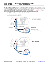
6502, Front Cover Removed
MS-8 to sonde
3/4” conduit to jct box
132
+12 VDC
GND
SDI-12
TB-1
Figure 8
Connector TB-1
detail
6508
Enter
Esc
Cal
6500
6500
ENVIRONMEN TA
L
ENVIRONMEN TA
L
MONITORINGMONITORING
SYSTEMSYSTEM
21.2 Temp
7.35 DO
6.53 pH
Junction
Box
sonde cable
w/ MS-8
Stream
Sonde
Breakout
up to 250 ‘
conduit
6507
6’ Patch cable
w/ MS-8
customer-supplied
3-conductor cable
1
3
2
+1
2
VDC
GND
SDI
-
12
TB-1
IMPORTANT!
GND on TB-1 is for signal common only. Do not connect to earth ground.
YSI Incorporated 6500 Environmental Process Monitor 12

Installation Section 2
2.5.2 AC POWER INPUT WIRING
The 6500 Monitor has a switching power supply and can operate on 100 to 240 VAC power.
When you remove the front panel of the 6500 Monitor, take care not to drop the cover since it is
not hinged to the Monitor. Refer to figure 8 for power installation.
Connect AC power to TB1-1, L1 and L2. Connect ground wire to one of the three 10-32
grounding screws using a lug (not provided). To meet compliance with UL3010, EN61010 and
CSA1010, install a power switch on the AC load line external to the 6500 Monitor (Note: AC
on/off power switch is not included with the 6500 Monitor package).
CAUTION!
The sensitivity and stability of the monitor will be impaired if the input wiring is not grounded.
Do not apply power to the Monitor until all electrical connections are verified and secure.
Figure 10 6500 Terminal Connections (6500 Cover Removed)
RS485 for
Modbus
RS232 for Modbus and
software upgrades
Single 12-pin connector
for relay outputs
A
C Power
connector
8-pin connectors (2)
for 4-20 mA outputs
Relays (4)...
soldered to PCB
L1 L2
Grounding
Screws (10-32)
B-
A
-
G
N
YSI Incorporated 6500 Environmental Process Monitor 13

Installation Section 2
Use the following precautions from UL 508 as a guide to safety for personnel and property.
¾ AC connections and grounding must be in compliance with UL 508 and/or local electrical
codes.
¾ The metal stiffener provides support and proper electrical continuity between conduit fittings.
¾ This type 4/4X enclosure requires a conduit hub or equivalent that provides watertight
connection, REF UL 508-26.10.
¾ Watertight fittings/hubs that comply with the requirements of UL 514B are to be used.
¾ Conduit hubs are to be connected to the conduit before the hub is connected to the enclosure,
REF UL 508.26.10.
¾ If the metal support plate is not used, plastic fittings must be used to prevent structural
damage to the Monitor. Also, the appropriate grounding lug and AWG conductor must be
used with the plastic fittings. When using plastic connectors and non-metallic liquid-tight
conduit note that the maximum conduit run length is 6 feet, REF NEC351-23-b3.
2.5.3 RELAY OUTPUT WIRING
The four (4) output relay connections are made to terminals 1 through 12 of TB-2. Relays may be
wired normally open (N.O.) or normally closed (N.C.). Use appropriate wire in terms of gauge
and insulation to adequately handle the voltage and current being switched by the relays. See
Appendix A, Specifications, for relay specifications. Do not use power at TB-1 as a source for
any of the relays in the 6500 system. Remember that relays are intended to activate alarms,
phone dialers and similar devices. The relays are
not intended to switch heavy loads.
4-20 MA CURRENT LOOP OUTPUT WIRING
The eight (8) 4-20 mA current output connections are made to TB3-1 through TB3-16. Use
Belden cable #8164 (4-conductor), #8168 (8-conductor) or equivalent between the 6500 Monitor
and the SCADA or recorder site.
RS232 AND RS485 TERMINALS
The RS232 port is used for 6500 Monitor software updates and optional Modbus interface. The
RS485 port can also be used for an optional Modbus interface. Neither of these connectors is
involved in the installation of the 6500 system.
YSI Incorporated 6500 Environmental Process Monitor 14

Installation Section 2
2.5.4 GROUNDING INFORMATION
This section contains important installation information regarding grounding of the 6500 Monitor
and 6-Series Sonde. The sonde is powered by the 6500 Monitor or by batteries (depending on
which sonde you have chosen) and will be operated with a “floating” ground reference. This
requires that the sonde
not be individually grounded. Grounding the sonde individually will
cause a “ground loop”; i.e. one conductor of the sonde output grounded common to both the
sonde and the meter. Grounding the sonde will cause significant performance problems with the
sensors and likely result in erroneous readings.
IMPORTANT!
Do not ground the sonde body.
2.5.5 SAFETY ISSUES
The electrical system must be grounded to avoid possible electrical shock or damage to the
equipment.
WARNING!
Turn off all power and assure power “lockout” before servicing to avoid contact with electrically
powered circuits.
To avoid possible electrical shock, do not touch other circuit components when making
adjustments to the 6500 Monitor circuit board. Disconnect external power to the unit before
connecting or disconnecting wiring.
2.5.6 LIGHTNING AND SURGE PROTECTION
Surge protectors are strongly recommended to protect from secondary surges and lightning on
outdoor installations.
Surge suppression devices should be located on the AC line supplying power to the 6500 Monitor
and any signal lines connecting the 6500 Monitor to alarms, a SCADA or other data collecting
device.
AC line voltage surge suppressors protect field equipment on any AC line to ground from damage
due to electrical transients induced in the interconnecting power lines from lightning discharges
and other high voltage surges. The unit should include noise filtering, common mode and normal
YSI Incorporated 6500 Environmental Process Monitor 15

Installation Section 2
mode suppression and nanosecond reaction time. Surge suppressors should be internally fused to
remove the load if the unit is overloaded or the internal protection fails.
Signal line suppressors protect 4-20 mA DC current loops, low voltage signals and relay outputs
from damage due to electrical transients induced in the signal lines from lightning discharges or
nearby electrical devices. Signal line suppressors should be installed at each end of an analog
loop. Relay outputs should be protected at the receiver end. Signal line suppressors should
consist of a three-element gas tube followed by metal oxide varistors and suppressor diodes. The
protective elements should be matched such that high-energy surge voltages trigger the gas surge
arrester, while low energy or surge voltages affect the MOV’s and suppressor diodes.
Lightning protection devices should be located as close to the sonde and monitor as possible and
wired in accordance with the National Electric Code in approved watertight enclosures. If the
distance between the sonde and the 6500 Monitor is less than 100 feet, only one protector per line
is needed, otherwise lightning protection should be installed at both ends of the wiring runs.
IMPORTANT NOTICE
This or any other installation procedure can not protect against a direct lightning strike. YSI
Incorporated cannot accept liability for damage due to lightning or secondary surges.
2.6 SEALANTS, DESICCANTS AND SECURING THE MONITOR
Since the 6500 Monitor, Breakout Box(s) and/or Junctions Box will likely be subjected to
environmental conditions that promote formation of condensation, it is very important to follow
the instructions below before securing the cover to your unit(s). This will prevent damage to the
electronic components within the Monitor and extend the life of the monitoring system.
Enclosed with shipment of every 6500 Environmental Monitoring System is industrial
encapsulant (conduit sealer), in a cartridge for your convenience. After all wiring is complete
apply the sealant to the conduit openings from the inside of the 6500 Monitor, Breakout Box
and/or Junction Box if applicable. This will help prevent moisture from entering the inside of the
6500 Monitor from conduit that was used for AC power cable or signal cables.
Note: If any of the conduit fittings were not used in the installation, remove the fitting and
replace with a 3/4” knockout plug provided with the unit. Two knockout plugs are provided.
Also enclosed with the 6500 Monitor is a box of desiccant packs. After all wiring is completed
and sealant applied, place two desiccant packs inside, near the bottom right of the Monitor before
securing the cover. This desiccant will consume any moisture captured during the closure to
provide a low humidity environment within the Monitor.
To complete the installation secure the cover of the 6500 Monitor using the four mounting screws
that you removed while doing the wiring operations. Note that the cover contains a captured
rubber gasket that provides the weatherproofing. Make certain that the gasket is in place and not
damaged. Check to make certain that the large blue ribbon cable is not trapped in the gasket
YSI Incorporated 6500 Environmental Process Monitor 16
/