Page is loading ...

Installation
Guide
And
Owner’s
Manual
Model:
CD30
CD36
READ
AND
SAVE
THIS
INSTRUCTION
MANUAL
ESSICK AIR PRODUCTS
5800 Murray Street, Little Rock, AR 72209
800-643-8341
Important: When receiving and unpacking, note
any damage on the freight bill. Any damage
claim must be filed with the carrier.
Power pack is separate – do not lose.
Purchased From:______________________
Date of Purchase:_____________________
Manual #: 70790

2
INSTALLATION OF EVAPORATIVE COOLERS
Preparation:
1. All electrical and ductwork must comply with local and federal codes.
2. Make arrangements to get the cooler to the roof (crane, hoist, etc.).
Location:
1. Plan ahead to avoid costly problems later. Avoid installation near kitchen exhausts and vent pipes, so the cooler will
not draw in fumes and odors.
2. Ensure that the roof or stand is strong enough to support the cooler. Operating weight, when the cooler is full of water,
is significantly heavier than shipping weight. CD30 operating weight: 1538 lbs. CD36 operating weight: 1588 lbs.
3. The cooler must be located so that it has a constant supply of fresh air. The cooler does not recirculate air.
Mounting:
1. The roof opening should be 70” x 46”.
2. It is recommended that you use the curb design shown on page 5.
3. The duct work or plenum box may be mounted to the curb.
Ductwork:
1. The most important rule in designing duct systems is: AN EVAPORATIVE COOLER DEPENDS ON A LARGE
VOLUME OF AIR COMING OUT OF THE DUCTWORK AT HIGH VELOCITY IN ORDER TO COOL PROPERLY.
2. DO NOT reduce the discharge opening of the cooler.
3. DO NOT undersize the ductwork and make it much smaller than the discharge opening.
In most cases, air conditioning ductwork is too small for a cooler.
4. Extra long ducts cause static pressure and diminish airflow. They, also, pick up heat and
diminish cooling.
5. Sharp or abrupt bends hinder air movement.
6. Poorly designed ceiling diffusers will ruin an otherwise successful installation. Install
diffusers that are specifically designed for use with evaporative coolers.
Motor Installation:
Now that the cooler is in place, mounted and level, remove the motor from its box and
examine it for damage. Make sure that the voltage, phase, etc. are correct. Installation
hardware can be found in the cooler installation bag. Mount the motor as shown. Do not
tighten the mounting bolts until after the belts are installed and tightened.
Motor Pulley Installation:
The motor pulley will be shipped with the motor.
1. Using a 5/32” hex wrench, loosen the set screws on either side of the
pulley and the one in between the jaws of the pulley.
2. Close the pulley (Hold the center of the pulley and screw the outside
jaws in towards the center).
3. Open each side of the pulley 3 turns.
4. Tighten the set screws to lock the moveable jaws in place. Tighten set
screws onto flat area, otherwise thread damage will occur.
5. Slide the pulley onto the motor shaft with the keyways aligned.
6. Insert the key.
7. Align motor pulley and blower pulley.
8. Tighten the center set screw to lock into place.
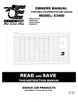
Belt Adjustment:
1. Place the belts over the motor pulley and roll them over the blower pulley.
2. Slide the motor back on its mount until belts are properly tensioned (1 to 1 ½” of
deflection with 5 pounds pressure applied).
3. Tighten motor mount bolts.
Adjustment
Set Screw
Adjustment
Set Screw
1" to 1 1/2"
Deflection With
5lbs Pressure

3
Reservoir
WARNING: To avoid the risk of fire, electric shock, or serious personal injury, be sure to disconnect power from
unit before cleaning or servicing.
CAUTION: To reduce the risk of fire or shock, DO NOT use this fan with any solid state speed control device.
Electrical Wiring:
Before attempting electrical wiring:
1. Local electrical codes must be followed.
2. Connecting the motor to the wrong voltage will void
the motor warranty.
3. The gauge of the wire used must be suitable for the
voltage, horsepower, and length of the wire.
4. For motors up to and including 2 H.P. 240V single
phase, use Essick Six (6) Position Wall Switch,
part number ECR-6.
5. For larger motors and all three phase applications,
the proper motor starters must be used to control the motor. Consult local codes.
6. GROUND THE COOLER CABINET TO A SUITABLE GROUND CONNECTION, to ensure safety.
7. IMPORTANT – An ammeter check must be done, to determine amperage draw on the motor, before the unit is placed
in service. Be sure to leave access to the wires for this check.
Overflow and Drain assembly:
1. Slide Rubber Gasket over Bushing.
2. Place Bushing through float hole (from top).
3. Thread Lock Nut onto Bushing (from bottom) and tighten. Caution: if Lock Nut is over
tightened, the Rubber Gasket may be crushed causing a leak.
4. Thread overflow tube into bushing and HAND TIGHTEN. If leaking occurs a thread sealant
may be used.
Bleed Off:
A Bleed Off kit has been provided with this unit. If “hard water” is to be supplied to this unit,
installing the Bleed Off will decrease maintenance requirements and prolong pad life.
Float Valve:
1. Place Threaded portion of Float Valve through float hole provided in cabinet or float mount
bracket.
2. Slide Fiber Washer over threads of Float Valve.
3. Thread Ring Nut onto Float Valve and tighten. Ensure Water outlet points
straight down.
4. Place Compression Nut and Ferrule over ¼” water line. Place water line
into end of Float Valve and tighten Compression Nut until snug. If leaking
occurs after water is turned on, snug down Compression Nut until leaking
stops.
5. When the water level is at the desired level (½” below top of overflow).
Adjust the height of the Float so that the Float Valve cuts off completely.
Use the Adjustment Screw to adjust Float height and bend the Float Arm
to make minor adjustments.

4
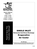
LOUVER
FILTER
Motor Pulley Adjustment: (IMPORTANT INFORMATION)
1. Find the amperage on the motor nameplate.
2. Install the louvers and ensure exhaust openings in the structure (usually windows) are open to the required position.
3. Start the cooler on high vent (no pump). Be sure the motor is turning in the correct direction. Three phase motors can
be wired to reverse the direction of the motor.
4. Using a clamp-type ammeter, check the motor amperage by clamping the ammeter around the incoming white lead.
5. If amperage is less than motor nameplate amps, remove the belts, loosen the adjustment set screws and close both
sides of the pulley one full turn. Tighten the adjustment set screws, replace the belts and check amperage again.
Repeat as necessary until amperage reads just under motor nameplate.
6. If amperage is too high, remove the belts, loosen the adjustment set screws and open both sides of the pulley one full
turn. Tighten the adjustment set screws, replace the belts and check amperage again. Repeat as necessary until
amperage reads just under motor nameplate.
7. When amperage reads correctly, adjust belt tension as necessary and recheck belt alignment.
Air Exhaust: (VERY IMPORTANT)
All of the air delivered by an evaporative cooler must be exhausted RAPIDLY. One square foot of exhaust is required for
every 200 CFM of air delivered.
Start Up:
After installing cooler and before filling with water
1. Open windows and doors or other exhaust openings in building.
2. Turn on cooler and check amperage at the incoming white lead, using clamp on ammeter. Refer to the motor pulley
adjustment instructions.
3. Turn on water to cooler and ensure that connections do not leak.
4. Fill pan to ½” below top of overflow tube and ensure that the float cuts off water completely.
5. Turn the switch to cool and check that water is coming from the water trays and that the pads are wetting evenly. There
are screws at the top of the louvers to level the water trays.
Maintenance:
CAUTION: Turn off all electrical power to this unit before opening or attempting any service.
THE MOTOR IS EQUIPPED WITH AUTOMATIC THERMAL PROTECTION. IF IT SHUTS OFF ON ITS OWN, FOR ANY
REASON, IT CAN START AGAIN WITHOUT WARNING!
Occasionally inspect your cooler for leaks, loose belt, blocked water lines, correct belt
alignment or excessive residue build up on the pads. Inspect cabinet for rust. If rust
spots appear, sand and paint with a high-grade paint.
Greasing:
Lube the blower bearings at least twice per year. Use standard bearing grease and
grease gun. Do not over grease and rupture the seals. Grease the blower motor if it is
equipped with grease fittings or use SAE 20W or 30W, non-detergent oil if it has oil
cups. Some motors are permanently lubricated at the factory.
Pad Replacement:
It is best to change pads at the end of the season. When old pads (covered by
minerals and salts) are left in the cooler during the wet winter months, there is a
greater possibility for corrosion.
1. Remove the louvers from the cooler.
2. Unhook pad retainers and remove.
3. Remove the old pads and discard.
4. Clean any dirt or sediment that has built up on louver. Inspect the water tray and
clean any dirt or sed iment that has built up in the water slots. If louver has rust
spots, sand and paint with a high-grade paint.
5. There are 2 pads used in each louver of the CD30 (one aspen and one filter) and 3
pads used in each louver of the CD36 (one aspen and two filters).
6. Hang the aspen pad over the saw teeth in the water trough and tuck into the louver
so there are no gaps where hot air can bypass.
7. Tuck the filter pad(s) into the louver, ensuring that there are no gaps that will allow
hot air to bypass.
8. Replace the pad retainers. Make sure that the top of the pad retainer pushes down
over the saw teeth, so the filters do not sag.
Greese
Fitting

5
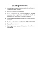
Suggested Cooler Curb Design
Replacement parts
1. 2x12 CONSTRUCTION
2. ALL TOLERANCES ±1/8"
3. ROOF OPENING 46" X 70"
ROOF
OPENING
1
10
8

6
Replacement Parts List
Item Part # Qty Description Item Part # Qty Description
1 512271 1 Top 506632 1 Replacement Pad Set (CD30)
2 70782 1 Bottom 70210 1 Replacement Pad Set (CD36)
3 70783 2 Blower Housing 19 70813 2 Blower Wheel
4 70694 2 Blower Cutoff 20 583001 3 Bearing
5 512491 1 Motor Mount 21 70763 1 Shaft
6 504309 3 Bearing Angle 22 583130 1 Blower Pulley (CD30)
7 70786 1 Water Shield 22 583132 1 Blower Pulley (CD36)
8 70785 1 Water Shield 23 582035 2 Belt (CD30) **
9 514239 6 Center Post 23 582138 2 Belt (CD36) **
10 500098 4 Corner Post 24 583051 1 Motor Pulley (CD30) **
11 501947 4 Lifting Bracket 24 583061 1 Motor Pulley (CD36) **
12 70784 2 Blower Brace 25 581035 1 Motor (CD30) **
13 70135 2 Splash Baffle 25 581036 1 Motor (CD36) **
14 70136 2 Splash Baffle 520073 1 Power Pack (CD30)
70815 10 Louver Assembly (CD30) 520074 1 Power Pack (CD36)
70816 10 Louver Assembly (CD36) 26 524198 1 Float
15 501352 10 Louver * 27 See Note 1 Pump (16000 CFM)
16 500677 10 Water Tray * 28 70488 1 Pump Bracket
17 524093 10 Evaporative Media * 29 598746 6’ Water Hose
17 70269 10 Water Barrier (CD30) * 30 70613 1 Overflow Assembly
17 70269 20 Water Barrier (CD36) * 31 514238 2 Center Brace
18 500603 10 Pad Retainer* 32 512265 2 Water Distributor
* Included in Louver Assembly. ** Included in Power Pack. Replacement pump part # dependent on voltage.
LIMITED WARRANTY
This warranty is extended to the original purchaser of an evaporative cooler installed and used under normal conditions.
It does not cover damages incurred through accident, neglect, or abuse by the owner. We do not authorize any person or
representative to assume for us any other or different liability in connection with this product.
TERMS AND CONDITIONS OF WARRANTY
For five years from date of installation, we will replace the original base assembly if water leakage should occur due to
rust out.
For one year from date of installation, we will replace any original component provided by Essick Air Products Inc., which
fails due to any defect in material or factory workmanship only.
EXCLUSIONS FROM WARRANTY
We are not responsible for replacement of cooler pads. These are disposable components and should be replaced
periodically. We are not responsible for any incidental or consequential damage resulting from any malfunction.
We are not responsible for any damage received from the use of water softeners, chemicals, descale material, plastic
wrap, or if a motor of higher horsepower than what is shown on the serial plate is used in the unit.
We are not responsible for the cost of service calls to diagnose cause of trouble, or labor charge to repair and/or the
replacement of parts.
HOW TO OBTAIN SERVICE UNDER THIS WARRANTY
CONTACT THE Dealer where you purchased the evaporative cooler. If for any reason you are not satisfied with the
response from the Dealer, contact the Customer Service Department: Essick Air Products Inc. 5800 Murray Street, Little
Rock, Arkansas 72209 or phone (800) 643-8341.
THIS LIMITED WARRANTY APPLIES TO ORIGINAL PURCHASER ONLY
/