Page is loading ...

User Guide
DXP HD 4K PLUS Series
Matrix Switchers
4K HDMI Switchers
68-2939-01 Rev. J
12 20

Safety Instructions
Safety Instructions • English
WARNING: This symbol, , when used on the product, is intended to
alert the user of the presence of uninsulated dangerous voltage within
the product’s enclosure that may present a risk of electric shock.
ATTENTION: This symbol, , when used on the product, is intended
to alert the user of important operating and maintenance (servicing)
instructions in the literature provided with the equipment.
For information on safety guidelines, regulatory compliances, EMI/EMF
compatibility, accessibility, and related topics, see the Extron Safety and
Regulatory Compliance Guide, part number 68-290-01, on the Extron
website, www.extron.com.
Sicherheitsanweisungen • Deutsch
WARNUNG: Dieses Symbol auf dem Produkt soll den Benutzer
darauf aufmerksam machen, dass im Inneren des Gehäuses dieses
Produktes gefährliche Spannungen herrschen, die nicht isoliert sind und
die einen elektrischen Schlag verursachen können.
VORSICHT: Dieses Symbol auf dem Produkt soll dem Benutzer in
der im Lieferumfang enthaltenen Dokumentation besonders wichtige
Hinweise zur Bedienung und Wartung (Instandhaltung) geben.
Weitere Informationen über die Sicherheitsrichtlinien, Produkthandhabung,
EMI/EMF-Kompatibilität, Zugänglichkeit und verwandte Themen finden Sie in
den Extron-Richtlinien für Sicherheit und Handhabung (Artikelnummer
68-290-01) auf der Extron-Website, www.extron.com.
Instrucciones de seguridad • Español
ADVERTENCIA: Este símbolo, , cuando se utiliza en el
producto, avisa al usuario de la presencia de voltaje peligroso sin aislar
dentro del producto, lo que puede representar un riesgo de descarga
eléctrica.
ATENCIÓN: Este símbolo, , cuando se utiliza en el producto,
avisa al usuario de la presencia de importantes instrucciones de uso y
mantenimiento recogidas en la documentación proporcionada con el
equipo.
Para obtener información sobre directrices de seguridad, cumplimiento
de normativas, compatibilidad electromagnética, accesibilidad y temas
relacionados, consulte la Guía de cumplimiento de normativas y seguridad
de Extron, referencia 68-290-01, en el sitio Web de Extron, www.extron.com.
Instructions de sécurité • Français
AVERTISSEMENT : Ce pictogramme, , lorsqu’il est utilisé sur le
produit, signale à l’utilisateur la présence à l’intérieur du boîtier du
produit d’une tension électrique dangereuse susceptible de provoquer
un choc électrique.
ATTENTION : Ce pictogramme, , lorsqu’il est utilisé sur le produit,
signale à l’utilisateur des instructions d’utilisation ou de maintenance
importantes qui se trouvent dans la documentation fournie avec le
matériel.
Pour en savoir plus sur les règles de sécurité, la conformité à la
réglementation, la compatibilité EMI/EMF, l’accessibilité, et autres sujets
connexes, lisez les informations de sécurité et de conformité Extron, réf.
68-290-01, sur le site Extron, www.extron.com.
Istruzioni di sicurezza • Italiano
AVVERTENZA: Il simbolo, , se usato sul prodotto, serve ad
avvertire l’utente della presenza di tensione non isolata pericolosa
all’interno del contenitore del prodotto che può costituire un rischio di
scosse elettriche.
ATTENTZIONE: Il simbolo, , se usato sul prodotto, serve ad avvertire
l’utente della presenza di importanti istruzioni di funzionamento e
manutenzione nella documentazione fornita con l’apparecchio.
Per informazioni su parametri di sicurezza, conformità alle normative,
compatibilità EMI/EMF, accessibilità e argomenti simili, fare riferimento
alla Guida alla conformità normativa e di sicurezza di Extron, cod. articolo
68-290-01, sul sito web di Extron, www.extron.com.
I

Copyright
© 2018-2020 Extron. All rights reserved. www.extron.com
Trademarks
All trademarks mentioned in this guide are the properties of their respective owners.
The following registered trademarks (
®
), registered service marks (
SM
), and trademarks (
TM
) are the property of RGBSystems, Inc. or Extron
(see the current list of trademarks on the Terms of Use page at www.extron.com):
Registered Trademarks
(
®
)
Extron, Cable Cubby, ControlScript, CrossPoint, DTP, eBUS, EDID Manager, EDID Minder, eLink, Flat Field, FlexOS, Glitch Free, GlobalConfigurator,
GlobalScripter, GlobalViewer, Hideaway, HyperLane, IPIntercom, IPLink, KeyMinder, LinkLicense, LockIt, MediaLink, MediaPort, NAV,
NetPA, PlenumVault, PoleVault, PowerCage, PURE3, Quantum, ShareLink, Show Me, SoundField, SpeedMount, SpeedSwitch, StudioStation,
SystemINTEGRATOR, TeamWork, TouchLink, V-Lock, VideoLounge, VN-Matrix, VoiceLift, WallVault, WindoWall, XPA, XTP, XTPSystems, and ZipClip
Registered Service Mark
(SM)
: S3 Service Support Solutions
Trademarks
(
™
)
AAP, AFL (Accu-RATEFrameLock), ADSP(Advanced Digital Sync Processing), AVEdge, CableCover, CDRS(ClassD Ripple Suppression), Codec
Connect, DDSP(Digital Display Sync Processing), DMI (DynamicMotionInterpolation), DriverConfigurator, DSPConfigurator, DSVP(Digital Sync
Validation Processing), EQIP, Everlast, FastBite, Flex55, FOX, FOXBOX, IP Intercom HelpDesk, MAAP, MicroDigital, Opti-Torque, PendantConnect,
ProDSP, QS-FPC(QuickSwitch Front Panel Controller), RoomAgent, Scope-Trigger, SIS, SimpleInstructionSet, Skew-Free, SpeedNav, Triple-Action
Switching, True4K, True8K, Vector™ 4K, WebShare, XTRA, and ZipCaddy

FCC Class A Notice
This equipment has been tested and found to comply with the limits for a Class A digital
device, pursuant to part15 of the FCC rules. The ClassA limits provide reasonable
protection against harmful interference when the equipment is operated in a commercial
environment. This equipment generates, uses, and can radiate radio frequency energy and,
if not installed and used in accordance with the instruction manual, may cause harmful
interference to radio communications. Operation of this equipment in a residential area is
likely to cause interference. This interference must be corrected at the expense of the user.
NOTE: For more information on safety guidelines, regulatory compliances, EMI/EMF
compatibility, accessibility, and related topics, see the Extron Safety and Regulatory
Compliance Guide on the Extron website.
VCCI-A Notice
この装置は、クラスA情報技術装置です。 この装置を家庭環境で使用すると、電波妨害を引き
起こすことがあります。 その場合には使用者が適切な対策を講ずるよう要求されることがあります。
VCCI-A
Battery Notice
This product contains a battery. Do not open the unit to replace the battery. If the
battery needs replacing, return the entire unit to Extron (for the correct address, see the
Extron Warranty section on the last page of this guide).
CAUTION: Risk of explosion. Do not replace the battery with an incorrect type. Dispose
of used batteries according to the instructions.
ATTENTION : Risque d’explosion. Ne pas remplacer la pile par le mauvais type de
pile. Débarrassez-vous des piles usagées selon le mode d’emploi.

Conventions Used in this Guide
Notifications
The following notifications are used in this guide:
WARNING: Potential risk of severe injury or death.
AVERTISSEMENT : Risque potentiel de blessure grave ou de mort.
CAUTION: Risk of minor personal injury.
ATTENTION : Risque de blessuremineure.
ATTENTION:
• Risk of property damage.
• Risque de dommages matériels.
NOTE: A note draws attention to important information.
Software Commands
Commands are written in the fonts shown here:
^AR Merge Scene,,0p1 scene 1,1 ^B 51 ^W^C.0
[01] R 0004 00300 00400 00800 00600 [02] 35 [17] [03]
E X! *X1&* X2)* X2#* X2! CE}
NOTE: For commands and examples of computer or device responses used in this
guide, the character “0” is the number zero and “O” is the capital letter “o.”
Computer responses and directory paths that do not have variables are written in the font
shown here:
Reply from 208.132.180.48: bytes=32 times=2ms TTL=32
C:\Program Files\Extron
Variables are written in slanted form as shown here:
ping xxx.xxx.xxx.xxx —t
SOH R Data STX Command ETB ETX
Selectable items, such as menu names, menu options, buttons, tabs, and field names are
written in the font shown here:
From the
File menu, select New.
Click the
OK button.
Specifications Availability
Product specifications are available on the Extron website, www.extron.com.
Extron Glossary of Terms
A glossary of terms is available at http://www.extron.com/technology/glossary.aspx.


DXP HD 4K PLUS Series • Contents
vii
Contents
Introduction............................................................ 1
About this Guide
................................................. 1
About the DXP HD 4K PLUS Series Matrix
Switchers
.......................................................... 1
Features ............................................................. 2
EDID Minder ....................................................... 4
Managing EDID............................................... 4
Factory Loaded EDID
.................................... 4
Assigned Output EDID
.................................... 4
Application Diagrams .......................................... 8
Installation ............................................................ 10
Rear Panels
...................................................... 10
DXP 168 and 1616 PLUS Rear Panel ........... 11
DXP 44, 84, and 88 PLUS Rear Panel .......... 11
DXP 42 PLUS Rear Panel
............................. 11
Legend for Figures 4, 5, and 6
...................... 11
Rear Panel Features ..................................... 12
Connecting to the LAN Port .............................. 14
Connecting to the Remote RS-232 Port ........... 15
Connecting Power to the
DXP 42 HD 4K PLUS
...................................... 16
Securing the HDMI Connectors Using the
LockIt HDMI Cable Lacing Bracket
.................. 18
Operation .............................................................. 19
Definitions ......................................................... 19
Front Panel Controls and Indicators .................. 20
Front Panel Buttons and LEDs ...................... 20
DXP 168 and 1616 HD 4K PLUS Front
Panel
........................................................... 21
DXP 44, 84, and 88 HD 4K PLUS Front
Panel ........................................................... 21
DXP 42 HD 4K PLUS Front Panel
................. 21
Front Panel Features ..................................... 22
Powering On .................................................... 25
Self-test
........................................................ 25
Creating or Changing a Configuration
............... 26
DXP 168 and 1616 PLUS Configuration ....... 27
DXP 44, 84, and 88 PLUS Configuration ...... 28
Creating Ties — DXP 168 and 1616 PLUS ... 29
Creating Ties —
DXP 44, 84, and 88 PLUS ........................... 36
Creating Ties — DXP 42 PLUS ..................... 40
Saving and Recalling Presets ........................... 42
Saving a Preset —
DXP 168 and 1616 PLUS ............................ 42
Saving a Preset —
DXP 44, 84, and 88 PLUS ........................... 44
Muting and Unmuting Outputs from the Front
Panel ............................................................... 46
Muting Outputs —
DXP 168 and 1616 PLUS ............................ 46
Muting Outputs —
DXP 44, 84, and 88 PLUS ........................... 48
Locking and Unlocking the Front Panel
(Executive Modes) ........................................... 49
Setting Lock Modes —
DXP 168 and 1616 PLUS ............................ 50
Setting Lock Modes —
DXP 44, 84, and 88 PLUS ........................... 51
Power Save Modes .......................................... 53
Selecting the Remote RS-232 Port Baud
Rate ................................................................ 53
Selecting the Baud Rate for
DXP 168 and 1616 PLUS ............................ 53
Selecting the Baud Rate for DXP 44, 84,
and 88 PLUS ............................................... 54
Setting the Button Background Illumination —
DXP 168 and 1616 PLUS Only ........................ 55
Resetting .......................................................... 55
Resetting the System from the Front Panel ... 55
Resetting Using the Front or Rear Panel
Reset Button ............................................... 57
Troubleshooting ................................................ 59

DXP HD 4K PLUS Series • Contents viii
Configuration Worksheets................................. 60
Worksheet Example 1: System
Equipment — 8 Inputs and Outputs ............ 60
Worksheet Example 2: Daily
Configuration — 8 Inputs and Outputs ........ 61
Worksheet Example 3: Test
Configuration — 8 Inputs and Outputs ........ 61
Worksheet Example 1: System
Equipment — 16 Inputs and Outputs .......... 62
Worksheet Example 2: Daily
Configuration — 16 Inputs and Outputs ...... 63
Worksheet Example 3: Test Configuration ..... 63
Worksheet Form — 8 Inputs and Outputs ..... 64
Worksheet Form — 16 Inputs and Outputs ... 65
SIS Configuration and Control ........................ 66
Connection Methods ........................................ 66
Host and Matrix Switcher Communication ........ 66
Copyright Information ................................... 66
Device-Initiated Messages ............................ 67
Error Responses ........................................... 68
Connection Timeouts ................................... 68
Number of Connections ................................ 68
SIS Overview .................................................... 69
Using the Command and Response
Tables .......................................................... 69
Verbose Mode .............................................. 69
Symbol Definitions ........................................ 70
Command and Response Table —
DXP 44, 84, 88, 168, and 1616 PLUS ............. 75
Command and Response Table — DXP 42 ...... 91
CEC SIS Commands ..................................... 102
CEC Symbol Definitions .............................. 102
Configuration Software ................................... 106
Software Installation........................................ 106
Software Download Center Page ................ 106
PCS Product Page ..................................... 108
Software Connection ...................................... 109
Device Discovery Panel ............................... 109
TCP/IP Panel .............................................. 111
Offline Device Preview ................................. 112
Help File Access ............................................. 113
Internal Web Page ............................................ 114
Web Page Access .......................................... 114
Web Page Components ................................. 115
Device Info Panel ........................................ 116
Inputs Panel................................................ 116
RS-232 Panel ............................................. 117
Device Status Panel .................................... 117
Outputs Panel ............................................. 119
Roles and Permissions Panel ...................... 119
Network Settings Panel .............................. 121
Firmware Panel ........................................... 122
Reference Information .................................... 123
Mounting the Switcher .................................... 123
UL Guidelines for Rack Mounting ................ 123
Mounting Procedures ................................. 124
Downloading Updated Firmware ..................... 125
Network Setup ............................................... 126
What is an IP Address?............................... 126
Choosing IP Addresses .............................. 127
Subnet Mask .............................................. 127
Pinging for the IP Address .......................... 128
Connecting as a Telnet Client ...................... 129
Subnetting, a Primer ................................... 131

DXP HD 4K PLUS Series • Introduction 1
Introduction
This section gives an overview of the Extron DXP HD 4K PLUS matrix switchers, describes
significant features of the series, and provides application diagrams. Topics in this section
include:
• About this Guide
• About the DXP HD 4K PLUS Series Matrix Switchers
• Features
• EDID Minder
• Application Diagrams
About this Guide
This guide contains installation, configuration, and operating information for the
DXP HD 4K PLUS Series matrix switchers. In this guide, the terms “DXP PLUS,”
“switcher,” and “DXP PLUS matrix switcher” are used interchangeably to refer to any or all
DXP HD 4K PLUS Series models.
About the DXP HD 4K PLUS Series Matrix Switchers
The DXP HD 4K PLUS Series are high performance HDMI matrix switchers for computer
and video resolutions up to 4K @ 60 Hz. They support HDMI 2.0b specifications, including
data rates up to 18 Gbps, HDR Deep Color up to 12-bit, 3D, and HD lossless audio
formats. These switchers are HDCP 2.3 compliant and incorporate Extron technologies
including SpeedSwitch, EDID Minder, and Key Minder. HDMI input equalization and output
regeneration ensure reliable system operation. Digital audio can be de-embedded from any
input and assigned to digital or analog stereo outputs. The following models are available in
fixed matrix sizes:
• DXP 42 HD 4K PLUS — 4 inputs by 2 outputs with 2 audio outputs
• DXP 44 HD 4K PLUS — 4 inputs by 4 outputs with 2 audio outputs
• DXP 84 HD 4K PLUS — 8 inputs by 4 outputs with 2 audio outputs
• DXP 88 HD 4K PLUS — 8 inputs by 8 outputs with 2 audio outputs
• DXP 168 HD 4K PLUS — 16 inputs by 8 outputs with 4 audio outputs
• DXP 1616 HD 4K PLUS — 16 inputs by 16 outputs with 4 audio outputs
The DXP HD 4K PLUS Series are designed for use with computers equipped with 4K
graphics cards, media players and similar signal sources, and 4K native resolution displays.
With a maximum data rate of 18 Gbps, the switchers support computer and video
resolutions up to 4096x2160 @ 60 Hz with 8-bit color in 4:4:4 color space.
To maintain signal integrity, these switchers feature automatic cable equalization on inputs
and output reclocking to reshape and restore timing of the video signal at each HDMI
output. These features combined with Extron Pro Series High Speed HDMI Cables allow
longer 4K signal runs, reducing the need for additional signal conditioning equipment
by compensating for weak source signals or signal loss on long cable runs. Additionally,
+5 VDC, 250 mA power is available on the outputs for peripheral devices.

DXP HD 4K PLUS Series • Introduction 2
Features
• Supports computer and video resolutions up to and including 4K, including
1080p @ 60 Hz Deep Color.
• Supports HDMI 2.0b specification features, including data rates up to 18 Gbps,
Deep Color up to 12-bit, 3D, and HD lossless audio formats.
• HDMI audio de-embedding with digital S/PDIF (Sony/Philips Digital Interface)
and analog stereo audio outputs (DXP 44, 84, 88, 168, and 1616 PLUS only) —
The DXP HD 4K PLUS Series can extract embedded HDMI two-channel LPCM audio
to S/PDIF digital and analog audio outputs. It can also extract Dolby
®
or DTS
®
encoded
bitstream audio to the S/PDIF outputs. The matrix switchers feature multiple sets of S/
PDIF and analog outputs, supporting audio assignment from any HDMI input source.
• S/PDIF audio output (DXP 44, 84, 88, 168, and 1616 PLUS only) — The
DXP HD 4K PLUS Series includes S/PDIF outputs for 2-channel LPCM audio or
encoded standard definition bitstream audio for Dolby or DTS multi-channel surround
sound.
• DXP 44, 84, and 88 PLUS have two S/PDF connectors.
• DXP 168 and 1616 PLUS have four S/PDIF connectors.
• HDCP 2.3 compliant — Ensures display of content-protected media and
interoperability with other HDCP-compliant devices.
• Consumer Electronics Control (CEC) capability — Standard, built-in CEC
commands can be triggered to control displays or other AV devices connected
over HDMI. The ability to control specific functions, such as power on and off,
input selection, and volume level are dependent on implementation by the device
manufacturer.
• User-selectable HDCP authorization — Allows individual inputs to appear HDCP
compliant or non-HDCP compliant to the connected source, which is beneficial if the
source automatically encrypts all content when connected to an HDCP-compliant
device. Protected material is not passed in non-HDCP mode.
• SpeedSwitch Technology provides high switching speed for HDCP-encrypted
content.
• Key Minder continuously verifies HDCP compliance for quick, reliable
switching — Key Minder authenticates and maintains continuous HDCP encryption
between input and output devices to ensure quick and reliable switching in professional
AV environments, while enabling simultaneous distribution of a single source to one or
more displays.
• HDCP authentication and signal presence LED indicators — Front panel LED
indicators for signal presence and HDCP authentication provide real time feedback and
monitoring of key performance parameters.
• EDID Minder automatically manages EDID communication between connected
devices — EDID Minder ensures that all sources power up properly and reliably output
content for display (available through Product Configuration Software [PCS]).
• Support for High Dynamic Range video (HDR) — Enables greater contrast range
and wider color gamut by providing the necessary video bandwidth, color depth, and
metadata interchange capability for HDR video.
• Supports DDC transmissions
• HDMI to DVI Interface Format Correction — Automatically reformats HDMI source
signals for output to a connected DVI display.

DXP HD 4K PLUS Series • Introduction 3
• Automatic input cable equalization — Equalizes inputs to support signals up to 4K
resolution at greater distances.
• Automatic output reclocking — Reshapes and restores timing of HDMI signals at
each output, enabling transmission over long HDMI cables.
• Provides +5 VDC, 250 mA power on the HDMI outputs for external peripheral
devices
• Global presets (DXP 44, 84, 88, 168, and 1616 PLUS only) — Up to 16
(DXP 88 PLUS series) or 32 (DXP 1616 PLUS series) frequently used I/O configurations
can be saved and recalled using the front panel buttons, Ethernet, USB, or serial
control. This time-saving feature allows I/O configurations to be set up and stored in
memory for future use.
• Rooming (DXP 44, 84, 88, 168, and 1616 PLUS only) — The DXP HD 4K 44, 84,
88, 168, and 1616 PLUS models can be programmed to group selected outputs into
specific “rooms,” each with its own set of unique presets. Each room can support up to
16 outputs. A total of 10 rooms, with 10 presets per room, are available.
• QS-FPC QuickSwitch Front Panel Controller — Discrete buttons for each input and
output allow for simple, intuitive operation.
• View I/O mode — Discrete LEDs for each input button allow easy viewing of actively
connected inputs and outputs for ease in troubleshooting.
• Output volume control — Provides the capability to mute one or all outputs at
any time. This allows, for example, content to be viewed on a local monitor prior to
appearing on the main presentation display.
• Audio breakaway (DXP 44, 84, 88, 168, and 1616 PLUS only) — Provides the
capability to break an analog audio signal away from its corresponding video signal and
route it to the audio outputs, allowing the analog audio channels to be operated as a
separate switcher.
• Ethernet monitoring and control — Can be monitored, managed, or controlled over
a LAN, WAN, or the Internet using standard TCP/IP protocols.
• RS-232 control port — The matrix switcher can be integrated into a control system.
Extron products use the SIS (Simple Instruction Set) command protocol, a set of basic
ASCII code commands that allow for quick and easy programming.
• Product Configuration Software (PCS) — The Extron PCS program provides a
means of configuring multiple products using a single software application.
• Front panel USB configuration port — Enables setup, configuration, and firmware
updating without having to access the rear panel.
• Front panel security lockout (executive mode) — Prevents unauthorized use in
non-secure environments.
• Rack-mountable full rack width metal enclosure, with a height of 1 inch
(DXP 42 PLUS) 1U (DXP 44, 84, and 88) or 2U (DXP 168 and 1616 PLUS)
• Includes Lockit HDMI cable lacing brackets — Secure HDMI cables to the HDMI
connectors.
• Power save mode (DXP 44, 84, 88, 168, and 1616 PLUS only) — The unit can be
placed in a low power standby state to conserve energy when not in use.
• Highly reliable, energy-efficient internal universal power supply — Provides
worldwide power compatibility, with high demonstrated reliability and low power
consumption for reduced operating costs.

DXP HD 4K PLUS Series • Introduction 4
EDID Minder
EDID Minder ensures that each source connected to an input sees the EDID of a display,
even when that source is not selected for a display.
Depending on the selected EDID mode, the DXP PLUS can store the EDID of the connected
display automatically (default), or you can manually select a factory EDID file from a pre-
determined list. This EDID file is written to a file located at each selected input within the
supported video group. All inputs support unique EDID emulation, HDCP, and HDCP
Authorization enabling or disabling.
Managing EDID
You can manage EDID files using PCS (see the DXP HD 4K PLUS Series Help file). You
can also select and import EDID files using SIS commands (see the EDID Commands on
page93). (EDID cannot be managed via the front panel.)
Factory Loaded EDID
The factory loaded EDID stored on the unit are taken from the Extron EDID Standards
Folder, which is created on the DXP PLUS by PCS. You can choose an EDID file from the
folder link via PCS or SIS commands. The HDMI inputs support digital Extron EDID files that
are 2 blocks or 256 bytes. The second block contains audio information. The HDMI EDID
support 2-channel PCM audio. The default Extron factory EDID file 1080p @ 60 Hz.
Assigned Output EDID
The DXP PLUS has four or eight memory slots, depending on the model, for the EDID of the
display connected to the output of the matrix switcher.
The unit automatically saves EDID information from the HDMI outputs whenever an output is
connected. The EDID information is saved until a new display or device is detected, and the
new EDID information overwrites the previous one. The EDID of each output is saved and
made available to any input slot. Assigned output EDID can be directly assigned to any input
via PCS.

DXP HD 4K PLUS Series • Introduction 5
EDID tables for DXP HD 4K PLUS
DXP 1616 PLUS (16 x 16) HD 4K PLUS and DXP 168 (16 x 8) HD 4K PLUS
SIS Variable
X5@
EDID Memory
Slot
Default EDID File Details
1
Input 1 (Store) EXN_HDMI_1080p60_2Ch.bin Manually populated using PCS
2
Input 2 (Store)
3
Input 3 (Store)
4
Input 4 (Store)
5
Input 5 (Store)
6
Input 6 (Store)
7
Input 7 (Store)
8
Input 8 (Store)
9
Input 9 (Store)
10
Input 10 (Store)
11
Input 11 (Store)
12
Input 12 (Store)
13
Input 13 (Store)
14
Input 14 (Store)
15
Input 15 (Store)
16
Input 16 (Store)
17
Output 1 N/A Automatically populated with
the sink EDID from the output
18
Output 2
19
Output 3
20
Output 4
21
Output 5
22
Output 6
23
Output 7
24
Output 8
25
Output 9
26
Output 10
27
Output 11
28
Output 12
29
Output 13
30
Output 14
31
Output 15
32
Output 16

DXP HD 4K PLUS Series • Introduction 6
DXP 88 HD 4K PLUS (8 x 8) and DXP 84 HD 4K PLUS (8 x 4)
SIS Variable
X5@
EDID Memory Slot Default EDID File Details
1 Input 1 (store) EXN_HDMI_1080p60_2Ch.bin Manually populated via PCS
2 Input 2 (store) EXN_HDMI_1080p60_2Ch.bin Manually populated via PCS
3 Input 3 (store) EXN_HDMI_1080p60_2Ch.bin Manually populated via PCS
4 Input 4 (store) EXN_HDMI_1080p60_2Ch.bin Manually populated via PCS
5 Input 5 (store) EXN_HDMI_1080p60_2Ch.bin Manually populated via PCS
6 Input 6 (store) EXN_HDMI_1080p60_2Ch.bin Manually populated via PCS
7 Input 7 (store) EXN_HDMI_1080p60_2Ch.bin Manually populated via PCS
8 Input 8 (store) EXN_HDMI_1080p60_2Ch.bin Manually populated via PCS
9 Output 1 N/A Automatically populated with
sink EDID from output 1
10 Output 2 N/A Automatically populated with
sink EDID from output 2
11 Output 3 N/A Automatically populated with
sink EDID from output 3
12 Output 4 N/A Automatically populated with
sink EDID from output 4
13 Output 5 N/A Automatically populated with
sink EDID from output 5
14 Output 6 N/A Automatically populated with
sink EDID from output 6
15 Output 7 N/A Automatically populated with
sink EDID from output 7
16 Output 8 N/A Automatically populated with
sink EDID from output 8

DXP HD 4K PLUS Series • Introduction 7
DXP 44 HD 4K PLUS (4 x 4)
SIS Variable
X5@
EDID Memory Slot Default EDID File Details
1 Input 1 (store) EXN_HDMI_1080p60_2Ch.bin Manually populated via PCS
2 Input 2 (store) EXN_HDMI_1080p60_2Ch.bin Manually populated via PCS
3 Input 3 (store) EXN_HDMI_1080p60_2Ch.bin Manually populated via PCS
4 Input 4 (store) EXN_HDMI_1080p60_2Ch.bin Manually populated via PCS
5 Output 1 N/A Automatically populated with
sink EDID from output 1
6 Output 2 N/A Automatically populated with
sink EDID from output 2
7 Output 3 N/A Automatically populated with
sink EDID from output 3
8 Output 4 N/A Automatically populated with
sink EDID from output 4
DXP 42 HD 4K PLUS (4 x 2)
SIS Variable
X5@
EDID Memory Slot Default EDID File Details
1 Input 1 (store) EXN_HDMI_1080p60_2Ch.bin Manually populated via PCS
2 Input 2 (store) EXN_HDMI_1080p60_2Ch.bin Manually populated via PCS
3 Input 3 (store) EXN_HDMI_1080p60_2Ch.bin Manually populated via PCS
4 Input 4 (store) EXN_HDMI_1080p60_2Ch.bin Manually populated via PCS
5 Output 1 N/A Automatically populated with
sink EDID from output 1
6 Output 2 N/A Automatically populated with
sink EDID from output 2

DXP HD 4K PLUS Series • Introduction 8
Application Diagrams
LAN
LAN
POWER
12V
1.5A MAX
INPUTS
1
HDMI
2
HDMI
3
HDMI
4
HDMI
OUTPUTS
1
HDMI/CEC
2
HDMI/CEC
AUDIO OUTPUTS
L
3
R L
4
R
Tx
RS-232
Rx G
REMOTE
MODEL 80
FLAT PANEL
ShareLink Pro 1000
HD WIN
STANDBY
SCREEN
DECODER
HD PASS
HDMI DECODER
SIGNAL
HDCP
CONFIG
OUTPUTINPUT
HDMI
WINDOW
HDMI
PASS-THROUGH
1 2
USB
WiFi
1 2 3 4
LAN
POWER
12V
1A MAX
G
Tx Rx RTSCTS
COM 1
G
Tx Rx
COM 2
V C G
VOL
RELAYS
1 2 C
1 2 3 4 G
DIGITAL I/O
PWR OUT = 6W
eBUS
+V + S
-S
G
LAN
IPCP PRO 250
IR/S
S G
Laptop
Tablet
Smartphone
Wireless Access Point
Videoconferencing PC
Shure MXA310
Table Mic
4K Display
Logitech
Rally Camera
USB
EthernetEthernet/PoE
Ethernet
RS-232
Ethernet
Ethernet
Audio Audio
HDMI
HDMIHDMI
HDMI
HDMIHDMI
Extron
TLP Pro 1025T
10" Tabletop TouchLink
Pro Touchpanel
Extron
IPCP Pro 250
IP Link Pro
Control Processor
Extron
SB 33 A
Sound Bar
Extron
ShareLink Pro 1000
Wireless and Wired
Collaboration Gateway
Extron
DXP 42 HD 4K PLUS
4K/60 HDMI Matrix Switcher
with Audio De-Embedding
Laptop Laptop
USB
HDMI
Capture
Ethernet
Ethernet
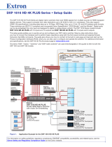
Figure 1. Application for a DXP 42 HD 4K PLUS
eBUS
FLEX I/O
RELAYSIR/SERIALCOM
12 VDC
LAN
+V
TxRx G TxRx G Tx Rx G Tx Rx G S G S G S G S GRTSCTS
+ - + -
+ - + -
-S G
PWR OUT = 12W
+S
S G S G S G S G
TxRx G TxRx G Tx Rx G Tx Rx G RTS CTS
1 2 3 4 G
1 2 3 4
5 6 7 8
1
1 2 3 4
5 6 7 8
2 3 7
4 5 6 8
1 2
3
100-240V ~ 50-60Hz
5A MAX
SWITCHED 12 VDC
40W MAX TOTAL
4
IPCP PRO 550
100-240V --A MAX
50-60 Hz
USB STORAGE
RESET
LAN
1
3
B-Y
R-Y VID
/Y
4
HDMI
HDMI
HDMI
AUDIO
L R
L R
HDMI
LOOPOUT
2
INPUTS-CH A
INPUTS-CH B
OUTPUTS
SMP 351
1 2 3 4 G
DIGITAL I/O
Tx Rx
RS-232
G
REMOTE
AUDIOL R
AUDIOL R
MOUSE /
KEYBOARD
1
2
100-240V --A MAX
50-60 Hz
USB STORAGE
RESET
LAN
1
3
B-Y
R-Y VID
/Y
4
HDMI
HDMI
HDMI
AUDIO
L R
L R
HDMI
LOOPOUT
2
INPUTS-CH A
INPUTS-CH B
OUTPUTS
SMP 351
1 2 3 4 G
DIGITAL I/O
Tx Rx
RS-232
G
REMOTE
AUDIOL R
AUDIOL R
MOUSE /
KEYBOARD
1
2
DXP 88 HD 4K PLUS
S/PDIF
1
2
AUDIO OUTPUTS
OUTPUTS
INPUTS
100-240V ~ 1.0A MAX
50-60 Hz
1
5
2
6
3
7
4
8
1
5
2
6
3
7
4
8
L
R
REMOTE LAN
Tx Rx G
RESET
INPUT
OFF
SEND
POWER
STATUS
OUTPUT
LINK
DTP2 T 211
CONFIG
POWER
12V
--A MAX
AUDIO
INPUTS
SIG LINK
DTP2 OUT
OVER DTP2
RS-232
IR
TxRx TxRxG
INPUT
OFF
SEND
POWER
STATUS
OUTPUT
LINK
DTP2 T 211
CONFIG
POWER
12V
--A MAX
AUDIO
INPUTS
SIG LINK
DTP2 OUT
OVER DTP2
RS-232
IR
TxRx TxRxG
INPUT
OFF
SEND
POWER
STATUS
OUTPUT
LINK
DTP2 R 211
CONFIG
L
RS-323 IR
TxRx TxRxG
R
POWER
12V
--A MAX
AUDIO
OUTPUTS
OVER DTP2
SIG LINK
DTP2 IN
V
C
G
10V
50mA
REMOTE
STANDBY
TIMER OFF
G
R
CLASS 2 WIRING
MPA 601-70V
70V OUTPUT
L
(SUMMED)
(SUMMED)
R
R
L
POWER
12V
1.3A MAX
INPUTS
INPUT
OFF
SEND
POWER
STATUS
OUTPUT
LINK
DTP2 R 211
CONFIG
L
RS-323 IR
TxRx TxRxG
R
POWER
12V
--A MAX
AUDIO
OUTPUTS
OVER DTP2
SIG LINK
DTP2 IN
V
C
G
10V
50mA
REMOTE
STANDBY
TIMER OFF
G
R
CLASS 2 WIRING
MPA 601-70V
70V OUTPUT
L
(SUMMED)
(SUMMED)
R
R
L
POWER
12V
1.3A MAX
INPUTS
RS-232
!
1
@
2
#
3
$
4
%
5
^
6
&
7
*
8
(
9
)
0
_
-
+
=
|
\
}
]
{
[
~
`
Q W E R T Y U I O P
“
‘
:
;
<
,
>
.
?
/
A S D F G H J
Z X C V B N M
K L
control
shift
caps lock
tab
esc
F1 F2 F3 F4 F5 F6 F7 F8 F9 F10 F11 F12 F13 F14 F15 F16 F17 F18 F19
alt
option command
delete
fn home clear
enter
= /
*
8
-
5
2
7
0 .
4
1
+
9
6
3
page
up
page
down
enddelete
command option control
shift
return
E
Help
System
Off
Display
Room
Control
Off
Mute
Screen
Lighting
December 15, 2013 - 7:58 AM
Audio
Control
Volume
Mute
Tuner
1 2 3
VCRLaptop PC DVD
Doc
Cam
Tuner
On
Channel
Last
Presets
More
Presets
321
654
987
Enter
0
E
Help
System
Off
Display
Room
Control
Off
Mute
Screen
Lighting
December 15, 2013 - 7:58 AM
Audio
Control
Volume
Mute
Tuner
1 2 3
VCRLaptop PC DVD
Doc
Cam
Tuner
On
Channel
Last
Presets
More
Presets
321
654
987
Enter
0
WiFi
1 2 3 4
WiFi
1 2 3 4
STANDBY/ON
PQLS HDMI OPEN/CLOSE FL OFF
USB
STANDBY/ON
PQLS HDMI OPEN/CLOSE FL OFF
USB
E
ANT A ANT B
ShareLink 250 W
1 2
USB
Lorem ipsum
Lorem ipsum
Lorem ipsum
Lorem ipsum
E
ANT A ANT B
ShareLink 250 W
1 2
USB
Extron
DTP2 T 211
Transmitter
Extron
DTP2 T 211
Transmitter
Extron
DTP2 R 211
Receiver
CATx Cable
up to 330’
(100 m)
Wireless Keyboard and Mouse
Projector
HDMI
RS-232
Extron
TLP Pro 720M
7" Wall Mount
TouchLink Pro
Touchpanel
Extron
FF 220T
Flat Field Ceiling
Speakers
Extron
MPA 601-70V
Power Amplier
HDMI
HDMI
HDMI
HDMI
Audio
Audio
HDMI
Audio
HDMI
HDMI
Ethernet
Ethernet
Ethernet
Ethernet
Ethernet
TCP/IP
Network
Facility
LAN
Extron
IPCP Pro 550
IP Link Pro
Control Processor
Extron
ShareLink 250 W US
Wireless Collaboration
Gateway
Extron
SMP 351
Streaming Media Processors
4K Blu-ray Players
CPUs
Extron
DXP HD 4K PLUS
4K/60 HDMI Matrix Switcher
with Audio De-Embedding
Room 1
Extron
DTP2 R 211
Receiver
CATx Cable
up to 330’
(100 m)
Wireless Keyboard and Mouse
Projector
HDMI
RS-232
Extron
TLP Pro 720M
7" Wall Mount
TouchLink Pro
Touchpanel
Extron
FF 220T
Flat Field Ceiling
Speakers
Extron
MPA 601-70V
Power Amplier
Audio
Room 2
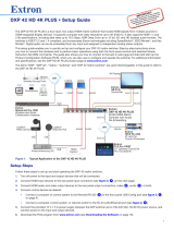
Figure 2. Application for a DXP 88 HD 4K PLUS
1
2

DXP HD 4K PLUS Series • Introduction 9
WiFi
1234
WiFi
1 234
DBS RECEIVER
DBS RECEIVER
PUSH PUSH
POWER GUIDE MENU RES 480 480p 720p 1080i 1080p
DIRECTV HD
SELECT
DIRECTV
PUSH PUSH
POWER GUIDE MENU RES 480 480p 720p 1080i 1080p
DIRECTV HD
SELECT
DIRECTV
PUSH PUSH
POWER GUIDE MENU RES 480 480p 720p 1080i 1080p
DIRECTV HD
SELECT
DIRECTV
IPCP PRO 550
OVER
21
43
LIMIT
R
IR
1234567
8
Tx
Rx
Tx
Rx
RTS
CTS
COM
IR/SERIAL
1
3
2
4
RELAYS FLEX
I/O
S
LIMIT
OVER
eBUS
SWITCHED
12 VDC
1000
LINK
ACT
21
56
3
7
4
8
21
56
3
7
4
8
QUANTUM ULTRA 610
VIDEO WALL PROCESSOR
PRIMARY POWER
OPEN
LOCK
REDUNDANT POWER
FRONT FANS
REAR FANS
STATUS
XPA 2001
LIMITER/PROTECT
SIGNAL
OVER
TEMP
1 2 3 4 5 6 7 8
9 10 11 12 13 14 15 16
INPUTS
1 2 3 4 5 6 7 8
9 10 11 12 13 14 15 16
OUTPUTS
ESCAPE AUDIOVIDEOVIEWPRESETENTER
CONTROL I/O
CONFIG
DXP HD 4K PLUS SERIES
DIGITAL CROSSPOINT MATRIX SWITCHER
Videowall
Operations Center
Audio
Extron
FF 220T
Ceiling Speakers
Extron
Quantum Ultra
Ultra high Bandwidth 4K
Videowall Processor
CPUs
HDMI
HDMI
Trafc Cam
Receivers
Satellite
Receivers
HDMI
HDMI
Audio
HDMI HDMI
Extron
DXP 1616 HD 4K PLUS
4K/60 HDMI Matrix Switcher
with Audio De-Embedding
Extron
XPA 2001-70V
Power Amplier
Codec
Laptops
Operations
Center
Ethernet
Extron
IPCP Pro 550
IP Link Pro
Control Processor
4K Displays
Ethernet/PoE
Ethernet/PoE
Ethernet/PoE
HDMI
HDMI
Extron
TLP
P
ro 7
25M
7" Wall Mount
TouchLink Pro Touchpanel
Extron
TLP Pro 725M
7" Wall Mount
TouchLink Pro Touchpanel
Extron
TLP Pro 725M
7" Wall Mount
TouchLink Pro Touchpanel
Ethernet
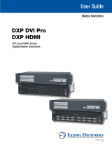
Figure 3. Application for a DXP 1616 HD 4K PLUS
3

DXP HD 4K PLUS Series • Installation 10
Installation
This section describes the rear panels of the DXP HD 4K PLUS Series matrix switchers and
provides instructions for cabling. It covers the following topics:
• Rear Panels
• Connecting to the LAN Port
• Connecting to the Remote RS-232 Port
• Connecting Power to the DXP 42 HD 4K PLUS
• Securing the HDMI Connectors Using the LockIt HDMI Cable Lacing Bracket
Rear Panels
WARNING: Remove power from the system before making any connections.
AVERTISSEMENT : Couper l’alimentation avant de faire l’installation électrique.
ATTENTION:
• Use electrostatic discharge precautions (be electrically grounded) when making
connections. Electrostatic discharge can damage equipment, although you may
not feel, see, or hear it.
• Prenez des précautions contre les décharges électrostatiques (soyez
électriquement relié à la terre) lorsque vous effectuez des connexions. Les
décharges électrostatiques peuvent endommager l’équipement, même si vous ne
pouvez pas le sentir, le voir ou l’entendre.
See figure4 (DXP 1616 and 168), figure5 (DXP 44, 84, and 88), and figure6 (DXP 42) on
the next page for diagrams of the rear panels of all models.

DXP HD 4K PLUS Series • Installation 11
DXP 168 and 1616 PLUS Rear Panel
I
I
I
E
E
E
DXP 1616 HD 4K PLUS
REMOTE
L
R
L
R
LAN
RESET
RS-232
Tx GRx
100-240V1.1A MAX
50-60Hz
INPUTS
1 2 3 4
5 6 7 8
9 10 11 12
13 14 15 16
OUTPUTS
1 2 3 4
5 6 7 8
9 10 11 12
13 14 15 16
AUDIO OUTPUTS
S/PDIF
1
2
S/PDIF
3
4
A
A
A
B
B
B
G
G
G
H
H
H
C
C
C
F
F
F
D
D
D
Figure 4. DXP 1616 PLUS HD 4K PLUS Rear Panel
NOTE: Figure 4 shows the rear panel of a DXP 1616 PLUS. The DXP 168 PLUS rear
panel is identical except that it has eight outputs instead of 16.
DXP 44, 84, and 88 PLUS Rear Panel
DXP 88 HD 4K PLUS
S/PDIF
1
2
AUDIO OUTPUTS
OUTPUTS
INPUTS
100-240V ~ --A MAX
50-60 Hz
1
5
2
6
3
7
4
8
1
5
2
6
3
7
4
8
L
R
REMOTE LAN
Tx Rx G
RESET
DXP 88 HD 4K PLUS
S/PDIF
1
2
AUDIO OUTPUTS
OUTPUTS
INPUTS
100-240V ~ 1.0A MAX
50-60 Hz
1
5
2
6
3
7
4
8
1
5
2
6
3
7
4
8
L
R
REMOTE LAN
Tx Rx G
RESET
III
FFF
E
EEG
GG
D
D
D
C
C
C
B
B
B
A
AAD
D
D
HHH
RS-232
Figure 5. DXP 88 HD 4K PLUS Rear Panel
NOTE: Figure 5 shows a DXP 88 HD 4K PLUS. The rear panels of the DXP 44 and
DXP 84 models are identical to it except for the number of inputs and outputs:
• DXP 44 HD 4K PLUS — 4 inputs and 4 outputs
• DXP 84 HD 4K PLUS — 8 inputs and 4 outputs
• DXP 88 HD 4K PLUS — 8 inputs and 8 outputs
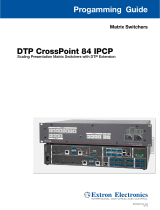
DXP 42 PLUS Rear Panel
LAN
POWER
12V
1.5A MAX
INPUTS
1
HDMI
2
HDMI
3
HDMI
4
HDMI
OUTPUTS
1
HDMI/CEC
2
HDMI/CEC
AUDIO OUTPUTS
L
3
R L
4
R
Tx
RS-232
Rx G
REMOTE
III
D
D
D
B
B
B
A
A
A
E
E
E
D
D
DF
F
F
GGG
Figure 6. DXP 42 HD 4K PLUS Rear Panel
Legend for Figures 4, 5, and 6
A
Input connectors
D
Reset button
G
Analog audio outputs
B
Output connectors
E
Remote RS-232 port
H
S/PDIF audio outputs
C
Reset and power LED
F
LAN port
I
Power connector
4
5
6

DXP HD 4K PLUS Series • Installation 12
Rear Panel Features
A
Input connectors — Connect HDMI source devices (or DVI sources with the
appropriate adapters) to these female type A HDMI input connectors.
LockIt cable lacing brackets, one for each HDMI input and output connector, are
provided with the DXP PLUS. These brackets can be used to secure the HDMI cables
to the DXP PLUS connectors to reduce stress on the HDMI connectors and prevent
signal loss due to loose cable connections.
For information on attaching the LockIt brackets, see Securing the HDMI Connectors
Using the LockIt HDMI Cable Lacing Bracket on page18).
B
Output connectors — Connect HDMI output devices (or DVI devices with the
appropriate adapters) to these female type A HDMI output connectors for buffered
video output. See Securing the HDMI Connectors Using the LockIt HDMI Cable
Lacing Bracket to attach the brackets.
C
Reset and power LED — (DXP 44, 84, 88, 168, and 1616 PLUS only) This green
LED remains lit while the DXP PLUS has power. While the Reset button (
D
) is being
pressed and held, this LED blinks every 3 seconds to indicate the level of reset that is
initiated if the button is released at that point (see Resetting on page55 for more
information).
NOTE: The factory configured passwords for all accounts on this device have been
set to the device serial number.
Performing a unit factory reset by entering an E ZQQQ } SIS command
(see page 60) or a reset mode 5 (see page 40) via the rear panel Reset button
removes the serial number passwords, leaving the unit with no password.
D
Reset button — (DXP 44, 84, 88, 168, and 1616 PLUS only) This recessed button
initiates four levels (modes) of reset on the DXP PLUS switcher. To initiate the different
reset levels, use a pointed object such as a small Philips screwdriver or a stylus to press
and hold the button while the switcher is running or while it is being powered up (see
Resetting).
E
Remote RS-232 port — Connect a host device, such as a computer or touchpanel
control, to the switcher via this 3-pole 3.5 mm captive screw connector for serial
RS-232 control.
Connect the 9-pin connector end of the RS-232 cable to the serial port of your
computer or control system (see Connecting to the Remote RS-232 Port on
page17 for more information).
F
LAN port — Connect the DXP PLUS switcher to a computer, a network switch, or
a control system via this RJ-45 connector. You can use a computer to configure and
control the networked switcher with SIS commands, the PCS configuration software, or
the HTML page that is embedded on the switcher (see Connecting to the LAN Port
on page14).
Ethernet connection indicators — The green and amber LEDs on the
LAN connector indicate the status of the Ethernet connection. The green
(link) LED indicates that the switcher is properly connected to an Ethernet
LAN. This LED should light steadily. The amber (activity) LED indicates
transmission of data packets on the RJ-45 connector. This LED should flicker as the
switcher communicates.
The default Ethernet settings are:
IP address — 192.168.254.254
Subnet mask — 255.255.0.0
Gateway address — 0.0.0.0
LAN
/