
A-10625_AB
350i
Operating Manual
Revision: AG Issue Date: August 27, 2013 Manual No.: 0-5205
Operating Features:
TRANSMIG
MULTI PROCESS
WELDING INVERTER
450i
550i

WE APPRECIATE YOUR BUSINESS!
Congratulations on your new Cigweld product. We are proud to
have you as our customer and will strive to provide you with the
best service and reliability in the industry. This product is backed
by our extensive warranty and world-wide service network. To
locate your nearest distributor or accredited service provider call
+1300 654 674, or visit us on the web at www.cigweld.com.au
This Operating Manual has been designed to instruct you on the
correct use and operation of your CIGWELD product. Your satisfaction
with this product and its safe operation is our ultimate concern.
Therefore please take the time to read the entire manual, especially
the Safety Precautions. They will help you to avoid potential hazards
that may exist when working with this product.
YOU ARE IN GOOD COMPANY!
The Brand of Choice for Contractors and Fabricators Worldwide.
CIGWELD is the Market Leading Brand of Arc Welding Products for
Victor Technologies. We are a mainline supplier to major welding
industry sectors in the Asia Pacific and emerging global markets
including; Manufacturing, Construction, Mining, Automotive,
Engineering, Rural and DIY.
We distinguish ourselves from our competition through market-
leading, dependable products that have stood the test of time. We
pride ourselves on technical innovation, competitive prices, excellent
delivery, superior customer service and technical support, together
with excellence in sales and marketing expertise.
Above all, we are committed to develop technologically advanced
products to achieve a safer working environment for industry
operators.

!
WARNINGS
Read and understand this entire Manual and your employer’s safety practices before installing,
operating, or servicing the equipment.
While the information contained in this Manual represents the Manufacturer’s best judgement,
the Manufacturer assumes no liability for its use.
Welding Power Supply
Operating Manual Number 0-5205 for:
TRANSMIG 350i Plant Part Number W1005350
TRANSMIG 350i Power Source (packed) Part Number W1005352
TRANSMIG 450i Plant with 4RT wirefeeder Part Number W1005450
TRANSMIG 450i Pro Plant with VAF4 wirefeeder Part Number W1005451
TRANSMIG 450i Power Source (packed) Part Number W1005452
TRANSMIG 550i Plant Part Number W1005550
TRANSMIG 550i Power Source (packed) Part Number W1005552
Published by:
CIGWELD Pty Ltd
71 Gower Street
Preston, Victoria, Australia, 3072
www.cigweld.com.au
Copyright 2011, 2012, 2013 by
CIGWELD
All rights reserved.
A Reproduction of this work, in whole or in part, without written permission of the
publisher is prohibited.
The publisher does not assume and hereby disclaims any liability to any party for any
loss or damage caused by any error or omission in this Manual, whether such error
results from negligence, accident, or any other cause.
Publication Date: November 21, 2011
Revision AG Date: August 27, 2013
Record the following information for Warranty purposes:
Where Purchased: ____________________________________
Purchase Date: ____________________________________
Equipment Serial #: ____________________________________

TABLE OF CONTENTS
SECTION 1:
ARC WELDING SAFETY INSTRUCTIONS AND WARNINGS ..................................... 1-1
1.01 Arc Welding Hazards ....................................................................................... 1-1
1.02 Principal Safety Standards .............................................................................. 1-5
1.03 Declaration of Conformity ............................................................................... 1-6
SECTION 2:
INTRODUCTION ..................................................................................... 2-1
2.01 How To Use This Manual ................................................................................ 2-1
2.02 Equipment Identification ................................................................................. 2-1
2.03 Receipt Of Equipment ..................................................................................... 2-1
2.04 Symbol Chart .................................................................................................. 2-2
2.05 Description ..................................................................................................... 2-3
2.06 User Responsibility ......................................................................................... 2-3
2.07 Transporting Methods ..................................................................................... 2-3
2.08 Packaged Items .............................................................................................. 2-4
2.09 Duty Cycle ....................................................................................................... 2-5
2.10 Specifications ................................................................................................. 2-6
2.11 Gouging Specifications (Transmig 550i only) ................................................. 2-7
2.12 Optional Accessories ...................................................................................... 2-8
SECTION 3:
INSTALLATION, OPERATION AND SETUP ........................................................ 3-1
3.01 Environment ................................................................................................... 3-1
3.02 Location .......................................................................................................... 3-1
3.03 Ventilation ....................................................................................................... 3-1
3.04 Mains Supply Voltage Requirements .............................................................. 3-1
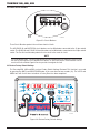
3.05 Electromagnetic Compatibility ........................................................................ 3-1
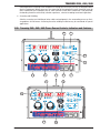
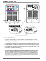
3.06 Transmig 350i, 450i, 550i Power Source Controls, Indicators and Features .. 3-3
3.07 Shielding Gas Regulator Operating Instructions ........................................... 3-15
3.08 Setup for MIG (GMAW) Welding with Gas Shielded Mig Wire ...................... 3-17
3.09 Setup for MIG (GMAW) Welding with Gasless Mig Wire .............................. 3-20
3.10 Setup for TIG (GTAW) Welding With Gas Shielding ...................................... 3-22
3.11 Setup for STICK (MMAW) Welding ............................................................. 3-24
3.12 Setup for GOUGING (Transmig 550i only) .................................................... 3-25
SECTION 4:
BASIC WELDING GUIDE ............................................................................ 4-1
4.01 MIG (GMAW/FCAW) Basic Welding Technique ............................................... 4-1
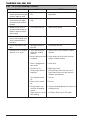
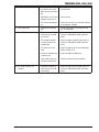
4.02 MIG (GMAW/FCAW) Welding Troubleshooting ............................................... 4-7
4.03 Stick (MMAW) Basic Welding Technique ...................................................... 4-10
4.04 Stick (MMAW) Welding Troubleshooting ...................................................... 4-21
4.05 TIG (GTAW) Basic Welding Technique .......................................................... 4-23
4.06 TIG (GTAW) Welding Problems ..................................................................... 4-25

TABLE OF CONTENTS
SECTION 5:
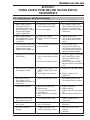
POWER SOURCE PROBLEMS AND ROUTINE SERVICE REQUIREMENTS .................... 5-1
5.01 Power Source / Wirefeeder Problems ............................................................. 5-1
5.02 Routine Service and Calibration Requirements ............................................... 5-2
5.03 Cleaning the Welding Power Source ............................................................... 5-4
5.04 Cleaning the Feed Rolls ................................................................................... 5-4
SECTION 6:
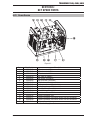
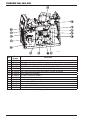
KEY SPARE PARTS ................................................................................... 6-1
6.01 Power Source ................................................................................................. 6-1
SECTION 7:
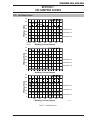
VOLT/AMPERE CURVES ............................................................................. 7-1
7.01 Volt/Amp Curves ............................................................................................. 7-1
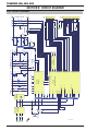
SECTION 8: CIRCUIT DIAGRAM .......................................................................... 8-1
8.01 Circuit Diagram ..................................................................................................... 8-1
CIGWELD - LIMITED WARRANTY TERMS
TERMS OF WARRANTY – JULY 2011
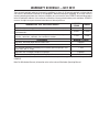
WARRANTY SCHEDULE – JULY 2011
GLOBAL CUSTOMER SERVICE CONTACT INFORMATION


TRANSMIG 350i, 450i, 550i
Manual 0-5205 1-1 GENERAL INFORMATION
1.01 ARC WELDING HAZARDS
WARNING
ELECTRIC SHOCK can kill.
Touching live electrical parts can cause
fatal shocks or severe burns. The electrode
and work circuit is electrically live when-
ever the output is on. The input power cir-
cuit and machine internal circuits are also
live when power is on. In semiautomatic
or automatic wire welding, the wire, wire
reel, drive roll housing, and all metal parts
touching the welding wire are electrically
live. Incorrectly installed or improperly
grounded equipment is a hazard.
1. Do not touch live electrical parts.
2. Wear dry, hole-free insulating gloves and body
protection.
3. Insulate yourself from work and ground using dry
insulating mats or covers.
4. Disconnect input power or stop engine before
installing or servicing this equipment. Lock input
power disconnect switch open, or remove line
fuses so power cannot be turned on acciden-
tally.
5. Properly install and ground this equipment accord-
ing to its Owner’s Manual and national, state, and
local codes.
6. Turn off all equipment when not in use. Disconnect
power to equipment if it will be left unattended or
out of service.
7. Use fully insulated electrode holders. Never dip
holder in water to cool it or lay it down on the
ground or the work surface. Do not touch holders
connected to two welding machines at the same
time or touch other people with the holder or
electrode.
8. Do not use worn, damaged, undersized, or poorly
spliced cables.
9. Do not wrap cables around your body.
10. Ground the workpiece to a good electrical (earth)
ground.
11. Do not touch electrode while in contact with the
work (ground) circuit.
12. Use only well-maintained equipment. Repair or
replace damaged parts at once.
13. In confined spaces or damp locations, do not use a
welder with AC output unless it is equipped with a
voltage reducer. Use equipment with DC output.
14. Wear a safety harness to prevent falling if working
above floor level.
15. Keep all panels and covers securely in place.
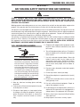
SECTION 1:
ARC WELDING SAFETY INSTRUCTIONS AND WARNINGS
!
WARNING
PROTECT YOURSELF AND OTHERS FROM POSSIBLE SERIOUS INJURY OR DEATH. KEEP CHILDREN
AWAY. PACEMAKER WEARERS KEEP AWAY UNTIL CONSULTING YOUR DOCTOR. DO NOT LOSE THESE
INSTRUCTIONS. READ OPERATING/INSTRUCTION MANUAL BEFORE INSTALLING, OPERATING OR
SERVICING THIS EQUIPMENT.
Welding products and welding processes can cause serious injury or death, or damage to other equipment or
property, if the operator does not strictly observe all safety rules and take precautionary actions.
Safe practices have developed from past experience in the use of welding and cutting. These practices must be
learned through study and training before using this equipment. Some of these practices apply to equipment
connected to power lines; other practices apply to engine driven equipment. Anyone not having extensive
training in welding and cutting practices should not attempt to weld.
Safe practices are outlined in the Australian Standard AS1674.2-2007 entitled: Safety in welding and allied
processes Part 2: Electrical. This publication and other guides to what you should learn before operating
this equipment are listed at the end of these safety precautions. HAVE ALL INSTALLATION, OPERATION,
MAINTENANCE, AND REPAIR WORK PERFORMED ONLY BY QUALIFIED PEOPLE.

TRANSMIG 350i, 450i, 550i
GENERAL INFORMATION 1-2 Manual 0-5205
WARNING
ARC RAYS can burn eyes and skin; NOISE
can damage hearing.
Arc rays from the welding process produce
intense heat and strong ultraviolet rays
that can burn eyes and skin. Noise from
some processes can damage hearing.
1. Use a Welding Helmet or Welding Faceshield fitted
with a proper shade of filter (see ANSI Z49.1 and
AS 1674 listed in Safety Standards) to protect your
face and eyes when welding or watching.
2. Wear approved safety glasses. Side shields recom-
mended.
3. Use protective screens or barriers to protect others
from flash and glare; warn others not to watch the
arc.
4. Wear protective clothing made from durable,
flame-resistant material (wool and leather) and
foot protection.
5. Use approved ear plugs or ear muffs if noise level
is high.
6. Never wear contact lenses while welding.
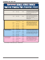
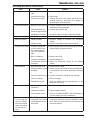
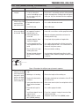
Recommended Protective Filters for Electric Welding
Description of Process
Approximate Range of
Welding Current in Amps
Minimum Shade Number of
Filter(s)
Manual Metal Arc Welding - covered
electrodes (MMAW)
Less than or equal to 100 8
100 to 200 10
200 to 300 11
300 to 400 12
Greater than 400 13
Gas Metal Arc Welding (GMAW)
(MIG) other than Aluminium and
Stainless Steel
Less than or equal to 150 10
150 to 250 11
250 to 300 12
300 to 400 13
Greater than 400 14
Gas Metal Arc Welding (GMAW)
(MIG) Aluminium and Stainless Steel
Less than or equal to 250 12
250 to 350 13
Gas Tungsten Arc Welding (GTAW)
(TIG)
Less than or equal to 100 10
100 to 200 11
200 to 250 12
250 to 350 13
Greater than 350 14
Flux-cored Arc Welding (FCAW) -with
or without shielding gas.
Less than or equal to 300 11
300 to 400 12
400 to 500 13
Greater than 500 14
Air - Arc Gouging Less than or equal to 400 12
Plasma - Arc Cutting
50 to 100 10
100 to 400 12
400 to 800 14
Plasma - Arc Spraying
—
15
Plasma - Arc Welding
Less than or equal to 20 8
20 to 100 10
100 to 400 12
400 to 800 14
Submerged - Arc Welding
—
2(5)
Resistance Welding
—
Safety Spectacles or eye
shield
Refer to standard AS/NZS 1338.1:1992 for comprehensive information regarding the above table.

TRANSMIG 350i, 450i, 550i
Manual 0-5205 1-3 GENERAL INFORMATION
WARNING
FUMES AND GASES can be hazardous to
your health.
Welding produces fumes and gases.
Breathing these fumes and gases can be
hazardous to your health.
1. Keep your head out of the fumes. Do not breath
the fumes.
2. If inside, ventilate the area and/or use exhaust at
the arc to remove welding fumes and gases.
3. If ventilation is poor, use an approved air-supplied
respirator.
4. Read the Material Safety Data Sheets (MSDSs)
and the manufacturer’s instruction for metals,
consumables, coatings, and cleaners.
5. Work in a confined space only if it is well venti-
lated, or while wearing an air-supplied respirator.
Shielding gases used for welding can displace air
causing injury or death. Be sure the breathing air
is safe.
6. Do not weld in locations near degreasing, cleaning,
or spraying operations. The heat and rays of the
arc can react with vapours to form highly toxic
and irritating gases.
7. Do not weld on coated metals, such as galvanized,
lead, or cadmium plated steel, unless the coating
is removed from the weld area, the area is well
ventilated, and if necessary, while wearing an air-
supplied respirator. The coatings and any metals
containing these elements can give off toxic fumes
if welded.
WARNING
WELDING can cause fire or explosion.
Sparks and spatter fly off from the welding
arc. The flying sparks and hot metal, weld
spatter, hot workpiece, and hot equipment
can cause fires and burns. Accidental con
-
tact of electrode or welding wire to metal
objects can cause sparks, overheating,
or fire.
1. Protect yourself and others from flying sparks and
hot metal.
2. Do not weld where flying sparks can strike flam-
mable material.
3. Remove all flammables within 35 ft (10.7 m) of the
welding arc. If this is not possible, tightly cover
them with approved covers.
4. Be alert that welding sparks and hot materials from
welding can easily go through small cracks and
openings to adjacent areas.
5. Watch for fire, and keep a fire extinguisher
nearby.
6. Be aware that welding on a ceiling, floor, bulkhead,
or partition can cause fire on the hidden side.
7. Do not weld on closed containers such as tanks
or drums.
8. Connect work cable to the work as close to the
welding area as practical to prevent welding cur-
rent from travelling long, possibly unknown paths
and causing electric shock and fire hazards.
9. Do not use welder to thaw frozen pipes.
10. Remove stick electrode from holder or cut off
welding wire at contact tip when not in use.
WARNING
FLYING SPARKS AND HOT METAL can
cause injury.
Chipping and grinding cause flying metal.
As welds cool, they can throw off slag.
1. Wear approved face shield or safety goggles. Side
shields recommended.
2. Wear proper body protection to protect skin.
WARNING
CYLINDERS can explode if damaged.
Shielding gas cylinders contain gas under
high pressure. If damaged, a cylinder can
explode. Since gas cylinders are normally
part of the welding process, be sure to
treat them carefully.
1. Protect compressed gas cylinders from excessive
heat, mechanical shocks, and arcs.
2. Install and secure cylinders in an upright position
by chaining them to a stationary support or equip-
ment cylinder rack to prevent falling or tipping.
3. Keep cylinders away from any welding or other
electrical circuits.
4. Never allow a welding electrode to touch any
cylinder.

TRANSMIG 350i, 450i, 550i
GENERAL INFORMATION 1-4 Manual 0-5205
5. Use only correct shielding gas cylinders,
regulators, hoses, and fittings designed for the
specific application; maintain them and associated
parts in good condition.
6. Turn face away from valve outlet when opening
cylinder valve.
7. Keep protective cap in place over valve except
when cylinder is in use or connected for use.
8. Read and follow instructions on compressed
gas cylinders, associated equipment, and CGA
publication P-1 listed in Safety Standards.
WARNING
MOVING PARTS can cause injury.
Moving parts, such as fans, rotors, and belts can cut
fingers and hands and catch loose clothing.
1. Keep all doors, panels, covers, and guards closed
and securely in place.
2. Stop engine before installing or connecting unit.
3. Have only qualified people remove guards or
covers for maintenance and troubleshooting as
necessary.
4. To prevent accidental starting during servicing,
disconnect negative (-) battery cable from bat-
tery.
5. Keep hands, hair, loose clothing, and tools away
from moving parts.
6. Reinstall panels or guards and close doors when
servicing is finished and before starting engine.
!
WARNING
This product, when used for welding or
cutting, produces fumes or gases which
contain chemicals know to the State of
California to cause birth defects and, in
some cases, cancer. (California Health &
Safety code Sec. 25249.5 et seq.)
NOTE
Considerations About Welding And The
Effects of Low Frequency Electric and
Magnetic Fields
The following is a quotation from the General Con-
clusions Section of the U.S. Congress, Office of
Technology Assessment, Biological Effects of Power
Frequency Electric & Magnetic Fields - Background
Paper, OTA-BP-E-63 (Washington, DC: U.S. Govern-
ment Printing Office, May 1989): “...there is now
a very large volume of scientific findings based on
experiments at the cellular level and from studies
with animals and people which clearly establish that
low frequency magnetic fields and interact with, and
produce changes in, biological systems. While most
of this work is of very high quality, the results are
complex. Current scientific understanding does not
yet allow us to interpret the evidence in a single coher-
ent framework. Even more frustrating, it does not yet
allow us to draw definite conclusions about questions
of possible risk or to offer clear science-based advice
on strategies to minimize or avoid potential risks.”
To reduce magnetic fields in the workplace, use the
following procedures.
1. Keep cables close together by twisting or taping
them.
2. Arrange cables to one side and away from the
operator.
3. Do not coil or drape cable around the body.
4. Keep welding power source and cables as far away
from body as practical.
ABOUT PACEMAKERS:
The above procedures are among those
also normally recommended for pace-
maker wearers. Consult your doctor for
complete information.

TRANSMIG 350i, 450i, 550i
Manual 0-5205 1-5 GENERAL INFORMATION
1.02 PRINCIPAL SAFETY STANDARDS
Safety in Welding and Cutting, ANSI Standard Z49.1, from American Welding Society, 550 N.W. LeJeune Rd.,
Miami, FL 33126.
Safety and Health Standards, OSHA 29 CFR 1910, from Superintendent of Documents, U.S. Government
Printing Office, Washington, D.C. 20402.
Recommended Safe Practices for the Preparation for Welding and Cutting of Containers That Have Held
Hazardous Substances, American Welding Society Standard AWS F4.1, from American Welding Society, 550
N.W. LeJeune Rd., Miami, FL 33126.
National Electrical Code, NFPA Standard 70, from National Fire Protection Association, Batterymarch Park,
Quincy, MA 02269.
Safe Handling of Compressed Gases in Cylinders, CGA Pamphlet P-1, from Compressed Gas Association,
1235 Jefferson Davis Highway, Suite 501, Arlington, VA 22202.
Code for Safety in Welding and Cutting, CSA Standard W117.2, from Canadian Standards Association, Stan-
dards Sales, 178 Rexdale Boulevard, Rexdale, Ontario, Canada M9W 1R3.
Safe Practices for Occupation and Educational Eye and Face Protection, ANSI Standard Z87.1, from American
National Standards Institute, 1430 Broadway, New York, NY 10018.
Cutting and Welding Processes, NFPA Standard 51B, from National Fire Protection Association, Batterymarch
Park, Quincy, MA 02269.
Safety in welding and allied processes Part 1: Fire Precautions, AS 1674.1-1997 from SAI Global Limited,
www.saiglobal.com.
Safety in welding and allied processes Part 2: Electrical, AS 1674.2-2007 from SAI Global Limited, www.
saiglobal.com.
Filters for eye protectors - Filters for protection against radiation generated in welding and allied operations
AS/NZS 1338.1:1992 from SAI Global Limited, www.saiglobal.com.

TRANSMIG 350i, 450i, 550i
GENERAL INFORMATION 1-6 Manual 0-5205
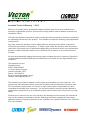
1.03 DECLARATION OF CONFORMITY
Manufacturer and Merchandiser of Quality Consumables and Equipment : CIGWELD
Address: 71 Gower St, Preston
Victoria 3072
Australia
Description of equipment: Welding Equipment: TRANSMIG 350i, 450i, 550i MULTI PROCESS INVERTER Power
Source and associated accessories.
* Serial numbers are unique with each individual piece of equipment and details description, parts used to
manufacture a unit and date of manufacture.
* The equipment conforms to all applicable aspects and regulations of the ‘Low Voltage Directive’ (2006/95
EC) and to the National legislation for the enforcement of the Directive.
National Standard and Technical Specifications
The product is designed and manufactured to a number of standards and technical requirements among them
are:
* AS 60974.10/IEC 60974-10 EMC Directive applicable to arc welding equipment - generic emissions and
regulations.
* AS 60974.1/IEC 60974-1 applicable to welding equipment and associated accessories.
* AS 1674 Safety in welding and allied processes
* Extensive product design verification is conducted at the manufacturing facility as part of the routine de-
sign and manufacturing process, to ensure the product is safe and performs as specified. Rigorous testing is
incorporated into the manufacturing process to ensure the manufactured product meets or exceeds all design
specifications.
CIGWELD has been manufacturing and merchandising an extensive equipment range with superior performance,
ultra safe operation and world class quality for more than 30 years and will continue to achieve excellence.

TRANSMIG 350i, 450i, 550i
Manual 0-5205 2-1 INTRODUCTION
SECTION 2:
INTRODUCTION
2.02 Equipment Identification
The unit’s identification number (specification or
part number), model, and serial number usually ap-
pear on a nameplate attached to the control panel. In
some cases, the nameplate may be attached to the
rear panel. Equipment which does not have a control
panel such as gun and cable assemblies is identified
only by the specification or part number printed on
the shipping container. Record these numbers on the
bottom of page i for future reference.
2.03 Receipt Of Equipment
When you receive the equipment, check it against the
invoice to make sure it is complete and inspect the
equipment for possible damage due to shipping. If
there is any damage, notify the carrier immediately to
file a claim. Furnish complete information concerning
damage claims or shipping errors to the location in
your area listed in the inside back cover of this manual.
Include all equipment identification numbers as
described above along with a full description of the
parts in error.
Move the equipment to the installation site before
un-crating the unit. Use care to avoid damaging the
equipment when using bars, hammers, etc., to un-
crate the unit.
2.01 How To Use This Manual
To ensure safe operation, read the entire manual,
including the chapter on safety instructions and
warnings.
Throughout this manual, the words WARNING,
CAUTION, and NOTE may appear. Pay particular at-
tention to the information provided under these head-
ings. These special annotations are easily recognized
as follows:
!
WARNING
A WARNING gives information regarding
possible personal injury.
CAUTION
A CAUTION refers to possible equipment
damage.
NOTE
A NOTE offers helpful information con
-
cerning certain operating procedures.
Additional copies of this manual may be purchased by
contacting Cigweld at the address and phone number
for your location listed in the inside back cover of this
manual. Include the Owner’s Manual number and
equipment identification numbers.

TRANSMIG 350i, 450i, 550i
INTRODUCTION 2-2 Manual 0-5205
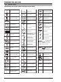
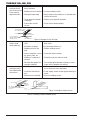
2.04 Symbol Chart
Note that only some of these symbols will appear on your model.
Gas Tungsten Arc
Welding (GTAW)
Air Carbon Arc
Cutting (CAC-A)
Constant Current
Constant Voltage
Or Constant Potential
High Te mperature
Fault Indication
Arc Force
Touch Start (GTAW)
Variable Inductance
Voltage Input
Single Phase
Three Phase
Three Phase Static
Frequency Converter-
Transformer-Rectifier
Dangerous Voltage
Off
On
Panel/Local
Shielded Metal
Arc Welding (SMAW)
Gas Metal Arc
Welding (GMAW)
Increase/Decrease
Circuit Breaker
AC Auxiliary Power
Remote
Duty Cycle
Percentage
Amperage
Voltage
Hertz (cycles/sec)
Frequency
Negative
Positive
Direct Current (DC)
Protective Earth
(Ground)
Line
Line Connection
Auxiliary Power
Receptacle Rating-
Auxiliary Power
Art # A-04937
115V 15A
t
t1
t2
%
X
IPM
MPM
t
V
Fuse
Wire Feed Function
Wire Feed Towards
Workpiece With
Output Voltage Off.
Preflow Time
Postflow Time
Spot Time
Spot Weld Mode
Continuous Weld
Mode
Press to initiate wirefeed and
welding, release to stop.
Purging Of Gas
Inches Per Minute
Meters Per Minute
Disturbance In
Ground System
Welding Gun
Burnback Time
Press and hold for preflow, release
to start arc. Press to stop arc, and
hold for preflow.
4 Step Trigger
Operation
2 Step Trigger
Operation

TRANSMIG 350i, 450i, 550i
Manual 0-5205 2-3 INTRODUCTION
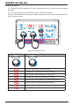
2.05 Description
The Cigweld Transmig 350i, 450i and 550i are three
phase multi process welding inverters that are capable
of performing GMAW/FCAW (MIG), MMAW (Stick)
and GTAW (Lift TIG) welding processes. The unit is
equipped with an integrated voltage reduction device
(VRD applicable in stick mode only), digital voltage
and amperage meters, and a host of other features
in order to fully satisfy the broad operating needs of
the modern welding professional. The unit is also
fully compliant to Australian Standard AS 60974.1
and IEC 60974.1.
The Transmig 350i, 450i and 550i provide excellent
welding performance across a broad range of ap-
plications when used with the correct welding con-
sumables and procedures. The following instructions
detail how to correctly and safely set up the machine
and give guidelines on gaining the best efficiency and
quality from the Power Source. Please read these
instructions thoroughly before using the unit.
2.06 User Responsibility
This equipment will perform as per the information
contained herein when installed, operated, maintained
and repaired in accordance with the instructions pro-
vided. This equipment must be checked periodically.
Defective equipment (including welding leads) should
not be used. Parts that are broken, missing, plainly
worn, distorted or contaminated, should be replaced
immediately. Should such repairs or replacements
become necessary, it is recommended that such re-
pairs be carried out by appropriately qualified persons
approved by CIGWELD. Advice in this regard can
be obtained by contacting an Accredited CIGWELD
Distributor.
This equipment or any of its parts should not be al-
tered from standard specification without prior written
approval of CIGWELD. The user of this equipment
shall have the sole responsibility for any malfunction
which results from improper use or unauthorized
modification from standard specification, faulty
maintenance, damage or improper repair by anyone
other than appropriately qualified persons approved
by CIGWELD.
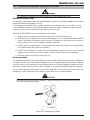
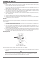
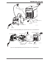
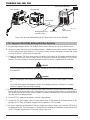
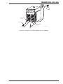
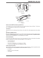
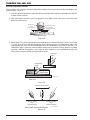
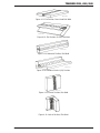
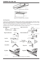
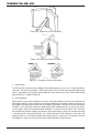
2.07 Transporting Methods
This unit is equipped with a handle for carrying
purposes.
WARNING
ELECTRIC SHOCK can kill. DO NOT TOUCH
live electrical parts. Disconnect input
power conductors from de-energized
supply line before moving the welding
power source.
!
WARNING
FALLING EQUIPMENT can cause serious
personal injury and equipment damage.
Lift unit with handle or lifting lug on top of case.
Use handcart or similar device of adequate capacity.
If using a fork lift vehicle, place and secure unit on a
proper skid before transporting.

TRANSMIG 350i, 450i, 550i
INTRODUCTION 2-4 Manual 0-5205
2.08 Packaged Items
Transmig 350i Plant (Part No. W1005350)
• Transmig 350i Inverter Power Source
• Transmig 4RT wirefeeder, 10 pin
• 8m Interconnection lead, 10 pin
• Tweco Professional No.4 Mig Torch Euro, 3.6m
• Comet Professional Argon regulator/owmeter
• Feed roll: 0.9/1.2mm V groove (tted)
• Electrode holder with 5m lead
• Work clamp with 5m lead
• Heavy Duty Trolley with inbuilt cylinder carrier
• Operating Manual
Transmig 350i Power Source (Part No. W1005352)
• Transmig 350i inverter Power Source
• Operating Manual
Transmig 450i Plant (Part No. W1005450)
• Transmig 450i Inverter Power Source
• Transmig 4RT wirefeeder, 10 pin
• 8m Interconnection lead, 10 pin
• Tweco Professional No. 4 Mig Torch Euro, 3.6m
• Comet Professional Argon regulator/owmeter
• Feed roll: 0.9/1.2mm V groove (tted)
• Electrode holder with 8m lead
• Work clamp with 8m lead
• Heavy Duty Trolley with inbuilt cylinder carrier
• Operating Manual
Transmig 450i Pro Plant (Part No. W1005451)
• Transmig 450i Inverter Power Source
• Transmig VAF4 wirefeeder, 19 pin
• 8m Interconnection lead, 19 pin
• Spool Cover Kit
• Tweco Professional Supra XT Mig Torch 4m, Euro
• Comet Professional Argon regulator/owmeter
• Feed roll: 0.9/1.2mm V groove (tted)
• Electrode holder with 8m lead
• Work clamp with 8m lead
• Heavy Duty Trolley with inbuilt cylinder carrier
• Operating Manual
Transmig 450i Power Source (Part No. W1005452)
• Transmig 450i inverter Power Source
• Operating Manual
Transmig 550i Plant (Part No. W1005550)
• Transmig 550i Inverter Power Source
• Transmig VA4000 wirefeeder with 15m intercon-
nection lead
• Tweco Professional Supra XT Mig Torch
• Comet Professional Argon regulator/owmeter
• Feed roll: 1.3/1.6mm V groove (tted)
• Electrode holder with 8m lead
• Work clamp with 8m lead
• Heavy Duty Trolley with inbuilt cylinder carrier
• Operating Manual
Transmig 550i Power Source (Part No. W1005552)
• Transmig 550i inverter Power Source
• Operating Manual

TRANSMIG 350i, 450i, 550i
Manual 0-5205 2-5 INTRODUCTION
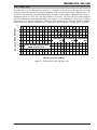
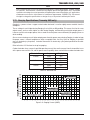
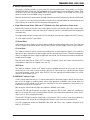
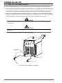
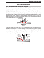
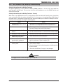
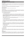
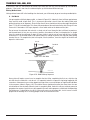
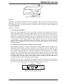
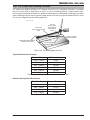
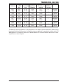
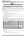
2.09 Duty Cycle
The rated duty cycle of a Welding Power Source, is a statement of the time it may be operated at its rated
welding current output without exceeding the temperature limits of the insulation of the component parts. To
explain the 10 minute duty cycle period the following example is used. Suppose a Welding Power Source is
designed to operate at a 60% duty cycle, 550 amperes at 41.5 volts. This means that it has been designed
and built to provide the rated amperage (550A) for 6 minutes, i.e. arc welding time, out of every 10 minute
period (60% of 10 minutes is 6minutes). During the other 4minutes of the 10 minute period the Welding
Power Source must idle and allowed to cool. The thermal cut out will operate if the duty cycle is exceeded.
25 50 75 100 125 150 175 200 225 250 275 300 325 350 375 400 425 450 475 500 525 550
TRANSMIG
550i
TRANSMIG
450i
TRANSMIG
350i
Welding Current (AMPS)
SAFE OPERATING REGION
(MIG, STICK & TIG )
0
0
10
20
30
40
60
70
50
80
100
90
Duty Cycle (PERCENTAGE)
A-10626
Figure 2-1: Transmig 350i, 450i, 550i Duty Cycle

TRANSMIG 350i, 450i, 550i
INTRODUCTION 2-6 Manual 0-5205
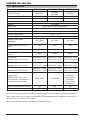
2.10 Specifications
Description TRANSMIG 350i TRANSMIG 450i TRANSMIG 550i
Plant Part Number W1005350
W1005450
W1005451
W1005550
Power Source (Packed)Part Number W1005352 W1005452 W1005552
Power Source Mass 65 kg 72 kg 72 kg
Power Source Dimensions H 580mm x W 350mm x D 640mm
Cooling Fan Cooled
Welder Type Multi Process Inverter Power Source
Applicable Standards AS 60974.1-2006 / IEC 60974-1
Number of Phases 3
Nominal Supply Voltage 415V +/- 15%
Nominal Supply Frequency 50/60Hz
Welding Current Range
(MIG Mode)
40 – 350A 40 – 450A 40 – 550A
Effective Input Current (I 1eff)
(note1)
18A 25A 32A
Maximum Input Current (I1max) 25A 35A 47A
Three Phase Generator Requirement
(note 3)
18kVA 25kVA 35kVA
MIG (GMAW)
Welding Output, 40ºC, 10 min.
350A @ 60%, 31.5V
270A @ 100%, 27.5V
450A @ 60%, 36.5V
350A @ 100%, 31.5V
550A @ 60%, 41.5V
420A @ 100%, 35.0V
STICK (MMAW)
Welding Output, 40ºC, 10 min.
350A @ 60%, 34.0V
270A @ 100%, 30.8V
450A @ 60%, 38.0V
350A @ 100%, 34.0V
550A @ 60%, 42.0V
420A @ 100%, 36.8V
TIG (GTAW)
Welding Output, 40ºC, 10 min.
350A @ 60%, 24.0V
270A @ 100%, 20.8V
450A @ 60%, 28.0V
350A @ 100%, 24.0V
550A @ 60%, 32.0V
420A @ 100%, 26.8V
Gouging (CAG)
Welding Output, 40ºC, 3 min.
Note: Gouging is specified over a 3
minute duty cycle period only.
Not Available Not Available
6.5mm Carbon
400A@63%
8.0mm Carbon
450A@54%
9.5mm Carbon
550A@35%
Open circuit voltage (VRD inactive) 72V 84V 84V
Protection Class IP23S IP23S IP23S
Table 2-1: Power Source Specification
Note 1: The Effective Input Current should be used for the determination of cable size & supply requirements.
Note 2: Motor start fuses or thermal circuit breakers are recommended for this application. Check local re-
quirements for your situation in this regard.
Note 3: Generator Requirements at the Maximum Output Duty Cycle.

TRANSMIG 350i, 450i, 550i
Manual 0-5205 2-7 INTRODUCTION
NOTE
Due to variations that can occur in manufactured products, claimed performance, voltages, ratings,
all capacities, measurements, dimensions and weights quoted are approximate only. Achievable
capacities and ratings in use and operation will depend upon correct installation, use, applications,
maintenance and service. In the interest of continuous improvement, CIGWELD Pty, Ltd reserves
the right to change the specifications or design of any of its products without prior notice.
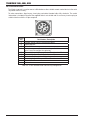
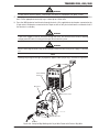
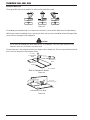
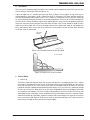
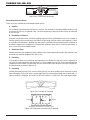
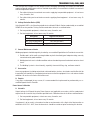
2.11 Gouging Specifications (Transmig 550i only)
Gouging is a process where a copper coated carbon electrode is used to rapidly remove material from the
workpiece.
The arc voltage is much higher during Gouging, than in Stick, or Mig welding. This means, that for the same
output current, we have much higher arc volts during Gouging, and therefore much higher output power. It
is because of this extra output power, that we need to rate the power source differently for gouging, than we
do for welding.
Also as we are drawing a much higher output power from the power source during Gouging, in order to keep
the power source's internal temperatures within acceptable limits, the Duty Cycle for Gouging is specified
over a 3 minute duty cycle period, instead of the normal 10 minute duty cycle period specified for the weld-
ing processes.
Refer to Section 3.12 for how to set up for gouging.
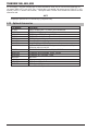
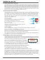
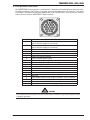
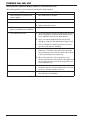
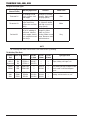
Carbon electrodes have a range of specified operating current. Here are the normal sizes that would be in use
with a power source of this size, and the power source capability when used with these carbon electrode sizes
Electrode Size Amps Duty Cycle
6.5mm 300A 90%
400A 63%
8.0mm 350A 70%
450A 54%
9.5mm 450A 50%
550A 35%
Table 2-2: Electrode Size
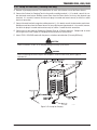
A-11481
Figure 2-2: Gouging Current (AMPS)

TRANSMIG 350i, 450i, 550i
INTRODUCTION 2-8 Manual 0-5205
As an example, if we were Gouging with an 8mm electrode at 400A, we can see from the graph that we
can expect 400A at 57% duty cycle. For a 3 minute duty cycle period, this means our arc time is 57% of 3
minutes, which is 1 minute & 40 seconds, during the other 1 minute & 20 seconds the machine must be
allowed to cool.
NOTE
Gouging is specified for a 3 minute duty cycle period only.
2.12 Optional Accessories
Part Number Description
717201 TWECO #4 Mig Torch, 3.6 metre Tweco connection
717335 TWECO #4 Mig Torch, 4.5 metre Tweco connection
SE4004M16 TWECO Supra XT Mig Torch (4.0M) Tweco connection
717211 TWECO #5 torch, 3.6 metre Tweco connection
717212 TWECO #5 torch, 4.5 metre Tweco connection
W4015500 Heavy Duty Transmig Trolley with inbuilt cylinder carrier
W4015600 Heavy Duty Transmig Roll Cage
W4014602 Tig Torch 26V, Flex neck, 4m lead, gas valve, 3m gas hose, 10 pin
connector and accessory kit.
706954 TRANSMIG VA4000 wirefeeder, 19 pin, 110VAC
W3000700 TRANSMIG VAF4 wirefeeder, 19 pin, 110VAC
W3000600 TRANSMIG 4RT wirefeeder, 10 pin
WSPLIER MIG Pliers
646265 Weld measurement gauge
W7005358 10 Pin Control Plug
7977877 19 Pin Control Plug
Table 2-3: Optional Accessories
Page is loading ...
Page is loading ...
Page is loading ...
Page is loading ...
Page is loading ...
Page is loading ...
Page is loading ...
Page is loading ...
Page is loading ...
Page is loading ...
Page is loading ...
Page is loading ...
Page is loading ...
Page is loading ...
Page is loading ...
Page is loading ...
Page is loading ...
Page is loading ...
Page is loading ...
Page is loading ...
Page is loading ...
Page is loading ...
Page is loading ...
Page is loading ...
Page is loading ...
Page is loading ...
Page is loading ...
Page is loading ...
Page is loading ...
Page is loading ...
Page is loading ...
Page is loading ...
Page is loading ...
Page is loading ...
Page is loading ...
Page is loading ...
Page is loading ...
Page is loading ...
Page is loading ...
Page is loading ...
Page is loading ...
Page is loading ...
Page is loading ...
Page is loading ...
Page is loading ...
Page is loading ...
Page is loading ...
Page is loading ...
Page is loading ...
Page is loading ...
Page is loading ...
Page is loading ...
Page is loading ...
Page is loading ...
Page is loading ...
Page is loading ...
Page is loading ...
Page is loading ...
Page is loading ...
Page is loading ...
Page is loading ...
Page is loading ...
Page is loading ...
Page is loading ...
Page is loading ...
Page is loading ...
Page is loading ...
Page is loading ...
-
 1
1
-
 2
2
-
 3
3
-
 4
4
-
 5
5
-
 6
6
-
 7
7
-
 8
8
-
 9
9
-
 10
10
-
 11
11
-
 12
12
-
 13
13
-
 14
14
-
 15
15
-
 16
16
-
 17
17
-
 18
18
-
 19
19
-
 20
20
-
 21
21
-
 22
22
-
 23
23
-
 24
24
-
 25
25
-
 26
26
-
 27
27
-
 28
28
-
 29
29
-
 30
30
-
 31
31
-
 32
32
-
 33
33
-
 34
34
-
 35
35
-
 36
36
-
 37
37
-
 38
38
-
 39
39
-
 40
40
-
 41
41
-
 42
42
-
 43
43
-
 44
44
-
 45
45
-
 46
46
-
 47
47
-
 48
48
-
 49
49
-
 50
50
-
 51
51
-
 52
52
-
 53
53
-
 54
54
-
 55
55
-
 56
56
-
 57
57
-
 58
58
-
 59
59
-
 60
60
-
 61
61
-
 62
62
-
 63
63
-
 64
64
-
 65
65
-
 66
66
-
 67
67
-
 68
68
-
 69
69
-
 70
70
-
 71
71
-
 72
72
-
 73
73
-
 74
74
-
 75
75
-
 76
76
-
 77
77
-
 78
78
-
 79
79
-
 80
80
-
 81
81
-
 82
82
-
 83
83
-
 84
84
-
 85
85
-
 86
86
-
 87
87
-
 88
88


Ask a question and I''ll find the answer in the document
Finding information in a document is now easier with AI
Related papers
-
CIGWELD 450i User manual
-
-
ESAB 400 i TRANSMIG® Inverter Arc Welder User manual
-
-
ESAB Transmig 350i, 450i, 550i Troubleshooting instruction
-
CIGWELD WeldSkill 155 Operating instructions
-
-
-
-
Other documents
-
 HIT Welding 802030 User guide
-
-
GYS CARMIG Owner's manual
-
-
Matco Tools M148 User manual
-
Cebora 838 Compact MIG 170 User manual
-
-
-
 WELDTECH WT160MP Operating
-

