RTH111/RTH221 1/8
69-2060EFS-02
The RTH111/RTH221 thermostats can be used to control:
• a gas, oil or electric furnace — 2 or 3 wires
• a central air conditioner — 2 or 3 wires
• a hot water system (steam or gravity) with or without pump — 2 wires
• a millivolt system — 2 wires
• a central heating system with air conditioning — 4 or 5 wires
NOTE: This thermostat is not compatible with heat pumps or
multi-stage systems.
CAUTION: ELECTRICAL HAZARD
Can cause electric shock or equipment damage.
Disconnect power before beginning installation.
2.1 Removing the old thermostat
IN ORDER TO AVOID ANY RISK OF ELECTRIC SHOCK, CUT
POWER TO THE HEATING SYSTEM.
Remove the old thermostat to access the wires.
WARNING: If the old thermostat was mounted onto an electrical
box, it might have been powered by 120/240 volts. In this case,
this thermostat cannot be used. If you are unsure of the voltage
supplied to your thermostat, contact an electrician.
Identify and label each wire (with the corresponding letter on the
thermostat terminal) and remove it from the terminal.
NOTE 1: Ignore wire colors, use only letter designations to
identify wire types.
NOTE 2: If any wires are not attached to the terminals of your old
thermostat, you do not need to label them as they will not be
connected to your new thermostat.
If necessary, strip the end of each wire (maximum of 1/4 inch).
Wrap the loose wires around a pencil to
prevent them from falling into the wall.
If the hole in the wall is too big, insulate it
using a non-flammable material to avoid air
draughts behind the thermostat.
MERCURY NOTICE
If this product is replacing a control that contains mercury
in a sealed tube, do not place the old control in the trash.
Contact your local waste management authority for
instructions regarding recycling and proper disposal.
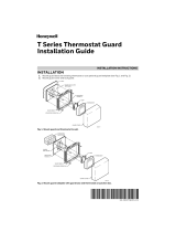
2.2 Wallplate installation
Loosen the locking screw at the bottom of the thermostat. Note
the screw is captive and cannot be removed from the wallplate.
Separate the thermostat from the wallplate as per Figure 1.
Position the wallplate against the wall and mark hole positions
with a pencil.
NOTE: Levelling is for esthetics only and will not affect the
performance of the thermostat.
Drill holes at the marked positions and insert supplied wall
anchors.
Pass the wires through the large opening at the bottom center of
the wallplate as per Figure 2.
Secure the wallplate to the wall with supplied mounting screws
as per Figure 3.
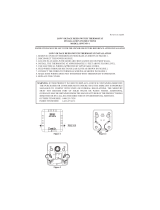
2.3 Wiring
It is important that you match the wire labels with the corresponding
terminals on the thermostat.
NOTE: Depending on your system, you might not need to connect to
all terminals.
Remove the jumper wire between Rh and Rc terminals if you have
both Rh and Rc wires as shown in the following illustration.
If a wire label does not match a terminal designation on the thermo-
stat, refer to the following illustration to find the corresponding alter-
nate wire label.
Do not connect wires identified as C, C1, X or B as these
wires are not used with this thermostat. Wrap the bare
end of these wires with electrical tape, so they cannot
touch and short out other wires.
Introduction
1.
Installation
2.
Rh, 4 or V
R
W1 or H
Y1 or M
F
RTH111/RTH221
Installation Guide
Programmable and Non-programmable Thermostats