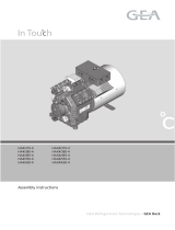
Danfoss BOCK HGX34e is a semi-hermetic four-cylinder reciprocating compressor with oil pump lubrication and suction gas cooled drive motor. It's suitable for use in refrigeration systems with refrigerants R134a and R407C. The compressor comes factory-filled with BOCK lub E55 oil and has a maximum permissible operating pressure of 19/28 bar (LP/HP). It can operate within an ambient temperature range of -20°C to +60°C and has a maximum permissible discharge end temperature of 140°C. The compressor has a nominal rotation speed of 27.3 Hz at 50 Hz and a displacement of 32.8 cm³/rev.
Danfoss BOCK HGX34e is a semi-hermetic four-cylinder reciprocating compressor with oil pump lubrication and suction gas cooled drive motor. It's suitable for use in refrigeration systems with refrigerants R134a and R407C. The compressor comes factory-filled with BOCK lub E55 oil and has a maximum permissible operating pressure of 19/28 bar (LP/HP). It can operate within an ambient temperature range of -20°C to +60°C and has a maximum permissible discharge end temperature of 140°C. The compressor has a nominal rotation speed of 27.3 Hz at 50 Hz and a displacement of 32.8 cm³/rev.


-
 1
1
-
 2
2
-
 3
3
-
 4
4
-
 5
5
-
 6
6
-
 7
7
-
 8
8
-
 9
9
-
 10
10
-
 11
11
-
 12
12
-
 13
13
-
 14
14
-
 15
15
-
 16
16
-
 17
17
-
 18
18
-
 19
19
-
 20
20
-
 21
21
-
 22
22
-
 23
23
-
 24
24
-
 25
25
-
 26
26
-
 27
27
-
 28
28


Danfoss BOCK HGX34e is a semi-hermetic four-cylinder reciprocating compressor with oil pump lubrication and suction gas cooled drive motor. It's suitable for use in refrigeration systems with refrigerants R134a and R407C. The compressor comes factory-filled with BOCK lub E55 oil and has a maximum permissible operating pressure of 19/28 bar (LP/HP). It can operate within an ambient temperature range of -20°C to +60°C and has a maximum permissible discharge end temperature of 140°C. The compressor has a nominal rotation speed of 27.3 Hz at 50 Hz and a displacement of 32.8 cm³/rev.
Ask a question and I''ll find the answer in the document
Finding information in a document is now easier with AI
Related papers
-
Danfoss BOCK HG22e GEA Semi Hermetic Compressor User guide
-
Danfoss BOCK FK40 User guide
-
Danfoss BOCK FK50 GEA Vehicle Compressor User guide
-
-
Danfoss BOCK HGX34e A Installation guide
-
-
Danfoss BOCK HG4 GEA Semi Hermertic Compressor User guide
-
Danfoss PT1000 Ally Programmable Wireless Control System User guide
-
Danfoss WND-WR-MB Opt 38K Installation guide
-
Danfoss ET9100 Operating instructions
Other documents
-
Universal Audio V230523A User guide
-
LG RCAW070PBAA Owner's manual
-
Monster AIRMARS KM6S Gaming Keyboard User manual
-
GEA Bock HGX2/70-4 CO2 T Assembly Instructions Manual
-
 GEA Bock In Touch HA4/465-4 Assembly Instructions Manual
-
Hanbell RC2-320BF User manual
-
-
-
 Frick TDS Rotary Screw Compressor Installation Operation and Maintenance Guide
-
 Hussmann IR6B4060 User manual


