Page is loading ...

AQ451736787778en-000201
BOCK
®
HGZ7
Operating guide
Bock GmbH, Benzstr. 7
72636 Frickenhausen, Germany
BOCK
HGZX7/1620-4 R404A/R507 HGZX7/1620-4 R410A
HGZX7/1860-4 R404A/R507 HGZX7/1860-4 R410A
HGZX7/2110-4 R404A/R507 HGZX7/2110-4 R410A
HGZX7/1620-4 R448A/R449A HGZ7/1620-4 R22
HGZX7/1860-4 R448A/R449A HGZ7/1860-4 R22
HGZX7/2110-4 R448A/R449A HGZ7/2110-4 R22
Translation of the original instructions

D
GB
F
E
2 | AQ451736787778en-000201 © Danfoss | Climate Solutions | 2023.07
About these instructions
Read these instructions before assembly and before using the compressor. This will avoid misunder-
standings and prevent damage. Improper assembly and use of the compressor can result in serious
or fatal injury.
Observe the safety instructions contained in these instructions.
These instructions must be passed onto the end customer along with the unit in which the compres-
sor is installed.

D
GB
F
E
© Danfoss | Climate Solutions | 2023.07 AQ451736787778en-000201| 3
Contents Page
1 Safety 4
1.1 Identication of safety instructions
1.2 Qualications required of personnel
1.3 General safety instructions
1.4 Intended use
2 Product description 6
2.1 Short description standard design
2.2 ain and functional parts
2.3 Short description optional design
2.4 Name plate
2.5 Type key
3 Areas of application 9
3.1 Refrigerants
3.2 Oil charge
3.3 Limits of application
3.4 Subcooling temperature
4 Description of functions 14
4.1 Two-stage refrigeration circuit with liquid subcooler
5 Compressor assembly 16
5.1 Storage and transportation
5.2 Setting up
5.3 Installation of the liquid subcooler system (optional design)
5.4 Installation example, liquid subcooler with accessories
5.5 Factory-installed liquid subcooler system (optional design)
5.6 Pipe connections
5.7 Pipes
5.8 Laying suction ans pressure lines
5.9 Operating the shut-off valves
5.10 Operating mode of the lockable service connections
6 Electrical connection 23
6.1 Information for contactor and motor contactor selection
6.2 Circuit diagram for part-winding start
6.3 Standard motor, design for direct or partial winding start
6.4 Electronic trigger unit MP10
6.5 Connecting the trigger unit MP10
6.6 Functional test of the trigger unit MP10
6.7 Oil sump heater (accessories)
7 Commissioning 30
7.1 Preparations for start-up
7.2 Pressure strengh test
7.3 Leak test
7.4 Evacuation
7.5 Refrigerant charge
7.6 Start-up
7.7 Avoid slugging
8 Maintenance 33
8.1 Preparation
8.2 Work to be carried out
8.3 Spare parts recommendation/accessories
8.4 Replacing the valve plates
8.5 Lubicants / oil
8.6 Decommissioning
9 Technical data 36
10 Dimensions and connections 37
11 Declaration of incorporation 40

D
GB
F
E
4 | AQ451736787778en-000201 © Danfoss | Climate Solutions | 2023.07
1.2 Qualicationsrequiredofpersonnel
DANGER Indicates a dangerous situation which, if not avoided,
will cause immediate fatal or serious injury.
WARNING Indicates a dangerous situation which, if not avoided,
may cause fatal or serious injury.
CAUTION Indicates a dangerous situation which, if not avoided,
may cause fairly severe or minor injury.
ATTENTION Indicates a situation which, if not avoided,
may cause property damage.
INFO Important information or tips on simplifying work.
WARNING Inadequatelyqualiedpersonnelposestheriskofaccidents,the
consequencebeingserious orfatalinjury.Workoncompressors
isthereforereservedforpersonnelwhichisqualiedtoworkon
pressurized refrigerant systems:
• For example, a refrigeration technician, refrigeration mechatronic
engineer. As well as professions with comparable training, which
enables personnel to assemble, install, maintain and repair
refrigeration and air-conditioning systems. Personnel must be capable
of assessing the work to be carried out and recognising any potential
dangers.
1.1 Identicationofsafetyinstructions:
1| Safety

D
GB
F
E
© Danfoss | Climate Solutions | 2023.07 AQ451736787778en-000201| 5
1.4 Intended use
1.3 General safety instructions
WARNING Risk of accidents.
Refrigerating compressors are pressurised machines and as such
call for heightened caution and care in handling.
The maximum permissible overpressure must not be exceeded,
even for testing purposes.
Risk of burns!
- Depending on the operating conditions, surface temperatures of
over 60°C on the discharge side or below 0°C on the suction side
can be reached.
- Avoid contact with refrigerant necessarily.
Contact with refrigerant can cause severe burns and skin
damage.
WARNING The compressor may not be used in potentially explosive
environments!
These assembly instructions describe the standard version of the compressor named in the title
manufactured by Bock. Bock refrigerating compressors are intended for installation in a machine
(within the EU according to the EU Directives 2006/42/EC Machinery Directive, 2014/68/EU Pressure
Equipment Directive).
Commissioning is permissible only if the compressor has been installed in accordance with these as-
sembly instructions and the entire system into which it is integrated has been inspected and approved
in accordance with legal regulations.
The compressors are intended for use in refrigeration systems in compliance with the limits of
application.
Only the refrigerant specied in these instructions may be used.
Any other use of the compressor is prohibited!
1| Safety

D
GB
F
E
6 | AQ451736787778en-000201 © Danfoss | Climate Solutions | 2023.07
2| Product description
Oil drain plug
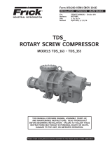
Semi-hermetic, two-stage, six cylinder reciprocating compressor with suction-gascooled
drive motor.
Stages divided into LP / HP at the ratio of 2 : 1
Compressor with intermediate pressure shut-off mounted and insulated.
2.1 Short description standard version
Dimension and connection values can be found in Chapter 10
Oil pump
Suction shut-off valve
Name plate
Notice
CE certication
for piping (only for
HGZ7/2110-4)
Oil sight glasses
Charge plug
Valve plate
Discharge
shut-off valve
Intermediate
pressure line
Fig. 1
Fig. 2
Terminal box
Intermediate
pressure
chamber
Bock GmbH, Benzstr. 7
72636 Frickenhausen, Germany
BOCK

D
GB
F
E
© Danfoss | Climate Solutions | 2023.07 AQ451736787778en-000201| 7
2| Product description
Liquid subcooler, expansion valve, solenoid valve, lter drier and a sight glass enclosed
separately, for individual, external mounting (Fig. 3).
Liquid subcooler, expansion valve, solenoid valve, lter drier and a sight glass mounted
directly to the compressor, piped and insulated (Fig. 4).
2.3 Short description optional version, mounted
Dimension and connection values can be found in Chapter 10
Sight glass
2.2 Short description optional version, enclosed
Fig. 3
Liquid
subcooler
Filter drierSolenoid valve
Fig. 4
Expansion
valve

D
GB
F
E
8 | AQ451736787778en-000201 © Danfoss | Climate Solutions | 2023.07
50 Hz
}
60 Hz
}
Observe the limits of application
diagrams!
1 Type designation
2 Machine number
3 Type code
4 Maximum operating current
5 Starting current (rotor blocked)
Y: Part winding 1
YY: Part windings 1 and 2
6 ND (LP):
max. admissible operating
pressur
e (g) Low pressure side
HD (HP):
max. admissible operating
pressur
e (g) High pressure side
7 Voltage, circuit, frequency
8 Nominal rotation speed
9 Displacement
VND = low pressure stage
VHD = high pressure stage
10 Voltage, circuit, frequency
11 Nominal rotation speed
12 Displacement
VND = low pressure stage
VHD = high pressure stage
13 Oil type lled at the factory
14 Terminal box protection type
Electrical accessories can change
the IP protection class!
2| Product description
/
HGZ 72110-4
X
Fig. 5
2.4 Name plate (example)
2.5 Type key (example)
1) HGZ = Hermetic gas cooled (suction gas cooled), two-stage
2) X = Ester oil filling (HFC refrigerant R404A/R507, R410A)
3) Possible alternative refrigerants R404A/R507, R410A, R448A/R449A, R22
R404A
Refrigerants 3)
Number of poles
Swept volume
Size
Oil charge ²)
Series ¹)
1
2
4
5
6
14
13
8
12
7
11
9
10
3
.
.
.
.
Y/YY
Y/YY
AN35455A040
Bock GmbH, Benzstr. 7
72636 Frickenhausen, Germany
BOCK
BOCK lub E55

D
GB
F
E
© Danfoss | Climate Solutions | 2023.07 AQ451736787778en-000201| 9
3| Areas of application
The compressors are lled at the factory with the following oil type:
- für R404A/R507, R410A, R448A/R449A BOCK lub E55
- für R22 BOCK lub A46
Compressors with ester oil charge (BOCK lub E55) are marked with an X in the type
designation (e.g. HGZX7/2110-4 R404A).
3.1 Refrigerants
• HFKW : R404A/R507, R410A, R448A/R449A
• (H)FCKW: R22
3.2 Oil charge
INFO For refilling, we recommend the above oil types.
Alternatives: see chapter 8.5.
ATTENTION Compressor operation is possible within the operating limits.
These can be found in Bock compressor selection tool (VAP)
under vap.bock.de. Observe the information given there.
- Permissible ambient temperature (-20°C) - (+60°C)
- Max. permissible discharge end temperature 140 °C
-Max.permissibleswitchingfrequency12x/h.
- A minimum running time of 3 min. steady-state condition
(continuous operation) must be achieved.
For operation with supplementary cooling:
- Use only oils with high thermal stability.
- Avoid continuous operation near the threshold.
When operating in the vacuum range, there is a danger of air
entering on the suction side. This can cause chemical reactions,
a pressure rise in the condenser and an elevated compressed-gas
temperature. Prevent the ingress of air at all costs!
3.3 Limits of application
ATTENTION The oil level must be in the
visible part of the sight glass;
damage to the compressor is
possible if overfilled or under-
filled!
max.
min.
2,3 Ltr.
oil level
Fig. 6
~
~
ATTENTION Anyoperationwithfrequencyconverterisinadmissible.

D
GB
F
E
10 | AQ451736787778en-000201 © Danfoss | Climate Solutions | 2023.07
Max. permissible operating pressure (LP/MP/HP)1): 19/19/28 bar
Design for other areas
onrequest
3| Areas of application
1) LP = low pressure MP = intermediate pressure HP = high pressure
tO Evaporation temperature (°C)
tC Condensing temperature (°C)
∆tOh suction gas superheat (K)
Unlimited application range
Fig. 7
Fig. 8
R404A/R507
Anwendungsbereich
Baureihe HGZ
R404AR404A HGZX7/2110-4 - R404A R410AR410A HGZX7/2110-4 - R410A
R22R22 HGZ7/2110-4 - R22
tc
t0
Dtoh
Verdampfungstemperatur (°C)
Verflüssigungstemperatur (°C)
Sauggasüberhitzung (K)
Bezogen auf 1 Sauggas berhitzung0 Kü
Einsatzgrenzen
-20
-30
-40
-50
-60
20
30
40
50
60
58
Dtoh<10K
t (°C)
o
t (°C)
c
-45
-50
-55
-60
-65
20
30
50
60
-40 t (°C)
o
t (°C)
c
46
40
Dtoh<10K
-20
-30
-40
-50
-60
20
30
40
50
60
t (°C)
o
t (°C)
c
66
Dtoh<10K
10
30
50
60
-60 -50 -30
-40 -20 -10
t (°C)
o
t (°C)
c
-70
20
40
70
R448A/R449AR448A/R449A
∆
toh<10K
R448A/R449A

D
GB
F
E
© Danfoss | Climate Solutions | 2023.07 AQ451736787778en-000201| 11
Max. permissible operating pressure (LP/MP/HP)1): 19/19/28 bar
Design for other areas
onrequest
3| Areas of application
1) LP = low pressure MP = intermediate pressure HP = high pressure
tO Evaporation temperature (°C)
tC Condensing temperature (°C)
∆tOh suction gas superheat (K)
Unlimited application range
Fig. 9
Fig. 10
R410A
R22

D
GB
F
E
12 | AQ451736787778en-000201 © Danfoss | Climate Solutions | 2023.07
3| Areas of application
The design of the expansion valve on the compressor can be dened with the help of the diagram by
approximately calculating the subcooling temperature arising in the relevant operating
conditions (t0/tc).
Diagrams for determining the subcooling temperature at the output of the liquid subcooler.
3.4 Subcooling temperature
tU = Subcooling temperature at the
subcooler outlet (FUA)
tO = Evaporating temperature
Fig. 11
Fig. 12

D
GB
F
E
© Danfoss | Climate Solutions | 2023.07 AQ451736787778en-000201| 13
3| Areas of application
tU = Subcooling temperature at the
subcooler outlet (FUA)
tO = Evaporating temperature
Fig. 13
Fig. 14

D
GB
F
E
14 | AQ451736787778en-000201 © Danfoss | Climate Solutions | 2023.07
The refrigerant suctioned out of the evaporator (20) is compressed by the 4 cylinders of the LP stage
(2) to intermediate pressure MP. After that, the superheated refrigerant ows through the intermediate
pressure chamber (3), where it is cooled by the liquid subcooler system to reduce the discharge end
temperature. The refrigerant then ows through the intermediate pressure line (4) to the electric
motor of the compressor for to cool the motor. After this, the refrigerant is suctioned in by the two HP
cylinders (5) and compressed to the nal pressure.
Liquidsubcoolersystem
The liquid subcooler system consists of the components
- liquid subcooler (plate heat exchanger) (6)
- expansion valve (7)
- sight glass (8)
- solenoid valve (9)
- lter drier (10)
After the refrigerant reciever (15), the liquid line will be splitted into two lines:
Line A leads through the liquid subcooler (6) and the subcooled refrigerant ows to the
evaporator (20). Through Line B refrigerant is expanding through the expansion valve (7) into the
liquid subcooler (6) in order to subcool the refrigerant of line A and through the intermediate pressure
line (MP) to cool the superheated refrigerant, which is compressed from low pressure to intermediate
pressure chamber (3).
4| Description of functions

D
GB
F
E
© Danfoss | Climate Solutions | 2023.07 AQ451736787778en-000201| 15
4| Description of functions
Explanations
1 Compressor
2 Cylinder LP-stage
3 Intermediate pressure chamber MP
4 Intermediate pressure line MP
5 Cylinder HP-stage
6 Liquid subcooler
7 Reinjection valve
8 Sight glass
9 Solenoid valve
10 Filter drier
11 Damper, pressure line
12 Oil separator
13 Non-return valve
14 Condenser
15 Refrigerant receiver
16 Filter drier
17 Solenoid valve
18 Sight glass
19 Expansion valve (evaporator)
20 Evaporator
21 Liquid separator
22 Damper, suction line
23 Filter suction line
LP = Low pressure
MP = Intermediate pressure
HP = High pressure
FUE = Liquid subcooler, inlet
FUA = Liquid subcooler, outlet
4.1 Two-stagerefrigerationcyclewithliquidsubcooler
Scope of supply
Line A
Line B
Fig. 15

D
GB
F
E
16 | AQ451736787778en-000201 © Danfoss | Climate Solutions | 2023.07
5| Compressor assembly
Setup on an even surface or frame with sufcient load-
bearing capacity.
Compressor in principle rigidly install.
Provide adequate clearance for maintenance work.
Ensure adequate compressor ventilation.
Do not use in a corrosive, dusty, damp atmosphere or a
combustible environment.
Fig. 18
Fig. 19
Fig. 20
F
E
D
C
B
A
1
2
3
4
F
E
D
C
4
3
2
1
A
B
Tol.-Ang. DIN ISO 2768-mK
Ra Rz
Maß
Passung
Freigabe
Alternativbezug:
Baumustergeprüft
Teil inaktiv
Lieferantenzeichnung
-
-
K.-Auftrag:
PL:
Zeichnung ungültig
Entwicklungsstand
Teil keine Serie
120
400
±0.5
über 0.5
bis 6
Benzstraße 7 - 72636 Frickenhausen - Germany - www.bock.de
-
-
Unbemaßte Radien:
-
Diese Zeichnung ist unser Eigentum!
Sie darf ohne unsere Genehmigung weder nach-
gebildet, vervielfältigt, oder Dritten Personen zu-
gänglich gemacht werden. Der Nachbau nach
dieser Zeichnung, oder an Hand der nach dieser
Zeichnung hergestellten Gegenstände durch den
Abnehmer oder Dritte ist nicht gestattet.
Wir behalten uns alle Rechte, gemäß DIN ISO 16016
an dieser Zeichnung vor.
Bearb.
Datum
Änderungs-Nr.
Werkstoff:
Ausgangsteil, bzw. Rohteil:
-
-
Gepr.
Name
Datum
19.04.
Werkstückkanten
DIN ISO 13715
Ersatz für:
Ersetzt durch:
Erstellt
2010
Geprüft
-
Kurz
Zone
1/x
Oberflächenbehandlung / Härte:
-
Blatt:
Änderungsbeschreibung
400
Benennung:
±0.8
1000
30
6
-
±0.3
120
30
±0.2
Zeichn.-Nr. Teile-Nr.
Oberflächenangaben ISO 1302
x.xxxx-xxxxx.x
Zust.
Gußtoleranzen:
Gewicht: (kg)
±0.1
Maßstab:
1:1
Wasserwaage
für Indesign
Der Lieferant muß sicherstellen, dass die Ware in
einwandfreiem Zustand angeliefert wird (Korrosions-
schutz, Verpackung für sicheren Transport).
Rz 25
Rz 160
s
25
z
y
x
w
u
t
0,05
Rz 1,6
0,3
0,7
1,6
2
Rz 16
6,3
Rz 63
Rz 6,3
Rz 12,5
F:\user\kurz\3D Sachen\3D Teile\Zeichnungen\Wasserwaage
INFO Newcompressorsarefactory-lledwithinertgas.Leavethisser-
vice charge in the compressor for as long as possible and prevent
the ingress of air. Check the compressor for transport damage
before starting any work.
?
5.1 Storage and transportation
Use transport eyelet.
Do not lift manually!
Use lifting gear!
Storage at (-30°C) - (+70°C), maximum permissible relative humidity
10% -95 %, no condensation.
Do not store in a corrosive, dusty, vaporous atmosphere or in a com-
bustible environment.
Fig. 17
Fig. 16
5.2 Setting up
ATTENTION Fittings (e.g. pipe holders, additional units, mounting parts etc.) on
the compressor are not permissible!

D
GB
F
E
© Danfoss | Climate Solutions | 2023.07 AQ451736787778en-000201| 17
5.3 Installationoftheliquidsubcoolersystem (optional version)
Separately enclosed components:
Liquid subcooler
Reinjection valve
Solenoid valve
Filter drier
Sight glass
Screw-in sleeve, solder adapter and seals
Please check for completeness of parts before beginning installation.
Assembly:
Pipe connections:
For connections, see dimension diagram Chapter 10.
System design, piping and necessary support points for the individual components must be
carefully planned and carried out.
Properly insulate liquid subcooler against condensation and heating and the related loss of
performance.
For rigidity reasons, the use of stainless steel pipes with a wall of 1 mm is preferred. The pipes
must be free of tension during and after soldering to prevent possible breaks lateron.
1
2
3
4
5
6
5| Compressor assembly
Fig. 21
INFO Observe manufacturer‘s instructions!
INFO The points listed here represent general guidelines and information
on how to pipe and connect the subcooler unit. To perform this work
technical knowledge and skill as well as proof of a hard-soldering
testcerticateinaccordancewithDINEN13133isrequired.
INFO Useonlysuitablehardsolderandux.Solderunderaninertgas
atmosphere when copper components are to be soldered! The
accompanying expansion valve is designed and adjusted for the
compressor and the listed refrigerant (sensor charge, nozzle).
Only use expansion valves approved and supplied by Bock!
INFO The intermediate pressure line and intermediate pressure chamber
are fully insulated at the factory. To mount the expansion valve,
cut the insulation as shown in the marked area in Fig. 22, page 18.
Correct sensor placement is marked by an unpainted area on the
pipe.
ATTENTION To avoid vibration cracks in the subcooler system, the individual
components must be mounted directly to the compressor or
installed as a decoupled unit!
1
2
3
4
5
6

D
GB
F
E
18 | AQ451736787778en-000201 © Danfoss | Climate Solutions | 2023.07
5| Compressor assembly
RConnection of pressure compensation line for expansion valve 7/16" UNF
W Refrigerant injection connection M22 x 1,5
X Schrader connection for intermedie-pressure gauge 7/16" UNF
Y Position of temperature sensor / unpainted
Fig. 22
Intermediate
pressure line
(Shown without
insulation)
Y
R
X
W
Intermediate
pressure chamber

D
GB
F
E
© Danfoss | Climate Solutions | 2023.07 AQ451736787778en-000201| 19
5| Compressor assembly
1 Liquid subcooler 5 Expansion valve FUA Liquid subcooler,
2 Filter drier 6 Temp. sensor expansion valve Outlet
3 Solenoid valve 7 Pressure compensation connection FUE Liquid subcooler,
4 Sight glass Inlet
Dia.16 mm Dia.6 mm
Dia.12 mm
Dia.12 mm Dia.12 mm
FUE
Fig.23
5.4 Installationexample,liquidsubcoolerwithaccessories
GB
INFO General notes:
Sensor lines, wires, etc. should not be attached with cable
binders directly to pipes or frames; otherwise, the thin pipes
may be worn through. It is better to run them through spiral
protective tubes.
If the compressor will be set up outside, UV-resistant materials
should be used.
X
Y
Line A
to the evaporator
Dia. 16 mm
Heat
insulation
Line B
Dia. 16 mm
Dia. 16 mm
from the receiver
Line B
Intermediate pressure
chamber MP

D
GB
F
E
20 | AQ451736787778en-000201 © Danfoss | Climate Solutions | 2023.07
5.6 Pipe connections
The pipe connections have graduated inside diameters so that pipes with
standart millimetre and inch dimensions can be used.
The connection diameters of the shut-off valves are rated for maximum
compressor output. Theactualrequiredpipecrosssectionmustbe
matched to the output. The same applies for non-return valves.
Fig. 25: graduated
internal diameter
5| Compressor assembly
ATTENTION Damage possible.
Superheating can damage the valve.
Remove the pipe supports therefore from the valve for soldering.
Only solder using inert gas to inhibit oxidation products (scale)
INFO A soldering suppot for tube diameter 54 mm is mounted to the
suction shut-off valve of the compressor.
A soldering support for tube diameter 2 1/8'' accompanies the
compressor.
Liquid subcooler, expansion valve, solenoid valve and the sight glass are mounted directly at the
compressor, piped and insulated.
5.5 Factory-installedliquidsubcoolersystem (optional design)
FUE
FUA
FUE: Liquid subcooler inlet
FUA: Liquid subcooler outlet
Fig.24
/