Intellisystem IT-ES308-IU-4F Owner's manual
- Category
- Network switches
- Type
- Owner's manual

1
IT-ES308-IU-4F
8-ports Unmanaged Industrial Ethernet Switch
Hardware Installation Guide
Introduction:
IT-ES308-IU-4F are a smart plug-and-play industrial
Ethernet switch, which can provide economical solution for your
Ethernet. Its dustproof fully sealed structure(protective case of
IP30 level), over-current, over-voltage and EMC protected
redundant double power input as well as built-in intelligent
alarm design can help system main tenancy personnel monitor
the network operation, which can work reliably in harsh and
dangerous environment.
IT-ES308-IU-4F supports 4 TP ports and 4 fiber ports
(IT-ES308-IU-4F: 4-ports 10/100Base-Tx, 4-ports 100Base-FX).
TP (RJ45) support 10/100Base-T(X), Full/Half duplex mode,
and auto MDI/MDI-X connection; 100BaseFX supports
single-/multi-mode, SC/ST/FC connector for optional.
Packing List:
The IT-ES308-IU-4F switch is shipped with following items.
1. Ethernet switch IT-ES308-IU-4F (plus terminal block) x1
2. Hardware Installation Guide x1
3. Product Warranty Statement x1
4. DIN-Rail setting fittings

2
Features:
1. Advanced Ethernet switch technical
2. IEEE802.3/802.3u/802.3x/802.3d,store and forward
3. 10/100M, F/H duplex, MDI/MDI-X auto negotiation
4. Broadcast storm protection
5. Relay output warning for power failure and port break alarm
6. Redundant 24VDC power input (12V~48VDC)
7. Designed for industrial applications. IP30 protection,
Rugged high-strength metal case
Panel Layout:
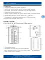
IT-ES308-IU-4F (4 TP ports and 4 fiber ports):
Top panel
Front panel.
1. Grounding screw
2. Terminal block (4 bits) for PWR1/PWR2
input, terminal block (2 bits) for relay output Bottom panel
3. DIP switch (ON is enable)

3
4. Program loading port
5. Heat dissipation orifices
6. DIN-Rail locating kit
7. Screw hole for wall mounting kit
8. 10/100Base-T(X) port
9.100Base-FX ports
10. Model name
11. Facility run indication LED
12. System alarm indication LED
13. Port indication LED
14. Power input PWR1 LED
15. Power input PWR2 LED Back panel
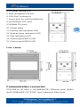
Units(mm)
Communication connector:
IT-ES308-IU-4F have 4 10/100BaseT(X) Ethernet ports (RJ45)
and 4 100BaseFX (SC/ST/FC type connector) fiber ports.

4
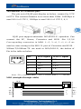
10/100BaseT(X) Ethernet port
The pin out of RJ45 port display as below, connect by UTP
or STP. The connect distance is no more than 100m. 100Mbps is
used 100Ωof UTP 5, 10Mbps is used 100Ωof UTP 3, 4, 5.
RJ45 port support automatic MDI/MDI-X operation. Can
connect the PC, Server, Converter and HUB .Pin 1,2,3,6
Corresponding connection in MDI. 1→3, 2→6, 3→1, 6→2 are
used as cross wiring in the MDI-X port of Converter and HUB. .
10Base-T/100Base-TX are used in MDI/MDI-X, the define of
Pin in the table as below.
NO.
MDI signal
MDI-X signal
1
TX+
RX+
2
TX-
RX-
3
RX+
TX+
6
RX-
TX-
4,5,7,8
—
—
Note: “TX±”transmit data±, “RX±”receive data±, “—”not use
MDI (straight-through cable)
1 8
1
8
RJ45
TX+
TX-
TX-
RX+
RX+
RX-
RX-
TX+
2
3
6
1
2
3
6
1

5
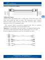
MDI-X (Cross-over cable)
100BaseFX port
100Base-FX full-duplex SM or MM port, SC/ST/FC type .The
fiber port must be used in pair, TX (transmit) port connect
remote switch’s RX (receive) port; RX (receive) port connect
remote switch’s TX (transmit) port.
The optical fiber connection supports the line to instruct
enhance the reliability of network effectively.
Suppose: If you make your own cable, we suggest labeling the
two sides of the same line with the same letter (A-to-A and
B-to-B, shown as below, or A1-to-A2 and B1-to-B2).
1
8
RJ45
TX+
TX-
TX-
RX+
RX+
RX-
RX-
TX+
2
3
6
1
6
1
2
3
(TX-)
(RX+)
(RX-)
(TX+)
(TX+)
(TX-)
(RX+)
(RX-)

6
LED Indicator:
LED indictor light on the front panel of IT-ES308-IU-4F .the
function of each LED is described in the table as below.
System indication LED
LED
State
Description
PWR1
ON
Power1 is being supplied to
OFF
Power1 is not being supplied
to
PWR2
ON
Power2 is being supplied to
OFF
Power2 is not being supplied
to
Alarm
ON
When the alarm is enabled,
power and the port’s link is
inactive.
OFF
Power and the port’s link is
active, not alarm
Run
ON
Common straight link mode
OFF
disable
Link/ACT 1~8
ON
TP port is active
Blinking
Data is being transmitted
OFF
TP port is inactive
Relay contact:
Relay access terminals located on the top panel, the terminal is a

7
set of device alarm relay normally open contact, no alarm in the
normal state when the open state, when there is no warning
message when it is closed. IT-ES308-IU-4F to support a relay
alarm output, external warning light or alarm buzzer, also can
add other digital acquisition device so that in the event of an
alarm to alert the operator when a timely manner.
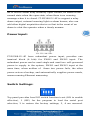
Power Input:
IT-ES308-IU-4F have redundant power input, provides one
terminal block (4 bits) for PWR1 and PWR2 input. The
redundant power can be used single and used two self-governed
power to supply to the system, PWR1 and PWR2 input at the
same time, when neither of these two power fails, the other
power acts as a backup, and automatically supplies power needs,
ensure running Ethernet reassuring.
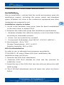
Switch Settings:
Top panel provides four DIP switch function is set (ON to enable
effective), 1 (ISP) for the program to load the serial port
selection, 2 to restore the factory settings; 3, 4 are reserved.

8
Changing the DIP switch status, must re-power.
Installation:
Before installation, confirm that the work environment meet the
installation require, including the power needs and abundant
space. Whether it is close to the connection equipment and other
equipment are prepared or not.
Installation require as below
1. Avoid in the sunshine, keep away from the heat fountainhead
or the area where in intense EMI.
2. Examine the cables and plugs that installation requirements.
3. Examine whether the cables be seemly or not (less than 100m)
according to reasonable scheme.
4. Screw, nut, tool provide by yourself.
5. Power need: Redundant, dual 24VDC (12VDC~48VDC)
6. Environment: -40 to 75°C
Storage Temperature: -45°C to 85°C
Relative humidity 10% to 95%
DIN-Rail Installation
In order to use in industrial environments expediently,
IT-ES308-IU-4F adopt 35mm DIN-Rail installation, the
installation steps as follows:
1. Examine the DIN-Rail attachment
2. Examine DIN Rail whether be firm and the position be
suitability or not.
3. Insert the top of the DIN-Rail into the slot just below the stiff
metal spring.
4. The DIN-Rail attachment unit will insert into place as shown
below.

9
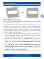
Wiring Requirements:
Be sure to disconnect the power cord before installing and/or
wiring your Ethernet Switch.
Calculate the maximum possible current in each power wire and
common wire. Observe all electrical codes dictating the
maximum current allowable for each wire size. If the current
goes above the maximum ratings, the wiring could overheat may
causing serious damage to your equipment. You should also pay
attention to the following items:
1. Use separate path to route wiring for power and devices. If
power wiring and device wiring paths must cross, make sure
the wires are perpendicular at the intersection point.
2. NOTE: Do not run signal or communications wiring and
power wiring in the same wire conduit. To avoid interference,
wires with different signal characteristics should be routed
separately.
3. You can use the type of signal transmitted through a wire to
determine which wires should be kept separate. The rule of
thumb is that wiring that shares similar electrical
characteristics can be bundled together.
4. Keep input and output wiring separated. It is strongly advised

10
that you label wiring to all devices in the system when
necessary.
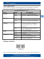
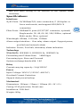
Specifications:
Interfaces
RJ45 Ports: 10/100BaseT(X) auto connection, F /H duplex or
force work mode, and support MDI/MDI-X
connection
Fiber Ports: 100BaseFX ports (SC/ST/FC connector, optional)
Single-mode: 20, 40, 60, 80, 100,120Km, optional
Multi-mode: 2Km, optional
Wavelength: 850nm, 1310 nm, 1550nm
Alarm output interface:One relay alarm output. Support power,
port link and network alarm
Indicator: Power, Port link, abnormity alarm indication
Technology
Standards: IEEE802.3, IEEE802.3x, IEEE802.3u
Forwarding and Filtrate Rate: 148810pps
Processing type: Store and Forward
System exchange bandwidth: 1.6G
Relay
Current carrying capacity: 1A@30VDC
Power
Input Voltage: 24VDC (12VDC~48VDC)
Overload Current Protection
Support dual power backup
Mechanical
Dimensions: 136mm×52mm×105mm (H×W×D)
Casing: IP30 protection, Metal case
Installation: DIN-Rail
Weight: 900g

11
Environmental
Operating Temperature: -40 to 75°C
Storage Temperature: -45 to 85 °C
Ambient Relative Humidity: 10% to 95% (non-condensing)
Approvals
EMI:FCC Part 15, CISPR (EN55022) class A
EN61000-4-2 (ESD), Level 4
EN61000-4-3 (RS),Level 3
EN61000-4-4 (EFT),Level 4
EN61000-4-5 (Surge),Level 4
EN61000-4-6 (CS),Level 4
EN61000-4-8,Level 5
Shock: IEC 60068-2-27
Free Fall: IEC 60068-2-32
Vibration: IEC 60068-2-6
Warranty: 5 years
Certifications:
-
 1
1
-
 2
2
-
 3
3
-
 4
4
-
 5
5
-
 6
6
-
 7
7
-
 8
8
-
 9
9
-
 10
10
-
 11
11


Intellisystem IT-ES308-IU-4F Owner's manual
- Category
- Network switches
- Type
- Owner's manual
Ask a question and I''ll find the answer in the document
Finding information in a document is now easier with AI
Related papers
-
Intellisystem IT-ES308-IU-1F Owner's manual
-
-
-
-
-
-
-
-
-
Other documents
-
 3onedata IES618-2F-4DI(RS-485)-P User manual
-
 Moxa Technologies EDS-G308 Hardware Installation Manual
-
Moxa EDS-2016-ML Series Quick setup guide
-
-
Moxa IMC-101-M-SC Installation guide
-
Moxa EDS-309 Series Quick setup guide
-
 Novartis IMC-101 User manual
-
-
-


