GREE MULTIU18HP211 Installation guide

Category
Split-system air conditioners
Type
Installation guide
Change for life
Installation & Owner's Manual
Original Instructions
Split Type Wall-mounted Air Conditioner
Model:
MULTIU18HP230V1DO
MULTIU24HP230V1DO
MULTIU36HP230V1DO
MULTIU42HP230V1DO
Thank you for choosing our product.
Please read this Owner’s Manual carefully before operation and
retain it for future reference.
If you have lost the Owner's Manual, please contact your local
distributor or visit www.greecomcomfort.com/resources for the
electronic version.
INTENTIONALLY BLANK
CONTENTS GENERAL INFORMATION
1
2
3
5
5
6
10
10
11
11
12
Technical Data
Electrical Connections
Installing The Outdoor Unit
Maintenance
Installation Dimension Diagram
Check After Installation
Bleeding
Conformity And Range
The Instructions Before Use
Name of Parts
Outdoor Unit Working Temperature Range
GENERAL
INSTALLER INFORMATION
In line with the company’s policy of continual product improvement, the aesthetic and dimensional
characteristics, technical data and accessories of this appliance may be changed without notice.
The products in this manual may be different from the ones you receive, due to different
models, some models have a display, some models do not. For the position and shape of the
display please refer to the your model.
This appliance is not intended for use by persons (including children) with reduced physical,
sensory or mental capabilities, or lack of experience and knowledge, unless they have been
given supervision or instruction concerning use of the appliance by a person responsible for
their safety.
Children should be supervised to ensure that they do not play with the appliance.
Exception Clauses
Manufacturer will bear no responsibilities when personal injury or
property loss is caused by the following reasons.
Explanation of Symbols
Please read this owner's manual carefully before operating the unit and retain it for consultation.
Instructions for installation and use of this product are provided by the manufacturer.
Only use the air conditioner as instructed in this booklet. These instructions are not intended to
cover every possible condition and situation. As with any electrical household appliance, common sense
and caution are therefore always recommended for installation, operation and maintenance.
Indicates a hazardous situation that, if not avoided, will
result in death or serious injury.
Indicates a hazardous situation that, if not avoided, could
result in death or serious injury.
Indicates a hazardous situation that, if not avoided, may
result in minor or moderate injury.
Indicates important but not hazard-related information,
used to indicate risk of property damage.
Indicates a hazard that would be assigned a signal word
WARNING or CAUTION.
WARNING
CAUTION
DANGER
N OTIC E
1. Damage the product due to improper use or misuse of the product;
2. Altering, changing, servicing or using the product with other equipment without
abiding by the instruction manual of manufacturer.
3. Upon verification, the defect of product is directly caused by corrosive gas;
4. Upon verification, the defects are due to transportation damage.
5. Operating, repairing or servicing the unit without following the instruction manual
or related regulations.
6. Upon verification, the problem or dispute is caused by the quality specification or
performance of parts and components that produced by other manufacturers;
7. Damage caused by natural disasters, corrosive environments or force majeure.
CONFORMITY AND RANGE
GENERAL INFORMATION This appliance can be used by children aged from 8 years and above and persons
with reduced physical,sensory or mental capabilities or lack of experience and knowledge if they have been given
supervision or instruction concerning use of the appliance in a safe way and understand the hazards involved.
Children shall not play with the appliance.
Cleaning and user maintenance shall not be made by children without supervision.
1
THE INSTRUCTIONS BEFORE USE GENERAL INFORMATION
WARNING
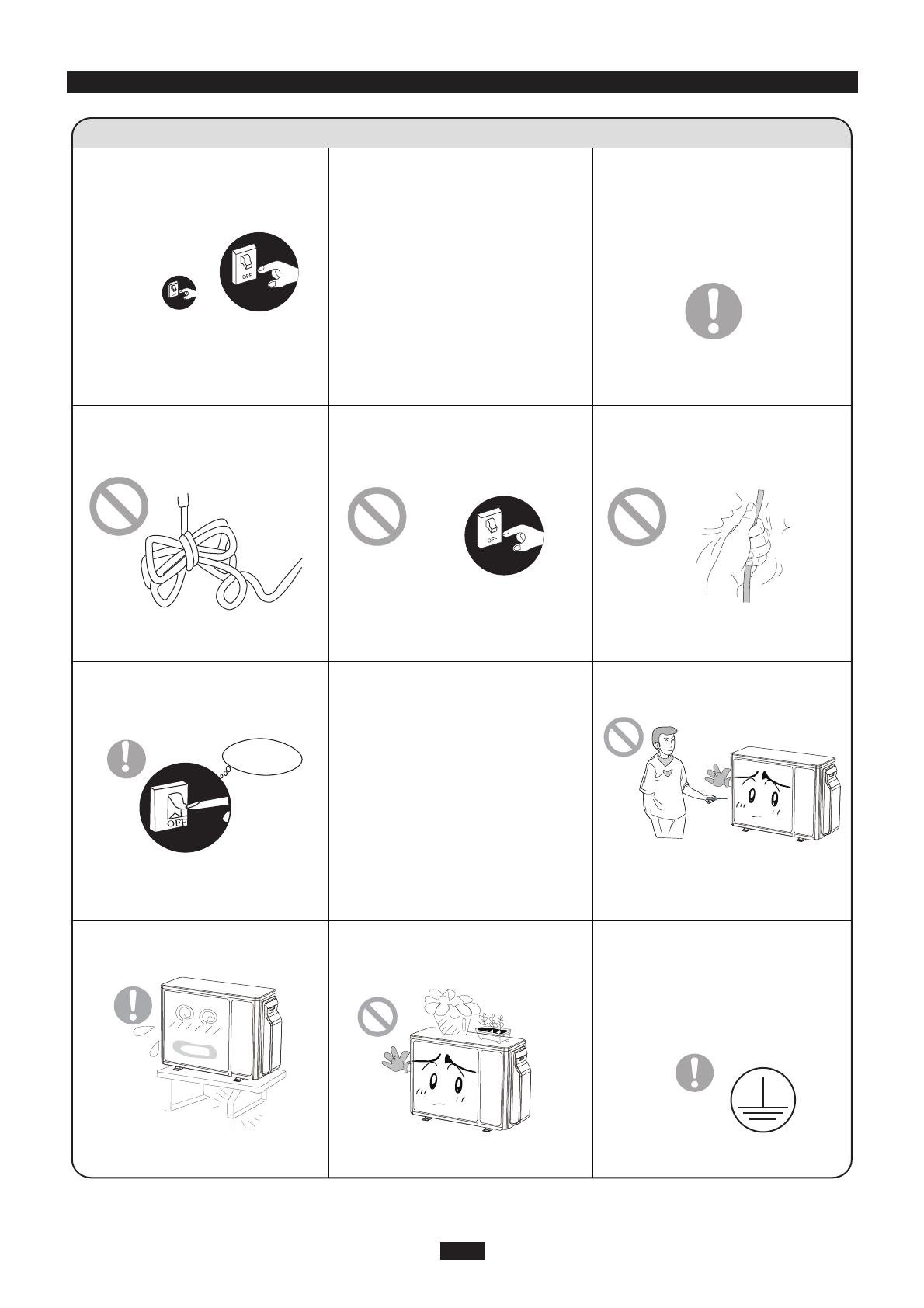
If you smell something burning or
see smoke, turn off the power supply
and contact an HVAC technician.
If the abnormity still exists,the unit
may be damaged,and may cause
electric shock or fire.
All power wiring must comply
with local, regional or national
electric codes.
Improper wiring can cause
electrical shock or fire.
If you won't be using your unit for
extended periods, disconnect the
power supply.
Residual dust build up could
cause overheating or fire.
Never damage electrical wiring or
use the electrical wire which is not
suited for this application.
It could cause overheating or fire.
When cleaning, turn the unit off
and disconnect power supply at
the breaker.
Cut off power supply
Not doing so may cause
electrical shock or damage.
The power supply must be
connected to a properly sized
circuit breaker. The unit will cycle
automatically according to your
settings. Do not frequently turn
your unit on or off, this may
interfere with its normal operation
Rated voltage of this air conditi-
oner 208/230V, 60Hz, The com-
pressor will vibrate sharply if the
voltage is too low, resulting in
damage to the refrigeration
system.
Electrical components are easy
damaged if the voltage is too
high.
Don't attempt to repair the air
conditioner yourself.
Improper repair could lead to an
electrical shock or fire, always
contacts an HVAC technician to
service or repair you unit.
Don't step on or place anything
on top of the outdoor unit.
Improper installation may cause
damage to the unit or injure
someone
Make sure the unit is safely
and securely installed.
Grounding: The unit must be
properly grounded. The ground
wire must be connected to the
appropriate grounding terminal
in the unit.
Serious injury or irreparable damage
could occur.
Never cut off or damage power
and control wiring. If the power
and signal control wires are
damaged, have them replaced
by an HVAC technician.
2
★ ★
★ ★
★ ★
★ ★
MULTIU18HP230V1DO
WARNING
If the supply wire is damaged, it must be replaced by the manufacturer or a licensed
HVAC technician or a similarly qualified person in order to avoid a hazard.
Be sure to disconnect the power supply before cleaning the air conditioner; to avoid an
electrical shock.
Wetting of air conditioner may cause the risk of electrical shock. Make sure not to wash
your air conditioner under any circumstance.
Volatile liquids such as thinner or gasoline will cause damage to the appearance of air
conditioner. (Only use soft dry cloth moist cloth clean the air conditioner cabinet).
Do not dispose this product as unsorted municipal waste. Dispose according to local
waste regulations.
The temperature of refrigerant circuit is high, please keep the interconnecting wire away
from the copper refrigerant lines.
Note: The above figures are only intended to be a simple
diagram of the appliance and may not correspond to
the appearance of the units that have been purchased.
No. Description
1 Air outlet grille
2Valve
OUTDOOR UNIT
1
2
MULTIU24HP230V1DO
WARNING
If the supply wire is damaged, it must be replaced by the manufacturer or a licensed HVAC technician or a
similarly qualified person in order to avoid a hazard.
Be sure to disconnect the power supply before cleaning the air conditioner; to avoid an electrical shock.
Wetting of air conditioner may cause the risk of electrical shock. Make sure not to wash your air conditioner
under any circumstance.
Volatile liquids such as thinner or gasoline will cause damage to the appearance of air conditioner. (Only use
soft dry cloth moist cloth clean the air conditioner cabinet).
Do not dispose this product as unsorted municipal waste. Dispose according to local waste regulations.
The temperature of refrigerant circuit is high, please keep the interconnecting wire away from the copper
refrigerant lines.
Note: The above figures are only intended to be a simple
diagram of the appliance and may not correspond to
the appearance of the units that have been purchased.
No. Description
1 Air outlet grille
2Valve
OUTDOOR UNIT
NAME OF PARTS GENERAL INFORMATION
3
1
2
MULTIU36HP230V1DO MULTIU42HP230V1DO
WARNING
If the supply wire is damaged, it must be replaced by the manufacturer or a licensed
HVAC technician or a similarly qualified person in order to avoid a hazard.
Be sure to disconnect the power supply before cleaning the air conditioner; to avoid an
electrical shock.
Wetting of air conditioner may cause the risk of electrical shock. Make sure not to wash
your air conditioner under any circumstance.
Volatile liquids such as thinner or gasoline will cause damage to the appearance of air
conditioner. (Only use soft dry cloth moist cloth clean the air conditioner cabinet).
Do not dispose this product as unsorted municipal waste. Dispose according to local
waste regulations.
The temperature of refrigerant circuit is high, please keep the interconnecting wire away
from the copper refrigerant lines.
Note: The above figures are only intended to be a simple
diagram of the appliance and may not correspond to
the appearance of the units that have been purchased.
No. Description
1 Air outlet grille
2Valve
OUTDOOR UNIT
1
2
NAME OF PARTS GENERAL INFORMATION
4
P
L
H
Minimum power wire section
mm
mm
mm
L
P
H
Fuse or circuit breaker
36 1/4
15
31 1/8
MODE
208/230V,60Hz
mm
A
A
2
MULTIU18HP230V1DO
35
5.3
Electrical data
Electricity supply
Size and clearance
P
L
H
Minimum power wire section
mm
mm
mm
L
P
H
Fuse or circuit breaker
36 1/4
15
31 1/8
MODE
208/230V,60Hz
mm
2
MULTIU24HP230V1DO
40
5.3
Electrical data
Electricity supply
Size and clearance
A
P
L
H
Minimum power wire section
mm
mm
mm
L
P
H
Fuse or circuit breaker
40
17 1/3
43 7/16
MODE
208/230V,60Hz
mm
2
MULTIU36HP230V1DO MULTIU42HP230V1DO
60
8.4
Electrical data
Electricity supply
Size and clearance
TECHNICAL DATA GENERAL INFORMATION
OUTDOOR UNIT WORKING TEMPERATURE RANGE GENERAL INFORMATION
5
Maximum cooling
Maximum heating
115°F(46°C)
75.2°F(24°C)
OutdoorsideDB/WB(°F °C )
Note: The above figures are only intended to be a simple
diagram of the appliance and may not correspond to the
appearance of the units that have been purchased.
An all-pole disconnect switch having a contact
separation of at least 3mm in all poles should be
connected to supply power wiring.
Wrong wire connections may cause malfunction of
some electric components. After fixing wire,
ensure that leads between connection to fixed
point have some space.
The connection pipes and the connection wiring of
unit A, unit B, unit C and unit D must correspond
to each other respectively.
The appliance shall be installed in accordance
with national wiring regulations.
MULTIU18HP230V1DO
Provide a circuit breaker with suitable capacity,
please note the following table. Circuit
breakers will prevent short-circuits and
overload. (Caution: do not use a fuse only for
circuit protection.
35A
Breaker capacity
Air-conditioner
MULTIU18HP230V1DO
ELECTRICAL CONNECTIONS INSTALLER
6
To the power supply
To unit B
Power wire
To unit A
connecting
wire
L1
L2
connecting
wire
INDOOR UNIT A INDOOR UNIT B
white
(blue)
white
(blue)
black
(brown)
red
(brown)
L2
L1
POWER
L1 L2
(yellow-
green)
green
(yellow-
green)
green
black white
(blue)
red
(brown)
(yellow-
green)
green
black
BA
1. Remove the handle at the right side plate of the
outdoor unit (one screw).
2. Remove the wire clamp, connect the power
connection wire to the appropriate terminal and
secure the connection. The wiring connections
must be consistent with the indoor unit terminal
connections. Wiring should match that of indoor
unit.
3. Secure power connection wire with a wire clamp.
4. Ensure all wire is securely attached.
5. Install the handle.
An all-pole disconnect switch having a contact
separation of at least 3mm in all poles should be
connected to supply power wiring.
Wrong wire connections may cause malfunction of
some electric components. After fixing wire, ensure
that leads between connection to fixed point have
some space.
The connection pipes and the connection wiring of
unit A, unit B, unit C and unit D must correspond to
each other respectively.
The appliance shall be installed in accordance with
national wiring regulations.
1. Remove the handle at the right side plate of the
outdoor unit (one screw).
2. Remove the wire clamp, connect the power
connection wire to the appropriate terminal and
secure the connection. The wiring connections
must be consistent with the indoor unit terminal
connections. Wiring should match that of indoor
unit.
3. Secure power connection wire with a wire clamp.
4. Ensure all wire is securely attached.
5. Install the handle.
Note: The above figures are only intended to be a simple
diagram of the appliance and may not correspond to the
appearance of the units that have been purchased.
Provide a circuit breaker with suitable capacity,
please note the following table. Circuit
breakers will prevent short-circuits and
overload. (Caution: do not use a fuse only for
circuit protection.
40A
Breaker capacity
Air-conditioner
MULTIU24HP230V1DO
MULTIU24HP230V1DO
ELECTRICAL CONNECTIONS INSTALLER
7
Power wire
L1 L2
To the power supply
To unit A
connecting
wire
To unit B
connecting
wire
To unit C
connecting
wire
INDOOR UNIT A INDOOR UNIT B
white
(blue)
white
(blue)
black
(brown)
red
(brown)
L2
L1
POWER
L1 L2
(yellow-
green)
green
(yellow-
green)
green
black white
(blue)
red
(brown)
(yellow-
green)
green
black
INDOOR UNIT C
white
(blue)
red
(brown)
(yellow-
green)
green
black
CBA
To the power supply
To unit A
connecting
wire
To unit B
connecting
wire
To unit C
connecting
wire
To unit D
connecting
wire
INDOOR UNIT A INDOOR UNIT B
white
(blue)
white
(blue)
black
(brown)
red
(brown)
L2
L1
POWER
L1 L2
(yellow-
green)
green
(yellow-
green)
green
black white
(blue)
red
(brown)
(yellow-
green)
green
black
INDOOR UNIT C
white
(blue)
red
(brown)
(yellow-
green)
green
black
C
INDOOR UNIT D
white
(blue)
red
(brown)
(yellow-
green)
green
black
DBA
Note: The above figures are only intended to be a simple
diagram of the appliance and may not correspond to the
appearance of the units that have been purchased.
An all-pole disconnect switch having a contact
separation of at least 3mm in all poles should be
connected to supply power wiring.
Wrong wire connections may cause malfunction of
some electric components. After fixing wire,
ensure that leads between connection to fixed
point have some space.
The connection pipes and the connection wiring
oft unit A, unit B, unit C and unit D must be
correspond to each other respectively.
The appliance shall be installed in accordance
with national wiring regulations.
MULTIU36HP230V1DO
Provide a circuit breaker with suitable capacity,
please note the following table. Circuit
breakers will prevent short-circuits and
overload. (Caution: do not use a fuse only for
circuit protection.
60A
Breaker capacity
Air-conditioner
MULTIU36HP230V1DO
ELECTRICAL CONNECTIONS INSTALLER
8
Power wire
L1 L2
1. Remove the handle at the right side plate of the
outdoor unit (one screw).
2. Remove the wire clamp, connect the power
connection wire to the appropriate terminal and
secure the connection. The wiring connections
must be consistent with the indoor unit terminal
connections. Wiring should match that of indoor
unit.
3. Secure power connection wire with a wire clamp.
4. Ensure all wire is securely attached.
5. Install the handle.
Note: The above figures are only intended to be a simple
diagram of the appliance and may not correspond to the
appearance of the units that have been purchased.
An all-pole disconnect switch having a contact
separation of at least 3mm in all poles should be
connected to supply power wiring.
Wrong wire connections may cause malfunction of
some electric components. After fixing wire, ensure
that leads between connection to fixed point have
some space.
The connection pipes and the connection wiring of
unit A, unit B, unit C and unit D must correspond to
each other respectively.
The appliance shall be installed in accordance with
national wiring regulations.
Provide a circuit breaker with suitable capacity,
please note the following table. Circuit
breakers will prevent short-circuits and
overload. (Caution: do not use a fuse only for
circuit protection.
To the power supply
To unit A
connecting
wire
To unit B
connecting
wire
To unit C
connecting
wire
To unit D
connecting
wire
To unit E
connecting
wire
INDOOR UNIT A INDOOR UNIT B
white
(blue)
white
(blue)
black
(brown)
red
(brown)
L2
L1
POWER
L1 L2
(yellow-
green)
green
(yellow-
green)
green
black white
(blue)
red
(brown)
(yellow-
green)
green
black
INDOOR UNIT C
white
(blue)
red
(brown)
(yellow-
green)
green
black
C
INDOOR UNIT D
white
(blue)
red
(brown)
(yellow-
green)
green
black
D
INDOOR UNIT E
white
(blue)
red
(brown)
(yellow-
green)
green
black
EBA
MULTIU42HP230V1DO
60A
Breaker capacity
Air-conditioner
MULTIU42HP230V1DO
ELECTRICAL CONNECTIONS INSTALLER
9
Power wire
L1 L2
1. Remove the handle at the right side plate of the
outdoor unit (one screw).
2. Remove the wire clamp, connect the power
connection wire to the appropriate terminal and
secure the connection. The wiring connections
must be consistent with the indoor unit terminal
connections. Wiring should match that of indoor
unit.
3. Secure power connection wire with a wire clamp.
4. Ensure all wire is securely attached.
5. Install the handle.
36Kx3
Max. connection pipe length 164 164 230 164 246
Max. connection pipe length
(Simple one indoor unit)
Models(ft)
Max. connection pipe length 246 164 246 262 262
82 82 82 82 82
INSTALLER
Vacuum pump Vacuum pump
Twisting moment (ft-lbs)
1/4'' 11-15
3/8'' 26-30 Vacuum pump
5/8'' 44-48
1/2'' 33-37 (8) Secure
3/4''
18 24 36 42K
52-55
unit need to be installed the indoor unit
2-way valve
(7)Turn to open fully
(2)Turn
Valve cap
conversion joint
10
INSTALLING THE OUTDOOR UNIT
Location
Use bolts to secure the unit to a flat, solid floor.
When mounting the unit on a wall or the roof, make
sure the support is firmly secured so that it cannot
move in the event of intense vibrations or a strong
wind.
Do not install the outdoor unit in pits or air vents
INSTALLER
Caution: Installation Must be Performed in
Accordance with the NEC/CEC by Authorized
Personnel Only.
Install the drain fitting and the drain hose
(for model with heat pump only)
Condensation is produced and flows from the out-
door unit when the appliance is operating in the
heating mode. In order not to disturb neighbours
and to respect the environment,install a drain fitting
and a drain hose to channel the condensate water.
Install the drain fitting and rubber washer on the
outdoor unit chassis and connect a drain hose to it
as shown in the figure.
82
36Kx4
82
42Kx2
82
42Kx3
82
42Kx4
82
42Kx5
Max. connection pipe length
(Simple one indoor unit)
1.The refrigerant pipes must not exceed the maximum
heights 33ft(18Kx2 & 24Kx2 & 24Kx3)
2.The refrigerant pipes must not exceed the maximum
heights 49ft(36x2&36x3&36x4&42x2&42x3&42x4&42x5).
Wrap all the refrigerant pipes and joints.
Tighten the connections using two wrenches wor-king
in opposite directions.
BLEEDING
Humid air left inside the refrigerant circuit can cause com-
pressor malfunction. After having connected the indoor
and outdoor units, bleed the air and humidity from the
refrigerant circuit using a vacuum pump.
Diameter
INDOOR
UNIT
Refrigerant fluid direction of fiow
3-way valve
Service
inlet
(2)Turn
(8) Secure Connect to the
indoor unit
(6) Open by 1/4 turn
Installing the pipes
(1) Unscrew and remove the caps from the 2-way and 3-
way valves.
(2) Unscrew and remove the cap from the service valve.
(3) Connect the vacuum pump hose to the service valve.
(4) Operate the vacuum pump for 10-15 minutes until an
absolute vacuum of 10 mm Hg has been reached.
(5) With the vacuum pump still in operation, close the
(7)Turn to open fully
Use suitable connecting pipes and equipment for
the refrigerant R410A.
Models(ft)18Kx2 24Kx2 24Kx3 36Kx2
(7) Turn the body of the 2-way and 3-way valves. Discon-
nect the vacuum pump hose.
(8) Replace and tighten all the caps on the valves.
Valve cap
low-pressure knob on the vacuum pump coupling.
(2)Turn
(8) Secure
Stop the vacuum pump.
(6) Open the 2-way valve by 1/4 turn and then close it
after 10 seconds. Check all the joints for leaks using
liquid soap or an electronic leak device.
Use suitable instruments for the refrigerant R410A.
Do not use mineral oils to clean the unit.
The installation must be done by trained and licensed service personnel adhereing to the instructions
provideded in this manual.
Contact a licensed HVAC contractor for installation to avoid any issues that will void the warranty.
Any disconnecting and relocation of a unit must be done by a qualified licensed HVAC technician.
Ensure that the minimum spacing requirements (below) are adhered to.
Do not use any other refrigerant than R410A.
MAINTENANCE INSTALLER
INSTALLATION DIMENSION DIAGRAM INSTALLER
11
MULTIU24HP230V1DO
MULTIU18HP230V1DO
MULTIU36HP230V1DO MULTIU42HP230V1DO
(Air inlet side)
(Air outlet side)
(Air inlet side)
79 in min
12 in min
(Air inlet side)
20 in min
12 in min
20 in min
12 in min
12 in min
20 in min
20 in min
79 in min
79 in min
(Air outlet side)
(Air outlet side)
12 in min
12 in min
20 in min
20 in min
12
CHECK AFTER INSTALLATION INSTALLER
Check Items
Is the installation secure?
Has the gas leakage been checked?
Is the thermal insulation of the unit
sufficient?
Is the drainage sufficient?
Does the power supply voltage match
the rated voltage specified on the
nameplate?
Are the refrigerant lines and wiring
correctly installed?
Do the line sizes comply with
requirements?
Are there any obstacles near the air
inlet and outlet of the indoor and out-
door units?
Is the refrigerant charge correct for
the length of refrigerant lines installed
Has the unit been safely grounded?
Problems Due to Improper Installation
The unit may drop, vibrate or make noises
May cause unsatisfactory cooling (heating)
problems
May cause condensation and water formation
The unit may break down or the components
may burn out
The unit may break down or the components
may burn out
The unit may break down or the components
may burn out
The unit may break down or the components
may burn out or not perform to specifications
Check to see if more refrigerant needs to
be added.
Risk of electrical shock
GREE ELECTRIC APPLIANCES, INC. OF ZHUHAI
Add: West Jinji Rd, Qianshan, Zhuhai,Guangdong, China, 519070
Tel: (+86-756) 8522218
Fax: (+86-756) 8669426
E-mail: [email protected] www.gree.com
U.S. CONTACT INFORMATION
TRADEWINDS, LLC
www.greecomfort.com/resources
Contractor Support 888-850-7928 | Mon–Fri 8AM-5PM EDT
66129932222
CAT NO: GREE_MULTIU_INSTALL & OWNERS_06162022
  • Page 1 1
  • Page 2 2
  • Page 3 3
  • Page 4 4
  • Page 5 5
  • Page 6 6
  • Page 7 7
  • Page 8 8
  • Page 9 9
  • Page 10 10
  • Page 11 11
  • Page 12 12
  • Page 13 13
  • Page 14 14
  • Page 15 15
  • Page 16 16

GREE MULTIU18HP211 Installation guide

Category
Split-system air conditioners
Type
Installation guide

Ask a question and I''ll find the answer in the document

Finding information in a document is now easier with AI