Page is loading ...

installation manual
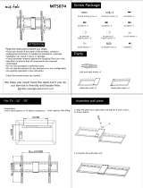
Split Type Room Air Conditioner

1
Table of Contents
Congratulations ......................................... 1
Safety Precautions .................................... 2
Notice for Installation ................................ 2
Before Installation
Tools needs for installation ...................... 3
Product Description ................................. 4
Installation site instruction ....................... 5
Pipe length elevation and additional
quantity of gas ......................................... 6
Oudoor unit installation ........................... 7
Installation
Installation of mounting plate .................. 8
Drill piping hole ........................................ 9
Installation of indoor unit ......................... 10
Installation of drain hole .......................... 9
Installation of connection pipe ................. 13
Piping connection-indoor unit .................. 14
Piping connection-outdoor unit ................ 15
Piping formation ...................................... 15
Electrical installation ................................ 16
Check the drainage ................................. 19
Air purging and leakage test ................... 20
Test and Running ....................................... 21
• Do not operate unit with horizontal louver is in
closed position.
• The indoor unit should be installed on the wall
at the height of 2.3 meters or more from the the
oor.
• The indoor unit should be installed allowing a
minimum clearance of 15cm from the ceiling.
• Before obtaining access to terminals, allsupply
circuit must be disconnected.
Congratulations
Congratulations and thank you for choosing a split-
typeairconditioner.Wearesureyouwillndyour
new air conditioner a pleasure to use.
Before you use the air conditioner, we recommend
that you read through the entire user manual, which
provides the description of the air conditioner and
its functions.
To avoid the risks that are always present when
you use an electrical appliance, it is important that
the air conditioner is installed correctly and that
you read the safety instructions carefully to avoid
misuse and hazards.
We recommend that you keep this instruction
booklet for future reference and pass it on to any
future owners.
After unpacking the air conditioner please check
it is not damaged. If in doubt, do not use the air
conditioner but contact your local authrised service
centre.
Information on disposal for users
• Most of the packing materials are recyclable.
Please dispose of those materials through
your local recycling depot or by placing them in
appropriate collection containers.
• If you wish to discard this air conditioner, please
contact your local authorities and ask for the
correct method of disposal.
Conditions of use
This appliance is intended to be used in household
and similar applications such as:
• Staffkitchenareasinshops,ofcesandother
working environments.
• Farm houses.
• By clients in hotels, motels, and other residential
type environments.
• Bed and breakfast type environments.
warning
environmental tip

2
Notice for Installation
1 Theunitmustonlybeinstalledbyaqualied
refrigeration mechanic and electrical work
carriedoutbyaqualiedelectricianaccording
to local or government regulations and in
compliance with this manual.
2 Beforeinstallation,pleasecontactaqualiedair
conditioner installer. Otherwise, the malfunction
may not be solved due to faulty installation.
3 If the power cord is damaged, replacement work
shall be performed by authorised personnel only.
4
5 The temperature of refrigerant circuit will be
high, please keep the interconnection cable
away from the copper tube.
6 This appliance is not intended for use by
persons (including children) with reduced
physical, sensory or mental capabilities, or lack
of experience and knowledge, unless they have
been given supervision or instruction concerning
use of the appliance by a person responsible for
their safety.
Young children should be supervised to ensure
that they do not play with the air conditioner.
7 If the unit is to be moved to another location or
disposedof,onlyasuitablyqualiedpersonis
permitted to undertake such work.
8 Takecarenottocatchngersonthefanblade
when adjusting vertical louvers.
9 This air conditioner uses R22 or R410A
refrigerant(Conrmbeforeinstallation).
Safety precautions
Please ready this installation manual and the
user manual before installation and carefully
store in a handy place for later reference.
Insidethismanualyouwillndmanyhelpfulhints
on how to use and maintain your air conditioner
properly.
Electrical work must be installed by a licensed
electrician. Be sure to use the correct rating of
the power plug and main circuit for the model to
be installed.
Incorrect installation due to ignoring this
instruction will cause harm or damage, and
theseriousnessisclassiedbythefollowing
indications.
Meanings of symbols used in this manual are
shown below:
This indicates information concerning your
personal safetyand how to avoid damaging the
appliance.
This symbol indicates information concerning
your personal safety.
This symbol indicates tips and information
about use of the appliance.
This symbol indicates tips and information
about economical and ecological use of the
appliance.
This symbol indicates never to do this.
Always do this.
caution
caution
warning
environmental tip
tips and information
An all-pole disconnection switch having a contact
separation of at least 3mm in all poles should be
connected in fixed wiring. For models with a power
plug, make sure the plug is within reach after
installation.

3
Before Installation
Tools Needs for Installation
Items Required for Installion
1 Level gauge
2 Screw driver
3 Electric drill
4 Hole core drill ( 55mm / 70mm)
5 Flaring tool set
6 Speciedtorquewrenches
7 Spanner (half union)
8 A glass of water
9 Hexagonal wrench (4mm)
10 Gas-leak detector
11 Vacuum pump
12 Gauge manifold
13 Users manual
14 Thermometer
15 Multimeter
16 Pipe cutter
17 Measuring tape
Note: Other necessary parts for the installation, besides the above mentioned, must be provided
by the customer/installer.
Number Name of Accessories Quantity
Indoor unit mounting plate 1
Clip anchor Not supplied
Self-tapping screw ST4 x 25
Remote control 1
Remote control holder 1
Screw for remote holder 2
Battery (AAA 1.5V) 2
Insulation material Not supplied
Connection piping assembly (refer to page 6) Varies by country
Insulation hose for refrgerant piping Not supplied
Wall clamp Not supplied
Drain hose Not supplied
Connection power cable Not supplied
Drain connector (Heat Pump model only, page 7) 1
Drain plug (Heat Pump model with capcity of over 4500W) 3
Thermal insulating pipe for extending drain hose 1
Flare nut (for suction pipe) 1
5 or 10

4
Light
Turbo
Healthy
Timer-On
Temp
Timer-Off
Swing
I feel
Eco
Fan
Clock
Mode
5
15
16
17
2 .3m above
15cm above
15cm above
Product Description
Space to the wall
Space to obstruction
30cm above
2m above
Air outlet side
Air inlet side
30cm above
50cm above
Space to the wall
Space to the ceiling
15cm above
Space to the wall
3m above
Air outlet side
Indoor
Unit
Space to the wall
Spacetotheoor
Outdoor
Unit
50cm above

5
Installation Site Instruction
More than 30cm
More than 30cm
More than 2m
More than 50cm
More than 15cm (ceiling)
More than
15cm
More than
15cm
Morethan2.3m(oor)
Lessthan2.5m(oor)
7 Select place about 1m or more away from a
TV set or any other electric appliance.
8 Selectaplacewheretheltercanbeeasily
taken out.
9 Do not use the unit in the laundry or by
swimming pool etc.
10 A minimum pipe run of 3 meters is required to
minimize vibration and noise.
11 Useastudndertolocatestudstoprevent
unnecessary damage to the wall.
12 Any variations in pipe length will/may require
adjustment to refrigerant charge.
13 Do not install near a door way.
Outoor Unit
1 Selectasitewherenoiseandoutowair
emitted by unit will not annoy neighbors.
2 Selectasitewherethereissufcient
ventilation.
3 Select a site where there is no obstruction
blocking the inlet and outlet.
4 The site should be able to withstand the full
weight and vibration of the unit.
5 Select a dry place, but do not expose the unit
to direct sunlight or strong wind.
6 Make sure that the outdoor unit is installed in
accordance with the installation instructions,
and is convenient for maintenance and repair.
7 Select a place where it is out of reach of
children and far from animals or plants.
8 Select a place where it is out of reach of
children and far from animals or plants.
9 Select a place where the unit keeps the
horizontal and aligned position.
10 Select at a place that respects the minimum
distances around the outdoor unit as below:
A proper installation site is vital for correct and
efcientoperationoftheunit.
Avoid the following sites where:
• strongheatsources,vapour,ammablegas
or volatile liquids are emitted.
• high-frequency electro-magnetic waves are
generated by radio equipment, welders or
medical equipment.
• salt-laden air prevails (such as close to
coastal areas).
• the air is contaminated with industrial vapours
and oils.
• the air contains sulphurous gas such as in hot
spring zones.
• corrosion or poor air quality exists.
Indoor Unit
1 The air inlet and outlet should be away from
the obstructions. Ensure the air can be blown
through the whole room.
2 Select a site where the condensing water can
be easily drained out, and where it is easily
connected for the outdoor unit.
3 Select a place where it is out of reach of
children.
4 Select the place where the wall is strong
enough to withstand the full weight and
vibration of the unit.
5 Be sure to leave enough space to allow
access for routine maintenance.
For optimum performance, the indoor unit
should be installed on the wall at a height
2.3metersormoreabovetheoorbutless
than2.5metersfromtheoor.
6 Make sure that the indoor unit is installed in
accordance with installation dimension as
below:

6
Pipe Length Elevation and Additional Quantity of Gas
• The outdoor unit is charged with the
refrigerant for standard pipe length.
• When the connecting pipe length is longer
than standard length, additional refrigerant
should be added into the unit according
the above table through the service port on
3-way service valve on the outdoor unit.
• Please maintain the shortest distance (3 to 5
meters) and shortest misalignment possible
between the indoor and outdoor units.
• The maximum allowance length and height
is based on reliability.
• Exceeding the maximum may cause poor
performance or malfunction.
• When the level difference between indoor
and outdoor units is greater than maximum
height, or when the outdoor unit is installed
above the indoor unit, oil trap should be
installed every 5-7 meters.
Outdoor unit
Outdoor unit
Maximum length
Maximum length
Indoor unit
Maximum height
Indoor unit
Oil trap
Rooftop Installation
1 If the outdoor unit is installed on a roof
structure, be sure to level the unit.
2 Ens ure the roof structure and anchoring
method are adequate for the unit location.
3 If the outdoor unit is installed on roof
structures or external walls, this may result in
excessive noise and vibration, and may also
be classed as non-serviceable installation.
Piping length under 5m
Piping length 5m or more
caution
Maximum height
Cool
Capacity (W)
Suction Pipe
Diameter
Discharge Pipe
Diameter
Standard
Length (m)
Maximum
Length (m)
Maximum
Height (m)
Additional
Refrigerant
(g/m)
COOLING ONLY
HEAT PUMP
2640 15 5 15
3520 15 5 15
5270 20 10 15
6450~8210 20 10 15
20
20
20
50
Ø6mm ~ 6.35mm (1/4”)
Ø6mm ~ 6.35mm (1/4”)
Ø6mm ~ 6.35mm (1/4”)
Ø6mm ~ 6.35mm (1/4”)
Ø9.52mm (3/8”)
5
5
5
5
Ø16mm ~ 15.88mm(5/8”)
Ø12mm ~ 12.7mm(1/2”)
Ø12mm ~ 12.7mm(1/2”)

7
Outdoor Unit Installation
Drain-water
hole
Drain
connecter
Chassis
Hose of inner dia. 16mm
(not provided)
Installation
Air inlet
Air inlet
Air outlet
• If a suspended installation is needed,
the installation bracket must allow the
xationaccordingtodimensionsonthe
gureabove.
• The wall where the unit will be installed
must be of solid brick, concrete or
provided with other reinforcement ways
toxthebracket.Thexationofthe
bracket to the wall and the bracket to
theairconditionermustberm,steady
and leveled.
• Anchortheoutdoorunitbyxingthe4holes
existent in its based with 4 bolts and nuts of
10 mm tightly (not included).
Place the outdoor unit over a horizontal
concrete or rigid surface (never directly over
grass or land).
Step 2: Outdoor Condensate Drainage
(only for heat pump model)
• During heating operation, the condensate and
defrosting water should be drained out reliably
through the drain hose.
• Install the outdoor drain connector in the drain-
water hole on the chassis of outdoor unit, and
attach the drain hose to the connector so that
the waste water formed in the outdoor unit can
be drained out.
• The drain-water hole must be plugged.
Whether to plug other holes will be determined
by the installer according to actual conditions.
• In case of a drain hose, the unit must be
installed on a base more than 3cm height.
Step 1: Securing of Outdoor Unit
Step 1: Installation of Mounting Plate
1 Fit the mounting plate horizontally on the wall
withveormoreself-tappingscrews(type
ST4x25, item 3 on page 3).
2 Be sure that the mounting plate has been
xedrmlyenoughtowithstandabout60kg.
Meanwhile, the weight should be evenly shared
by every screw.
3 3 If the wall is made of brick, concrete or the
like,drillve(5)ormoreholesof5mmdiameter
in the wall. Insert clip anchor (item 2 on page 3)
for appropriate mounting screws.
4 The water tray’s outlet for the indoor unit is two-
way drainage design. During installation, the
indoor unit should slightly slant to water tray’s
outlet for smooth drainage of condenser water.
Fit the mounting plate and drill holes in the wall
according to the wall structure and correcponding
mounting points on the mounting plate.
(dimensions are in mm unless otherwise stated)
caution
Cool Capacity (W/h) Mounting Plate type
2640 A
3520 B
5270 C
6450~7030
D
7030~8210
E
Power is supplied by indoor unit
Power is supplied by outdoor unit

8
to the
Mark on the middle of it Gradienter
Space
wall
150mm
above
Space
to the
wall
150mm
above
Wall
Wall
Left
55mm
Right
55mm
(Rear piping hole)
(Rear piping hole)
406
605
35
155
35
65
180
65
36
65
36
575
183
172
685
90
67
67
Ø70
Ø70
Φ65
206
80
60
380
143
Φ65
166
60
35
542
Φ
55
98
31
694
Φ
55
525.5
78
78
36
82 214
Mounting Plate Type A
Mounting Plate Type B
Mounting Plate Type C
Mounting Plate Type D

9
Outlet pipe of
indoor unit
Vinyl tape
Outlet pipe of
indoor unit
Drain hose
Outlet pipe of
indoor unit
Drain hose (narrow)
Vinyl tape
Insulating pipe
Indoor
Wall pipe
Seal putty
Outdoor
Ø55
or Ø70
5-10mm
Wall
Mounting Plate Type E
Step 2: Drill Piping Hole
1 Determine hole positions according to the
diagram.Drillone(1)hole(Ф55orФ70mm)
in the wall at a slight downward slant to the
outdoor side.
Piping hole Model
Ф55mm
Cooling capacity <6000W
Ф70mm
Cooling capacity >6000W
2 The inclination must be between 5 - 10mm in
order to ensure a good drain of condensed
water generated by the indoor unit.
Step 3: Installation of Drain Hose
Remove both supports
3 Insert the wall pipe into the hole to prevent
and wiring from being damaged when passing
through the whole.
4 Always use a wall hole conduit when drilling
metal grids, metal plates or the like.
5 For cooling capacity over 4500W models,
remove and dispose the two polystyrene lateral
rear supports from the indoor unit before the
installation.
1 Connect the drain hose to the outlet pipe of the
indoor unit. Bind the joint with vinyl tape.
2 Put the drain hose into insulating pipe.
186.5
260.5

10
Connected
Vinyl tape
Tailing 2
Tailing 1
bulge
Flooded
distortion
Do not put the
hose end into
water
Donotblockwaterow
with a rise.
Step 4: Installation of Indoor Unit
The piping can be output from right, rear right,
left or rear left.
3 Wrap the insulating pipe with wide vinyl tape
to prevent the shift of insulating pipe. Slant
the drain hose downward slightly for smooth
drainage of condensing water.
Insulating pipe
Outlet pipe of
indoor unit
• Cut off the tailings 1 when routing the
wiring only.
• Cut off the tailings 1 and tailings 2 when
routing both the wiring and piping.
Indoor Unit outline
Connection piping
1 When routing the piping and wiring from the left
or right side of indoor unit, cut off the tailings
fromthechassiswhennecessary(seegure
below).
2 The drain hose can be connected at two
different positions. Use the most convenient
postion and, if necessary, exchange the
position of drain cap and drain hose.
1 The insulating tube should be connected reliably
with the sleeve outside the outlet pipe.
2 The drain hose should be slanted downward
slightly,withoutdistortion,bulgeoructuation.
3 Do not put the outlet in the water.
• The drain hose is connected at the
rear left side of the indoor unit when
you receive the product.
Drain hose
(connected at
the rear left side)
Refrigerant
Piping
Drain hole
Drain cap
caution

11
Drain cap
• Follow the instruction as below for
exchanging the position of drain cap and
drain hose in case from left side to right.
(a) Pull out the drain cap at the rear right of
the indoor unit.
Drain cap
(b) Pull out the drain hose at the rear left of
the indoor unit.
Drain hose
(c) Put the drain cap into the drain hole at the
rear left of the indoor unit.
(d) Insert the drain hose into the drain hole at
the rear right of the indoor unit.
Drain hose
3 Pipe arrangement
• Arrange the pipe in the most convenient
direction and position.
Piping on the rear right side
Drain hose
from the left side
Piping on the right side
Piping on the right side
Piping on the rear right side
Drain hose
from the left side
Drain hose
from the right side
Drain hose
from the right side
Drain hose
from the left side
Drain hose
from the left side
Piping on the left side
Piping on the rear left side

12
• Turn lightly the cable to make the
connection easier later.
• Be careful not to let the drain hose
become slack.
• Heat insulate the connecting pipe.
• Be sure that the drain hose is located at
the lowest side of the buddle. Locating
at the upper side can cause drain pan to
overowinsideunit.
• Never cross connect or interwind the
power wire with any other wiring.
• Do not allow the piping to be exposed
out from the back of the indoor unit.
• If part of the drain hose is positioned
inside the room, wrap it with insulating
materials so as to prevent condensed
water from dropping.
• Connecttheindoorunitrst,thenthe
outdoor unit.
• Do not plug the cable to the indoor unit.
That must be done later.
Fixing lower hook
• Do not route both refrigerant piping and
drain hose from the right side to the left
side to prevent big gap between the
indoor unit and the wall.
Drain hose
from the right side
Piping and cable
from the right side
4 Take out the piping from body case, wrap
the piping, power cords, drain hose with the
tape and then make them pass through the
piping hose.
Do not put any object in the drain pan
located in the rear of the indoor unit, as the
condensed water is gathered there and
piped out of the room.
5 Hang the mounting slots of the indoor unit on
the upper hooks of the mounting plate and
checkifitisrmenough.
To ease the piping installation, put a spacer
between the indoor unit and the wall.
Removethespaceroncenished.
Indoor Unit
Piping
insulation
Upper hook
Mounting
plate
Spacer
Liquid pipe
Gas pipe
Connecting
cable
6 Press the lower left and right sides of the unit
against the mounting plate until the lower
hooks engage into their slots.
Ensuretheunitisrmlytted.
Drain hose
Drain hose
Mounting plate
7 The installation site should be 2.3 meters or more
abovetheoor.
caution
Upper hook
Connecting
cable

13
Refrigerant pipe connection
Step 5: Installation of Connection Pipe
Copper tube
Flare nut
1 Flaring work
Main cause for refrigerant leakage is due to
defectsinthearingwork.Carryoutcorrectaring
work using the following procedure:
A: Cut the pipes and the cable.
• Use the piping kit accessory (if applicable) or
pipes purchased locally.
• Measure the distance between the indoor and
the outdoor unit.
• Cut the pipes a little longer than the measured
distance.
• Cut the cable 1.5m longer than the pipe length.
Itisnotpossibletoputthemonafteraringwork.
D: Flaring work.
• Carryoutaringworkusingaringtoolas
shown below.
Handle
Bar
Bar
Yoke
Cone
Pipe
Copper pipe
Clamp handle
Red arrow mark
• Firmly hold copper pipe in a die according to
the dimension shown in the table below.
Oblique Roughness Burr
B: Burr removal
• Completely remove all burrs from the cut
cross section of pipe/tube.
• Face the end of the copper pipe/tube in a
downward direction as you remove burrs in
order to avoid burrs dropping into the tubing.
E: Check
• Comparetheareworkwiththeadjacent
diagram.
• If the pipe has any defect, cut off the enlarged
section and redo the work.
Pipe
Smooth all around
Face down
Reamer
Improperaring
Inclined CrackedDamaged
surface
Uneven
thickness
Even length all
around
C:Puttingarenuton
• Removearenutsattachedtoindoorand
outdoor unit, then put them on pipe/tube
having completed burr removal.
• Make an independent covering for each
pipe with the appropriate tubular isolation.
caution
Outer diam. (mm)
A (mm)
Max. Min.
Ф6 ~ 6.35(1/4”) 1.3 0.7
Ф9.52(3/8”) 1.6 1.0
Ф12 ~ 12.70(1/2”) 1.8 1.0
Ф16 ~ 15.88(5/8”) 2.4 2.2

14
Indoor Unit
pipe
Step 6: Piping Connection - Indoor Unit
B: Wrap the insulation material around the
connecting portion:
• Cover the indoor unit pipe and the connection
pipe with the heat insulation material. Bind
them together with vinyl tape so that there is
no gap.
A: Connecting the indoor unit tubing to the
connection piping:
• Alignthecentersofthepipesandsufciently
tightenthearenutwithyourhandsrst.
Cable ties
Pipings
Pipings
Flare nut
Flare nut
Indoor unit tubing
Torque
wrench
Indoor unit
tubing
Spanner(xed)
wrench
Torque
Spanner
Heat insulation
Insulation
material
Suction line
pipe
Liquid line
pipe
• Thentightenthearenutwithspannerand
torque wrench by referring the following:
Connection pipe
Vinyl tape
(wide)
Wrap with vinyl tape
Vinyl tape
(narrow)
Pipe
Connection
cable
Excessive torque can break the nut depending
on installation conditions.
• Ensure to Isolate separately the suction pipe
from the liquid pipe.
• Wrap the insulated pipes with vinyl tape in the
rear section for pipe housing. Fasten the power
cable to the pipes with vinyl tape.
• Wrap the piping, drain hose and power
cable tightly with vinyl tape so that they can
tintotherearpipinghousingsection.
Outer diam.
(mm)
Torque
(N.m)
Additional
Torque (N.m)
Ф6.35(1/4”) 15.7 (1.6kg.m) 19.6 (2.0kg.m)
Ф9.52(3/8”) 29.4 (3.0kg.m) 34.3 (3.5kg.m)
Ф12.70(1/2”) 49.0 (5.0kg.m) 53.9 (5.5kg.m)
Ф15.88(5/8”) 73.6 (7.5kg.m) 78.6 (8.0kg.m)
caution

15
Step 7: Piping Connection -
Outdoor Unit
Pipe
Drain hose
A:Alignthecentersofthepipesandsufciently
tightenthearenutwithyourhands.
Wrap with
vinyl tape
(wide)
Vinyl tape
(narrow)
Connection
power cable
C: Positioning the indoor unit:
• Remove the spacer.
• Hook the indoor unit onto the upper portion of
the mounting plate (Engage the hooks of the
mounting plate into the openings at the rear
top of the indoor unit).
Ensure that the hooks are properly seated on
the mounting plate by moving the indoor unit
in all directions.
B: Then,tightenthearenutwithtorquewrench
until the wrench clicks.
• Press the lower left and right sides of the unit
against the mounting plate until the hooks
engage into their slots (clicking sound).
Outdoor Unit
Liquid pipe
2-way
valve
Suction
pipe
3-way valve
Make sure to follow the torque table value
as below:
Upper hook
Connecting
cable
Drain hose
Mounting plate
Step 8: Piping Formation
A: Form the piping by wrapping the
connecting portion of the indoor unit with
insulation material and secure it with
narrow vinyl tape and wide vinyl tape.
• If you want to connect an additional drain
hose, the end of the drain hose outlet should
be routed above the ground. Secure the
drain hose appropriately.
Fixing lower hook
Outer diam.
(mm)
Torque
(N.m)
Additional
Torque (N.m)
Ф6.35(1/4”) 15.7 (1.6kg.m) 19.6 (2.0kg.m)
Ф9.52(3/8”) 29.4 (3.0kg.m) 34.3 (3.5kg.m)
Ф12.70(1/2”) 49.0 (5.0kg.m) 53.9 (5.5kg.m)
Ф15.88(5/8”) 73.6 (7.5kg.m) 78.6 (8.0kg.m)
Upper hook
Spacer
Mounting
plate

16
Safety Precautions
Step 9: Electrical Installation
B. In cases where the outdoor unit is
installed below the indoor unit level:
• Wrap the piping, drain hose and connecting
cable from the down to up.
• Secure the wrapped piping along the exterior
wall using saddle or equivalent.
Electrical safety rules before starting the
installation:
1 A dedicated power supply circuit and breaker
should be provided
for the products which
are not supplied with a
service cord and plug
in accordance with
local electrical safety
regulations.
2 The circuit breaker must have the functions of
magnetic tripping and heat tripping to prevent
short circuit and overload.
3 The appliance shall be installed in accordance
with national wiring regulations.
4 A circuit breaker with proper capacity must be
installed according to the table below.
Seal small openings
around piping with a
gum type sealer.
Wrapping
Pipe
Drain hose
Connection
cable
Drain hose
Trap is required to prevent water
from entering into electrical parts.
C. In cases where the outdoor unit is
installed above the indoor unit level:
• Wrap the piping and connecting cable from
the down to up.
• Form a trap to prevent water from entering
the room.
• Secure the wrapped piping along the exterior
wall using saddle or equivalent.
5 In case of problems in power supply, the air
conditioner must not be installed before the
customerxestheproblem.
6 Be sure the power supply matches the air
conditioner.
7 Ensure the live wire, neutral wire and
earth wire in the power socket are properly
connected.
8 Inadequate or incorrect electrical connections
maycauseelectricshock,reorsome
electrical parts to malfunction.
9 Before performing any electrical work, turn off
the main power to the system.
Earthing Requirements
1 Air conditioner is type I electric appliance. The
unit must be reliably earthed and connected
tothespecialearthdevicebythequalied
electrician.
Seal small openings
around piping with a
gum type sealer
Trap
Trap
Drain hose
Cooling
Capacity
(w)
Circuit
Breaker
2640 10A
3520 16A
5270 25A
6450~7030 25A
8210 32A

17
Installation of Indoor
Electric Wires
All wires between indoor and outdoor units
mustbeconnectedbyaqualiedelectric
contractor.
• If the length of the power cord is not
enough, please contact your supplier for
new power cord. Lengthen the power cord
by yourself is not allowed.
Wiring cover
2 The yellow-green wire in air conditioner is
the earthing wire which can not be used for
other purposes. Improper earthing may cause
electric shock.
3 The earth resistance should accord to the
national wiring regulation.
4 The user’s power must have reliable earthing
terminal. Do not connect the earthing wire with
the following:
• Water pipe
• Gas pipe
• Contamination pipe
1 Open the front panel and remove the wiring
cover by loosening the screw.
4 Wrap wires that are not connected with
insulating tape so that they do not touch any
electrical or metal parts.
5 Securethewiresrmlywiththecable
clamp.
6 Put the wiring cover back and screw it.
7 Reinstall the front panel.
2 Route the power connection cable and signal
control wire (for heap pump model only) from
back of the indoor unit and pull it toward the
front through the wiring hole for connection.
3 Connect and screw the wires onto the
terminalblockasidentiedbytheircolors.
caution
6450~8210W Cooling only type
yellow-
brown
green
26405270W Heat pump type
orange blue
black
violet
yellow-
green
outdoor unit connection
brown
violet
yellow-
green
orange
blue
black
outdoor unit connection
6450~8210W, Cooling Only models
2640~5270W, Heat Pump models
blue black
outdoor unit connection
yellow-
brown
green
blue black
outdoor unit connection
5270W
Heat pump type:
(Apply for Middle East area)
6450~7030W
Heat pump type:
(Power is supplied by indoor unit)
brown
violet
yellow-
green
orange
blue
black
outdoor unit connection
6450~8210W, Heat Pump models
(Power is supplied by outdoor unit)
7030~8210W
Heat pump type:
26405270W Cooling only type:
yellow-
green
blue black
outdoor unit connection
outdoor unit connection
2640~5270W, Cooling Only models
5270W Cooling only type:
(Apply for Middle East area)
Yellow-
green
Brown
Black
Blue

18
• After tightening the screws, pull the wire
slightlytoconrmwhetherit’srmornot.
• Do not connect two power cables
together to supply power to the air
conditioner.
• Do not extend the power cable conductor
by cutting.
Installation of Outdoor
Electric Wires
Terminal
block
1 1 Remove the handle on the right side plate of
outdoor unit by loosening the screw.
2 Take off wire cable clamp. Connect and
screw the power connection cable and signal
control wire (for heap pump model only) onto
the terminal block following corresponding
identicationnumbersandcolorsonthe
terminal blocks of indoor and outdoor units.
3 To prevent water from entering, make a trap
(“U”) in the connection wires (see page 16).
4 Wrap wires that are not connected with
insulating tape so that they do not touch any
electrical or metal parts.
5 Fix the power connection wires with wire
clamps.
6 Reinstall the handle.
caution
Handle
2640~5270W Cooling only type:
5270W Cooling only type:
(Apply for Middle East area)
yellow-
green
Black
(brown)
Blue
Indoor unit connection
6450~7030W Cooling only type:
(Power is supplied by indoor unit)
(Power is supplied by outdoor unit)
Yellow-
green
Brown
Indoor unit connection
2640~5270W Heat pump type:
2 4
5
N(1)
Blue
Blue
Black
Black
(Red)
Violet
Orange
Orange
Yellow-
green
Indoor unit connection
Yellow-
green
Brown
Violet
Indoor unit connection
Blue Black
(Red)
Orange
Yellow-
green
Brown
Violet
Indoor unit connection
6450~8210W, Cooling Only models
6450~8210W, Heat Pump models
2640~5270W, Heat Pump models
Black
Blue
Yellow-
green
Brown
Indoor unit connection
Black
Blue
5270W Heat pump type:
(Apply for Middle East area)
7030~8210W Cooling only type:
6450~7030W
Heat pump type:
(Power is supplied by indoor unit)
(Power is supplied by outdoor unit)
7030~8210W
Heat pump type:
Yellow-
green
yellow-
green
Brown
Indoor unit connection
Power
Black
Black
(brown)
Blue
Blue
L
N
Yellow-
green
Yellow-
green
Brown
Indoor unit connection
Power
Black
Black
(Brown)
Blue
Blue
L
N
2640~5270W, Cooling Only models

19
Afterconrmingtheaboveconditions,
prepare the wiring as follows:
• The screws which fasten the wiring to
the terminal block may come loose from
vibrations during transportation.
• Check and make sure all screws are well
xed.Otherwise,itcouldcauseburn-out
of the wires.
• Besurethecircuitcapacityissufcient.
• Ensure the starting voltage is maintained
at over 90% of the rated voltage marked
on the nameplate.
• Conrmthatthecablethicknessis
asspeciedinthepowersource
specication.
• Always install a Residual Current Device
(RCD) in wet or moist area.
• The following may be caused by voltage
drop: Vibration of a contactor, which will
damage the contact point, fuse blowing,
disturbance of the normal function of the
overload.
• The means for disconnection from a
power supply shall be incorporated in the
xedwiringandhaveanairgapcontact
separation of at least 3mm in each active
(phase) conductor.
Downward
slope
B. Check the drainage
• Carefully pour a glass of water on the
evaporator.
• Ensurethewaterowsthroughthedrain
hose of the indoor unit without any leakage
and goes out the drain exit.
Drain hose
C. Dain piping
• The drain hose should
point downward for
easydrainow.
Step 10: Checking the Drainage
A. Open and lift the indoor unit front panel.
• Hold the lower part of the left and right sides
of the panel, pull it against you and lift it stops
with a full support from the bracket.
• Do not place drain piping as indicated below:
Panel
bracket
caution
Accumulated
drain water
Do not rise
Tip of drain
hose dipped
in water
Air
Space less
than 50mm
Water
leakage
Water
leakage
Water
leakage
Ditch
/