Page is loading ...

8/16/32 PS/2 KVM over IP switch
1
8 port / 16 port / 32 port
PS/2 IP-KVM SWITCH
USER’S MANUAL
Rev 1.0

8/16/32 PS/2 KVM over IP switch
2
TABLE OF CONTENTS
1. THE QUICK INSTALLATION GUIDE
2. INTRODUCTION
2.1 When the server is up and running
2.2 When the sever is dead
2.3 Features
2.4 Package contents
2.5 Technical specifications
2.6 System requirement
2.7 Cable diagrams
2.8 Product Details
3. HARDWARE INSTALLATION
3.1 Operation Overview
3.2 Connecting PS/2 IP-KVM SWITCH to the host system
4. CONFIGURATION
4.1 Initial Configuration
4.1.1 Initial configuration via DHCP server
4.1.2 Initial configuration via serial console
4.1.3 Keyboard, Mouse and Video configuration
4.1.3.1 IP-KVM switch keyboard settings
4.1.3.2 Remote Mouse Settings
4.1.3.3 Auto mouse speed and mouse synchronization
4.1.3.4 Host system mouse settings
4.1.3.5 Single and Double Mouse Mode
4.1.3.6 Video Modes
5. USAGE
5.1 Prerequisites
5.2 Login into the IP-KVM switch and logout
5.2.1 Login into the IP-KVM switch
5.2.2 Logout from the IP-KVM switch
5.3 The Remote Console
5.4 Main Window
5.4.1 Remote Console Control Bar
5.4.2 Remote Console Status Line

8/16/32 PS/2 KVM over IP switch
3
6. MENU OPTIONS
6.1 Remote Control
6.1.1 KVM Console
6.1.2 Remote Power
6.1.3 Telnet Console
6.2 User Management
6.2.1 Change Password
6.2.2 Users And Groups
6.3 KVM Settings
6.3.1 User Console
6.3.2 Power Control
6.3.3 Keyboard/Mouse
6.3.4 Video
6.4 Device Settings
6.4.1 Network
6.4.2 Dynamic DNS
6.4.3 Security
6.4.4 Certificate
6.4.5 Serial Port
6.4.6 Date And Time
6.4.7 Event Log
6.5 Maintenance
6.5.1 Device Information
6.5.2 Event Log
6.5.3 Update Firmware
6.5.4 Unit Reset
7. TROUBLESHOOTING
8. CERTIFICATES
A. PIN ASSIGNMENTS
B. KEY CODES
C. VIDEO MODES

8/16/32 PS/2 KVM over IP switch
4
1. The Quick Installation Guide
Installation
PS/2 IP-KVM switch redirects local keyboard, mouse and video data to a remote administration
console. All data is transmitted via IP. PS/2 IP-KVM switch can be used in a multi administrator and
multi server environment as well. Besides, PS/2 IP-KVM switch is a KVM switch, which can also be
used with a local console. Connecting PS/2 IP-KVM switch to the host system
In order to connect the PS/2 IP-KVM switch perform the following steps:
1. Connect the power supply to PS/2 IP-KVM switch.
2. Connect the monitor to the PS/2 IP-KVM switch.
3. Connect the keyboard to the PS/2 IP-KVM switch.
4. Connect the mouse to the PS/2 IP-KVM switch.
5. Plug the HDDB15 pin connector of a 3-in-one cable into any label computer port on the rear of
PS/2 IP-KVM switch unit. Then connect the HDDB-15 pin male type for PC video, the purple Mini
Din 6 pin female type for keyboard and the green Mini Din 6 pin female type for mouse. To plug
these three connectors into the respective ports of computer.
6. Repeat item 5 procedure to all of PC ports of PS/2 IP-KVM switch
7. Connect Ethernet and/or modem, depending how you want to access PS/2 IP-KVM switch.
Video modes
PS/2 IP-KVM SWITCH recognizes a limited number of common video modes. When running
X-Window on the host system, please don’t use any custom mode lines with special video modes. If
done so, PS/2 IP-KVM SWITCH may not be able to detect these. You are on the safe side with all
standard VESA video modes. Please refer to Appendix C for a list of all known modes.
Initial IP configuration
Initially the PS/2 IP-KVM switch network interface is configured with the parameters shown in Table
1.1.
Parameter Value
IP auto configuration DHCP
IP-Address 192.168.1.22
Net-mask 255.255.255.0
Default-Gateway none
IP access control disabled
Table 1.1: Initial configuration
If this initial configuration doesn’t meet your local requirements, you need to do the initial IP
configuration. Use one of the following ways:
1.Connect the enclosed NULL modem cable to the serial interface on the rear side. The serial
interface needs to be adjusted with the parameters shown in table 1.2:
Parameter Value
Bits/second 115200
Data bits 8
Parity No
Stop bits 1
Flow Control None

8/16/32 PS/2 KVM over IP switch
5
Table 1.2: Serial parameters
Use a terminal software (e.g. hyper term or minicom) to connect to PS/2 IP-KVM switch. Reset PS/2
IP-KVM switch and immediately press <ESC>. You will see some device information and a ’=>’ prompt.
Enter the command ’config’ and press <Enter>. After waiting a few moments you may configure IP
auto configuration, IP address, net mask and default gateway. Pressing <Enter> without entering
values does not change settings. The gateway value must be set to 0.0.0.0 (for no gateway) or any
other value. You will be asked if the values are correct and get a chance to correct them. After
confirming, PS/2 IP-KVM switch performs a reset.
2.Use a crossover Ethernet cable to connect PS/2 IP-KVM switch to a subnet where a DHCP server is
available. After the DHCP server has assigned an IP address to PS/2 IP-KVM switch you can use
the web interface to configure the device.
Web interface
PS/2 IP-KVM switch may be accessed using a standard web browser. You may use the HTTP protocol
or a secure encrypted connection via HTTPS. Just enter the configured IP address of PS/2 IP-KVM
switch into your web browser. Initially there is only one user configured who has unrestricted access to
all PS/2 IP-KVM switch features:
Login name
super (factory default)
Password
pass (factory default)
Please login and change the password immediately according to your own policies.
The Remote Console
The Remote Console is the redirected screen, keyboard and mouse of the remote host system to
which PS/2 IP-KVM switch is attached. The web browser who is used for accessing PS/2 IP-KVM
switch has to supply a Java Runtime Environment version 1.1 or higher. The Remote Console will
behave exactly the same way as if you were sitting directly in front of the screen of your remote
system. That means keyboard and mouse can be used in the usual way. Open the console by
choosing the appropriate link in the navigation frame of the HTML fronted. Figure 1.3 shows the top of
the Remote Console.
Figure 1.3: Top part of the Remote Console
There are some options to choose from and the important ones are the following:
Auto Adjust button
If the video displayed is of bad quality or distorted in some way, press this button and wait a few
seconds while PS/2 IP-KVM switch tries to adjust itself for the best possible video quality.
Sync Mouse
Choose this option in order to synchronize the local with the remote mouse cursor. This is
especially necessary when using accelerated mouse settings on the host system. In general
there is no need to change mouse settings on the host.
Video Settings in Options Menu This opens a new window with elements to control the PS/2 IP-KVM
switch Video Settings. You can change some values, for instance the brightness and contrast
of the picture displayed, which may improve the video quality. It is also possible to revert to the

8/16/32 PS/2 KVM over IP switch
6
default settings for all video modes or only the current one.

8/16/32 PS/2 KVM over IP switch
7
2. Introduction
Thank you for purchasing PS/2 IP-KVM switch. PS/2 IP-KVM switch can save your MONEY, TIME,
SPACE, EQUIPMENT and POWER. PS/2 IP-KVM switch defines a new class of remote KVM access
devices. PS/2 IP-KVM switch combines an 8/16/32-port KVM switch with digital remote KVM access
via IP networks and comprehensive system management.
PS/2 IP-KVM switch provides convenient; remote KVM access and control via LAN or Internet. It
captures, digitizes, and compresses video signal and transmits it with keyboard and mouse signals to
and from a remote computer. PS/2 IP-KVM switch provides a non-intrusive solution for remote access
and control. Remote access and control software runs on its embedded processors only but not on
mission-critical servers, so that there is no interference with server operation or impact on network
performance.
Furthermore, PS/2 IP-KVM switch offers additional remote power management with the help of
optional available device.
PS/2 IP-KVM switch supports consoles consisting of PS/2 style keyboards and mouse, and HD 15
video output. PS/2 IP-KVM switch will automatically detect the current video mode of the console,
however manual fine-tuning is recommended to receive the best video quality. PS/2 IP-KVM switch
will accept video streams up to 110 MHz dot clock. This results in a screen resolution of 1280x1024
pixels with a frame rate of 60 Hz.
2.1 When the server is up and running
PS/2 IP-KVM switch gives you a full control over the remote server. The Management Console allows
you to access the remote server’s graphics, keyboard and mouse and to send special commands to
the server. You can also perform periodic maintenance of the server. Using the Console Redirection
Service, you are able to do the following:
I. Reboot the system.
II. Watch the boot process.
III. Boot the system from a separate partition to load the diagnostic environment.
IV. Run special diagnostic programs.
2.2 When the sever is dead
Obviously, fixing hardware defects is not possible through using a remote management device.
Nevertheless PS/2 IP-KVM switch gives the administrator valuable information about the type of a
hardware failure. Serious hardware failures can be categorized into five different categories with
different chances to happen:
I. Hard disk failure 50%
II. Power cable detached, power supply failure 28%
III. CPU, Controller, main board failure 10%
IV. CPU fan failure 8%
V. RAM failure 4%
Using PS/2 IP-KVM switch, administrators can determine which kind of serious hardware failure has
occurred (See table 2.1).

8/16/32 PS/2 KVM over IP switch
8
Type of failure Detected by
Hard disk failure Console screen, CMOS set-up information
Power cable detached, power
supply failure
Server remains in power on state after power on
command has been given.
CPU Controller, main board failure. Power supply is on, but there is no video output.
CPU fan failure By server specific management software
RAM failure Boot-Sequence on boot console
Table 2.1:Host system failures and how they are detected.
2.3 Features
z 8/16 port KVM switch is 19” rack mount size design.
z Support Microsoft Intellimouse, Microsoft Intellimouse Explorer without user defined key, Logitech
Net Mouse or the other fully compatible MS mouse.
z Support DOS, Win3.X, Win95/98/98SE/2000/ME/XP, WinNT, Netware, Unix, Linux
z Support iMAC, Power MAC and Sun Microsystems with USB port (Need work with USB-PS/2
adapter)
z Hot Plug - Add PCs or Remove Connected PCs for Maintenance without Powering Down the
KVM switch or PCs.
z High Video Quality – Resolution Up To 1920X1440
z No Software Required - easy PC selection via On Screen Display Menu (OSD), Push Buttons,
Hot Keys
z At local console side - Support eight characters password protection and search PC server name
z At Remove console side – Use SSL protocol for any encrypted network traffic between itself and a
connected client.
z Auto Scan Mode for monitoring PCs and flexible Scan time from 5~99 seconds
z Keyboard status restored when switching PCs
z LED Display for easy status monitoring
z Buzzer sound for switching port confirmation.
z Built-in one extra daisy chain port and no waste any PC port
z No DIP switch setting needed and auto detect daisy chain bank
z Manage serves around the world
z KVM (keyboard, video, mouse) access over IP and analogous telephone line.
z BIOS level access
z No impact on server or network performance
z Automatically senses video resolution for best possible screen capture
z High-performance mouse tracking and synchronization

8/16/32 PS/2 KVM over IP switch
9
2.4 Package contents
Model No.: 8 port PS/2 IP-KVM switch
Base unit- 8 port PS/2 IP-KVM switch 1 PCS
User’s manual 1 PCS
Installation software and User Manual on CD-ROM 1 PCS
AC to DC Power Adapter 1 PCS
Rack Mount Kit 1 SET
Daisy Chain Cable 1 PCS
3-in-one cables (One HDDB 15-pin male to one HDDB
15-pin and two Mini Din 6-pin PS2 cables)
Optional
Null modem cable 1 PCS
Model No.: 16 port PS/2 IP-KVM switch
Base unit- 16 port PS/2 IP-KVM switch 1 PCS
User’s manual 1 PCS
Installation software and User Manual on CD-ROM 1 PCS
AC to DC Power Adapter 1 PCS
Rack Mount Kit 1 SET
Daisy Chain Cable 1 PCS
3-in-one cables (One HDDB 15-pin male to one HDDB
15-pin and two Mini Din 6-pin PS2 cables)
Optional
Null modem cable 1 PCS
Model No.: 32 port PS/2 IP-KVM switch
Base unit- 32 port PS/2 IP-KVM switch 1 PCS
User’s manual 1 PCS
Installation software and User Manual on CD-ROM 1 PCS
AC to DC Power Adapter 1 PCS
Rack Mount Kit 1 SET
Daisy Chain Cable 1 PCS
3-in-one cables (One HDDB 15-pin male to one HDDB
15-pin and two Mini Din 6-pin PS2 cables)
Optional
Null modem cable 1 PCS

8/16/32 PS/2 KVM over IP switch
10
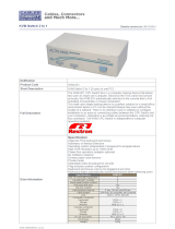
2.5 Technical specifications
Model No. 8 port PS/2 IP-KVM
switch
16 port PS/2 IP-KVM
switch
32 port PS/2 IP-KVM
switch
PC Port 8 16 32
Console Port 1
PC Port Connector
(All Female Types)
VGA HDDB 15-pin(shared with PS/2 keyboard and Mouse)
Console Port
Connector
(All Female Types)
Local Console: PS/2 Keyboard Mini Din 6 pin
PS/2 Mouse Mini Din 6 pin
VGA HDDB 15pin
Remote Console: RJ-45 8P8C
Daisy Chain Port
Connector
(All Female Types)
PS/2 Keyboard mini Din 6 pin
PS/2 Mouse Mini Din 6 pin
VGA HDDB 15pin
Serial Port (DB9 pin
Male)
1
LAN port (RJ-45 8P8C) 1
10BASE-T Ethernet uses Category 3/4/5/5E/6 UTP
100BASE-T Ethernet uses Category 5/5E/6 UTP
Reset port 1
PC selection On Screen Display Menu, Hot Key, Push Button
PC Port LED 8 16 32
Bank 7 segment LED 1
On Screen Display
Control
Yes
Scan Intervals 5~99 Sec.
Keyboard Emulation PS/2
Mouse Emulation PS/2
VGA Resolution Local Console: 1920X1440
Remote Console: 1280 X1024
Daisy Chain MAX
Level
8 levels
MAX PC Connection 232 240 256
Housing Metal
Power Adapter DC 5V, 2.5A
Operation Temperature
0~50
Storage Temperature
-20 ~ 60
Humidity 0~80%, Non-Condensing
Size 19” Rack Mount / 1RU 19” Rack Mount / 1RU 19” Rack Mount/ 2RU
Weight (kg) 2.0kg 2.2kg 3.5kg
Dimension (cm)
41(L) X 16.4(W) X 4.6(H) 41(L) X 16.4(W) X 4.5(H)
41(L) X 16.4(W) X 9(H
)

8/16/32 PS/2 KVM over IP switch
11
2.6 System requirement
Model No. 8 ports PS/2 IP-KVM switch
Local console side One VGA Monitor
One Keyboard
One Mouse
Network Side 10/100Mbps Ethernet
or Modem
Remote Console
side
One computer
Computer side 8 PCs with 8 3-in-one cables (One
HDDB 15-pin male to one HDDB 15-pin
and two Mini Din 6-pin PS2 cables)
Model No. 16 ports PS/2 IP-KVM switch
Console side One VGA Monitor
One Keyboard
One Mouse
Network Side 10/100Mbps Ethernet
or Modem
Remote Console
side
One computer
Computer side 16 PCs with 16 3-in-one cables (One
HDDB 15-pin male to one HDDB 15-pin
and two Mini Din 6-pin PS2 cables)
Model No. 32 ports PS/2 IP-KVM switch
Console side One VGA Monitor
One Keyboard
One Mouse
Network Side 10/100Mbps Ethernet
Or Modem
Remote Console
side
One computer
Computer side 32 PCs with 32 3-in-one cables (One
HDDB 15-pin male to one HDDB 15-pin
and two Mini Din 6-pin PS2 cables)
2.7 Cable diagrams
PS/2 Cable:
Mini Din 6 pin Male to Male

8/16/32 PS/2 KVM over IP switch
12
VGA Cable:
HDB15 pin Male to Male
AT to PS/2 keyboard adapter: (Optional)
Din 5 pin Male to Mini Din 6 pin Female
PS/2 to DB9 adapter (Optional)
Mini Din 6 pin Female to DB 9 pin Female
CAT5/5E/6 Straight Through UTP/STP Cable:
8P8C
2.8 Product Details
8 port Rack Mount PS/2 IP-KVM switch:
16 port Rack Mount PS/2 IP-KVM switch:
32 port Rack Mount PS/2 IP-KVM switch:

8/16/32 PS/2 KVM over IP switch
13

8/16/32 PS/2 KVM over IP switch
14
3. Hardware installation
3.1 Operation Overview
Figure 3.1 shows the connections of PS/2 IP-KVM switch to its host, to peripheral devices, to the
power source and to the local area network.
Figure 3.1: PS/2 IP-KVM switch usage scenario
PS/2 IP-KVM switch redirects local keyboard, mouse, and video data to a remote administration
console. All data is transmitted via IP.
PS/2 IP-KVM switch can be used in a multi administrator and multi server environment as well.
Attaching one PS/2 IP-KVM switch to a KVM switch or several PS/2 IP-KVM switch to a matrix KVM
switch allows accessing multiple servers on a single remote console.
3.2 Connecting PS/2 IP-KVM switch to the host system
Before installation, please make sure all of peripherals and computers have been turned off. This
example of installation is based on 8 port Rack Mount PS/2 IP-KVM switch and you also can think that
16 port Rack Mount PS/2 IP-KVM switch and 32 port Rack Mount PS/2 IP-KVM switch have the same
installation procedure. In order to connect the PS/2 IP-KVM switch to the host system, please perform
the following steps:
Step 1
Find a convenient place to put your PS/2 IP-KVM switch. Its 19” rack mount form factor makes it ideal
mountable on 19” rack. When mounting to a rack, attach the included brackets to the sides of the PS/2
IP-KVM switch. Take note of the length of your cables so that your computers, KVM Switch, keyboard,
mouse and monitor are distanced properly.
Administrator
IP Network 8/16 PS/2
KVM
8/16 Servers

8/16/32 PS/2 KVM over IP switch
15
Step 2 (Local console)
Connect the monitor to the KVM Switch. Using the attached cable, or the one included with your
monitor, connect it to the HDDB15-pin female port on the back of the KVM unit labeled with the
monitor symbol at the CONSOLE connector.
Step 3
Connect the keyboard to the KVM Switch. If you have an AT type keyboard, you will need an AT to
PS/2 adapter.
Step 4
Connect the mouse to the KVM Switch.
Step 5
Each PC port connector is HDDB15-pin type. Locate your input cable. It will have an HDDB15-pin
male connector at one end. Plug it into any label computer port on the rear of KVM switch unit. The
other end of input cable will have three connectors: a HDDB15-pin male type for PC video, a Mini Din
6 pin female type for keyboard and a Mini Din 6 pin female type for mouse. To plug these three
connectors into the respective ports of computer. Repeat the same procedure to all of PCs.

8/16/32 PS/2 KVM over IP switch
16
Step 6 (Optional)
If using a serial mouse cable (optional), connect one end to a DB-9 serial port on the computer, and
the other Mini Din 6 pin end to the mouse cable connector. If you need Serial DB-9 to PS/2 Mini Din 6
pin adapter, please contact your supplier.
Step 7
Double-check all of the connections. You can check the color of keyboard and mouse connector to
make sure the keyboard and mouse cables go to the correct ports.
Step 8
Repeat step 5 to 7 for the remainder of the computers.
Step 9
Connect the Ethernet and/or modem, ISDN, depending how you want to access PS/2 IP-KVM switch.
The rear side of PS/2 IP-KVM switch provides a RJ-45 connector for Ethernet. The connector is used
either for a 100 Mbps 100BASE-TX connection or for a 10 Mbps 10BASE-T connection. The adapter
can sense the connection speed and will adjust to the appropriate operation mode automatically.
10 Mbps Connection
The Rear Side of
INTERNET
Mode

8/16/32 PS/2 KVM over IP switch
17
For 10BASE-T Ethernet networks, the Fast Ethernet adapter uses Category 3, 4, or 5 UTP
cable. To establish a 10 Mbps connection, the cable must be connected to a 10BASE-T
hub.
¾ Make sure that the cable is wired appropriately for a standard 10BASE-T adapter.
¾ Align the RJ-45 plug with the notch on the adapter’s connector and insert it into the
adapter’s connector.
100 Mbps Connection
For 100BASE-TX Fast Ethernet networks, PS/2 IP-KVM switch supports Category 5 UTP
cabling. To establish a 100 Mbps connection, the cable must be connected to a
100BASE-TX hub.
¾ Make sure that the cable is wired appropriately for a standard 100BASE-TX adapter.
¾ Align the RJ-45 plug with the notch on the adapter’s connector and insert it into the adapter’s
connector.
¾
Step 10
Attach the power supply to the KVM unit and plug the other end into an electrical receptacle.
3.2.1 Connecting the External Reset/Power Option
Please refer to the manual of the PS/2 IP-KVM switch 8/16/32 port external power switch option or a
third party external power option to connect those external devices to one of the serial interface on the
rear side of PS/2 IP-KVM switch. By the date of printing this manual supported options are:
¾ . Avocent.SPC1 800/1600
¾ . Sentry In-Line Power Module
¾ . Leaning ePowerSwitch
¾ Peppercon IPM-220L

8/16/32 PS/2 KVM over IP switch
18
4. Configuration
4.1 Initial Configuration
The PS/2 IP-KVM switch's communication interfaces are all based on TCP/IP. It comes
pre-configured with the IP configuration listed in Table 4-1.
Parameter Value
IP auto configuration DHCP
IP-Address -
Net-mask 255.255.255.0
Default-Gateway none
Table 4-1. Initial network configuration
Warning
If the DHCP connection fails on boot up, the PS/2 IP-KVM switch will not have an IP
address.
If this initial configuration does not meet your requirements, the following describes the initial IP
configuration that is necessary to access the PS/2 IP-KVM switch for the first time.
4.1.1 Initial configuration via DHCP server
By default, the PS/2 IP-KVM switch will try to contact a DHCP server in the subnet to which it is
physically connected. If a DHCP server is found, it may provide a valid IP address, gateway
address and net mask. Before you connect the device to your local subnet, be sure to complete
the corresponding configuration of your DHCP server. It is recommended to configure a fixed IP
assignment to the MAC address of the PS/2 IP-KVM switch. You can find the MAC address
labeled on the bottom side.
If this initial configuration does not meet your local requirements, use the setup tool to adjust the
values to your needs. The setup tool can be found on the CD ROM delivered with this package.
You can follow the procedure described below.
PS/2 IP-KVM switch Setup Tool
MAC Address Detection
Connect the PS/2 IP-KVM switch to your computer either via local network, or via USB. Start
the setup tool from the CD ROM on the computer that the PS/2 IP-KVM switch is installed.
Depending on the connection (USB or network), the device detection is different. A window
opens as seen below:

8/16/32 PS/2 KVM over IP switch
19
Figure4-1. PS/2 IP-KVM switch setup tool
On the upper left corner, the MAC address of the PS/2 IP-KVM switch is displayed. To detect
the MAC address, manually, press the button “Refresh Devices”. The displayed MAC address
is the same MAC address printed on the white sticker placed on the back of the PS/2 IP-KVM
switch. If the PS/2 IP-KVM switch is connected via USB, it is classified as an USB device and
an appropriate drive letter is chosen for this device.
On the lower right corner of the window, there are two buttons: “Query Device” and “Setup
Device“. Press the “Query Device” button to display the preconfigured values of the network
configuration. The values are displayed in the text fields located above. If necessary, adjust the
network settings to your needs. To save the changes, press the “ Setup Device ” button.
Authentication
To adjust the authentication settings, enter your login as a super user, and change your
password.
Super user login
Enter the login name of the super user. The initial value is “ super ”. All of characters are
lower case.
Super user password
Enter the current password for the super user. This initial value is “ pass “. All of characters
are lower case.
New super user password
Enter the new password for the super user.
New password (confirm)
Re-type the new password for the super user.
To close the window and accept the changes, press the “ OK ” button, otherwise press the
“ Cancel ” button.

8/16/32 PS/2 KVM over IP switch
20
4.1.2 Initial configuration via serial console
Using a serial terminal, the PS/2 IP-KVM switch has a serial line interface (rear side). This
connector is compliant with the RS 232 serial line standard. The serial line has to be configured
with the parameters given in Table 4-2.
When configuring with a serial terminal, reset the PS/2 IP-KVM switch and immediately press the
“ESC” key. You will see some device information, and a “=>” prompt. Enter “config”, press “Enter”
and wait for a few seconds for the configuration questions to appear.
Parameter Value
Bits/second 115200
Data bits 8
Parity No
Stop bits 1
Flow Control None
Table 4-2. Serial line parameters
As you proceed, the following questions will appear on the screen. To accept the default values
which are shown in square brackets below, press “Enter”.
IP auto configuration (non/dhcp/bootp) [dhcp]:
IP [192.168.1.22]:
Net mask [255.255.255.0]:
Gateway (0.0.0.0 for none) [0.0.0.0]:
IP autoconfiguration
With this option, you can specify whether the PS/2 IP-KVM switch should get its network
settings from a DHCP or BOOTP server. For DHCP, enter “dhcp“, and for BOOTP enter “bootp“.
If you do not specify any of these, the IP autoconfiguration is disabled and subsequently you will
be asked for the following network settings.
IP address
The IP address the PS/2 IP-KVM switch uses. This option is only available if IP
autoconfiguration is disabled.
Net mask
The net mask of the connected IP subnet. This option is only available if IP autoconfiguration
is disabled.
Gateway address
The IP address of the default router for the connected IP subnet. If you do not have a default
router, enter 0.0.0.0. This option is only available if IP autoconfiguration is disabled.
4.1.3 Keyboard, Mouse and Video configuration
Between the PS/2 IP-KVM switch and the host, there are two interfaces available for transmitting
keyboard and mouse data: USB and PS/2. The correct operation of the remote mouse depends
on several settings, which will be discussed in the following subsections.
/