Aero Pure ABF80 G15 SN Installation guide

Type
Installation guide
BATH FAN
READ AND SAVE THESE INSTRUCTIONS
Thank you very much for purchasing our bath fan.
Please read the instructions carefully before attempting
to install, operate, or service our bath fan. Failure to comply
with instructions could result in personal injury or property
damage. Please retain this booklet for future reference.
INSTALLATION INSTRUCTIONS
...............................................................................................................
.......................................................................................
...........................................................................................................
.........................................................................
.............................................................................................................
....................................................................................................
..............................................................
..................................................................................
....................................................................................
...................................................................
......................................................................................................
...............................................................................................................
TABLE OF CONTENTS
UNPACKING
SUPPLIED ACCESSORIES
DESCRIPTION
GENERAL SAFETY INFORMATION
DIMENSIONS
WIRING DIAGRAM
INSTALLATION
I (NEW CONSTRUCTION)
INSTALLATION
II (RETROFIT
MAINTENANCE (CLEANING)
PRACTICAL GUIDE TO INSTALLATION
SPECIFICATIONS
WARRANTY
02
02
02
03
04
04
05
08
09
10
11
12
Model No.
ABF80L5 Series
ABF110L5 Series
ABF80G16 Series
ABF110G16 Series
ABF80L6 Series
ABF110L6 Series
ABF80G15 Series
ABF110G15 Series
ABF80G1 Series
ABF110G1 Series
ABF80L1 Series
ABF110L1 Series
UNPACKING
Unpack and carefully remove the unit from carton.
Refer to the supplied accessories list to verify that all parts are present.
SUPPLIED ACCESSORIES
DESCRIPTION
2
1
5
1
Installation
instructions
Suspension
bracket
assembly
Grille
Long screw
(ST4X30)
or oror
These bath fan models are listed by ETL under ETL file No.5011292.
These bath fan models use a Sirocco fan driven by a capacitor motor.
The motor is designed to have an extended service life with reduced energy consumption.
The motor incorporates a thermal-cutoff for safety. The grille covering the fan body is a spring-loaded,
quick attach type. A damper for preventing air counterflow is provided.
The suspension bracket assembly can be used for both new and retrofit construction.
The light uses a bright SMD LED.
1
Wire
Protector
Nut
G15 G16 L5 L6 G1 L1
or
or
Use this unit only in the manner intended by the manufacturer. If you have any questions, contact
the manufacturer.
Before servicing or cleaning unit, switch power off at service panel and lock the service
disconnecting means to prevent power from being switched on accidentally. When the service
disconnecting means cannot be locked, securely fasten a prominent warning device, such as a
tag, to the service panel.
Installation work and electrical wiring must be done by qualified person(s) in accordance with
all applicable codes and standards, including fire-rated construction.
Sufficient air is needed for proper combusition and exhausting of gases through the flue (chimney)
of fuel burning equipment to prevent back drafting. Follow the heating equipment manufacture′s
guideline and safety standards such as those published by the National Fire Protection Associa-
tion (NFPA), and the American Society of Heating, Refrigration, and air conditioning Engneers
(ASHRAE) and the local code authorities.
When cutting or drilling into wall or ceiling, do not damage electrical wiring and other hidden
utilities.
Ducted fans must always be vented to the outdoors.
If this unit is to be installed over a tub or shower, it must be marked as appropriate for the
application and be connected to a GFCI (Ground Fault Circuit Interrupter)-protected branch circuit.
These models are ETL listed for tub and shower enclosures.
Not to be installed in a celling thermally insulated to a value greater than R40. (This is required for
installation in Canada only).
Do not install this bath fan where interior room temperature may exceed
104°F (40°C).
To reduce the risk of fire, electric shock, or injury to persons, observe the following:
WARNING:
1.For general ventilating use only. Do not use to exhaust
hazardous or explosive materials and vapors.
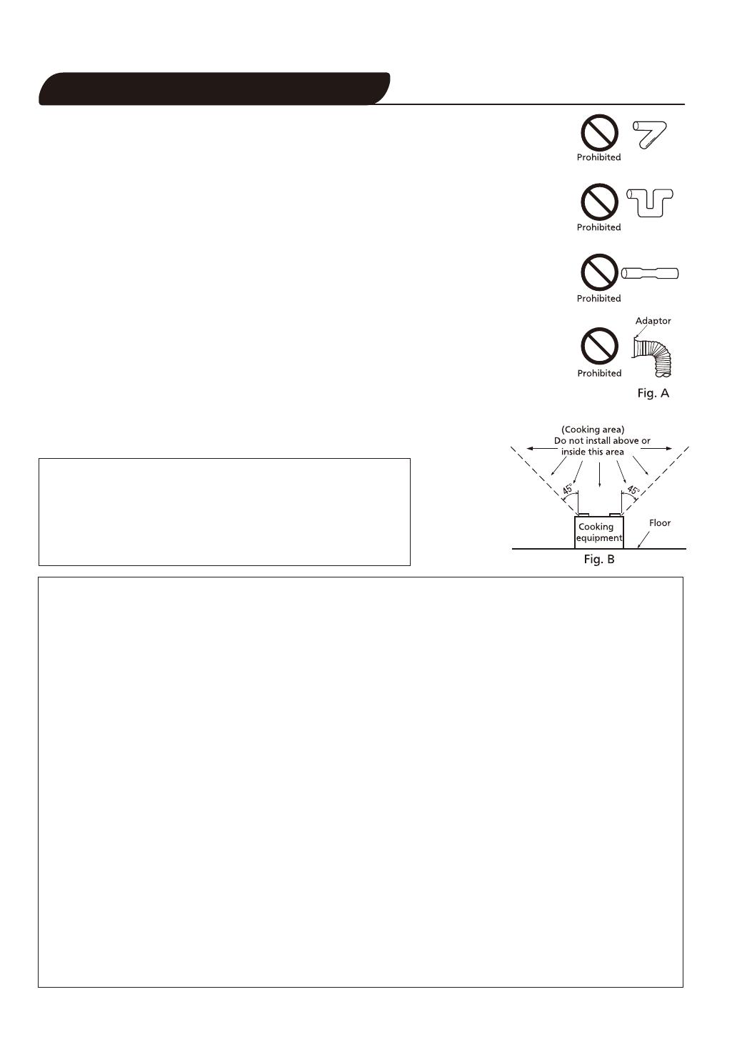
2.Not for use in cooking area. (Fig.B)
3.This product must be properly grounded.
CAUTION:
GENERAL SAFETY INFORMATION
Make sure that the electric service supply voltage is AC 120V, 60Hz.
Follow all local electrical and safety codes, as well as the National Electrical
Code (NEC), and the Occupation Safety and Health Act (OSHA).
Always disconnect the power source before working on or near the fan, motor,
light fixture, or junction box.
Protect the power cord from sharp edges, oil, grease, hot surfaces, chemicals,
or other objects.
Do not kink the power cord.
Do not install the unit where ducts are configured as shown in Fig.A.
Provide make up air for proper ventilation.
1.
2.
3.
4.
5.
6
7.
8.
1.
2.
3.
4.
5.
6.
7.
8.
9.
3
DIMENSIONS
WIRING DIAGRAM
7 1/3 (186)
3/5 (14.5)
3 7/8 (98)
4 7/8 (123)
5 4/5 (147)
3 4/5 (97)10 2/5 (265)
Motor
Ground
Live
Neutral
Green
Black
White
C
Motor
Light Body
Blue
Brown
White
Live (Light)
Live (N. Light)
Neutral
Ground
Live
Neutral
Green
Black
White
C
Fan only model: With light model:
4
Unit: inches (mm)
Fan body
Fan body
10 1/4 (260)
12 1/8 (308)
13 (330)
Knock-out plate
Junction box
Capacitance box
Bracket assembly
LED light
Blade
Grille
Adaptor
Damper
Fan body
1
2
3
4
5
6
7
8
9
10
Series: ABF80G15, ABF110G15, ABF80G16, ABF110G16, ABF110G1
ABF80L5, ABF110L5, ABF80L6, ABF110L6, ABF110L1
INSTALLATION I(NEW CONSTRUCTION)
Fix one side of the bracket assembly to the joists by
drilling 2 tapping screws (ST4x20) which have been
fixed on it. Fig.3
Adjust the length of bracket assembly as the
spacing between joists, and install to joist by drilling
the other 2 tapping screws which have been fixed
on the other side. Adjust the active part of bracket
assembly to the proper position. (Fig.3
Tab
Fig.2.a
Fig.2.b
IMPORTANT:
Remove the tape from damper and adaptor
before installation. As shown below:
Fig.4
Fig.3
Joist
Screws
(ST4X20)
2 screws
(ST4X30)
Place the adaptor on the bracket assembly as
indicated position and install it by using 2
self-drilling screws (ST4X30). (Fig.4)
Unit: inches (mm)
5
Fig.1
Two cases of spacing L :
L
Joist situation:
12 inches (305 mm)
16~24 inches (406~610 mm)
A
B
If the spacing L is 16~24 inches (406~610 mm),
use the suspension bracket assembly.
Bend down 8 tabs for positioning as (Fig.2.a) and
unfold the bracket assembly as (Fig.2.b).
If the spacing L is 12 inches (305 mm) on joists,
please follow the installation step as (Fig.1).
Secure 4 screws (ST4X30) at flange of frame to the
joists. Then follow steps 6 to 9 of Installation
I
(page 6-8) to complete the installation.
Please wear gloves during the installation work.
CAUTION:
11 4/5~22 1/2 (300~579)
4 screws
(ST4x30)
A
B
1.
2.
3.
4.
Active part
Position
of adaptor
Fig.5
Push the fan body upwards until the fan body is
stopped by the buckle on the adapter and secure
the fan body by using the remaining 3 self-drilling
screws (ST4X30). (Fig.5)
6
Fig.7
Attach cable clamp to knock-out
plate.Knock-out plate mounts to
outside of housing and may be
positioned as desired.
Connect
wires
Nuts
Screw from
Parts Bag
II
III
IV
Install a circular duct and secure it with clamps
or ties and seal it with mastic or approved duct tape.
A 4 5” or 6” circular duct is needed to connect
to relevant part of adaptor. (Fig.6)
Fig.6
Circular duct
Duct tape
INSTALLATION I(NEW CONSTRUCTION) CONTINUED
Hold the fan body to prevent falling before fixing
the screws.
CAUTION:
Buckle
Fan body
3 Screws
(ST4x30)
5.
6.
Remove the knock-out plate and secure conduit
or wire protector nut to knock-out hole. (Fig.7.
I )
7.
Refer to wiring diagram on page 4.
Using UL approved wire nuts, connect house power
wires to the ventilating fan wires (Fig.7.
II ), then
attach it to fan body.
Follow all the local eletrical safety codes as well
as the National Electrical Code (NEC).
IMPORTANT:
I
Mount grille carefully so the lead wire of light
unit is not pinched.
Fig.11
Fig.8
Insert mounting springs into slots and mount grille
to fan body.Fig.9
Grille
Celling
Slot
Mounting spring
Fig.9
Finsh ceiling work. Align ceiling hole with the inside
edges of the flange. (Fig.8)
After finishing the celling work, fill gap between
flange and celling with caulk or other sealant to
prevent air leakage.
Caulk
IMPORTANT:
Unit: inches (mm)
7
Before turning on the light, make sure the
connector is at the correct position. If not,
the lighting will not work.
The claw of connector must be secured to
the rib completely. (Fig.10)
1.
2.
Fig.10
For grille with a lightrefer to the following
installation method.
Insert the grille mounting spring on the wiring side
into the slot. (Fig.10)
Insert the plug connector into the housing of the
lighting unit and insert other mounting spring into
the slot as shown and mount grille to fan body.
(Fig.10, Fig.11)
10 2/5 (265)
10 2/5 (265)
Celling
INSTALLATION I(NEW CONSTRUCTION)CONTINUED
CAUTION:
CAUTION:
8.
9.
8
Fig.14
3.
Screw from
Parts Bag
Attach cable clamp to Knockout
Plate.Knockout Plate mounts to
outside of Housing and may be
positioned as desired.
Connect
wires
INSTALLATION II (RETROFIT)
Put the folded bracket assembly into ceiling hole,
then follow step 3-4 of Installation
I (NEW
CONSTRUCTION page 5) to complete the bracket
installation. (Fig.12)
2.
1.
Screws
(ST4x30)
Unit:inches(mm)
Unit: inches (mm)
Fig.12
Fig.13
A
B
screws
(ST4x20)
10 3/5(270)
10 3/5(270)
Follow step 4 of Installation I (NEW
CONSTRUCTION page 5) to complete the
adaptor installation. (Fig.13)
Install a circular duct and secure with clamps
or ties and seal with mastic or approved foil tape.
A 4”, 5”or 6” circular duct is needed to connect
to relevant part of adaptor. (Fig.13)
Remove the knock-out plate and secure conduit
or wire protector nut to knock-out hole. (Fig.14)
Refer to wiring diagram on page 4.
Using UL approved wire nuts, connect house power
wires to the ventilating fan wires (Fig.14), then
attach it to fan body.
Follow all the local eletrical safety codes as well
as the National Electrical Code (NEC).
IMPORTANT:
MAINTENANCE (CLEANING)
1.
Disconnect power source before working on unit.
Routine maintenance must be done every year.
WARNING:
Fig.16
3.
2.
Fig.17
Clean grille. (Don’t put into hot water. Use
non-abrasive kitchen detergent then wipe dry with
clean cloth). (Fig.17)
The grille should be dry after cleaning before
reattaching to fan motor.
1.
2.
3.
CAUTION:
Grille
INSTALLATION II (RETROFIT)CONTINUED
Fig.15
4.
5.
9
Follow step 9 of Installation I (NEW
CONSTRUCTION page 7) to complete installation.
Push the fan body upwards until the fan body is
secure with the joint, and secure them by using the
remaining 3 self-drilling screws(ST4X30) (Fig.15)
3 Screws
(ST4x30)
Never use gasoline, benzene, thinner, or any
other such chemicals for cleaning the ventilating
fan.
Do not immerse motor in water when cleaning.
Do not soak resin parts in water over 140°F
(60°C).
Remove grille. (Squeeze mounting spring and
pull down carefully). (Fig.16)
MAINTENANCE (CLEANING) CONTINUED
4.
Fig.18
5.
6. Reinstall grille.
Fig.19
lnsulation
Fig.20
Properly insulate the area around the
fan to minimize building heat loss and
gain. (Fig.20)
Loose fill or batt insulation can be
placed directly over the fan housing in
the attic.
The fans and fan/light combination units
do not create excessive heat that is a
common problem with recessed light
fixtures or some competitors′ fan/light
combinations. Our efficient, cool-running
motors,
and LED lighting unit do not
create enough ambient heat to be subjected to these limitations.
PRACTICAL GUIDE TO INSTALLATION
Foil tape tightly covers all metal
duct joints (glue PVC joints)
4 inches or 6 inches roof jack, wall cap,
or soffit vent with backdraft damper
Mechanically connect duct to termination
and seal with mastic or approved foil
faced tape
2-3 ft straight run before elbow
ln attic installation,
caulk box to drywall
Short piece of flexible duct helps
alignment and absorbs sound.
Clamps plus mastic or approved
foil faced tape at all flex joints
The ducting from this fan to the outside of the building has a strong effect on the air flow, noise, and energy
use of the fan. Using the shortest, straightest duct routing possible for best performance, and avoid
installing the fan with smaller ducts than recommended. Insulation around the ducts may reduce energy
loss and inhibit mold growth. Fans installed with existing ducts may not achieve their rated air flow.
10
Remove dust and dirt from fan body using a
vacuum cleaner. (Fig.18)
Using a cloth dampened with kitchen detergent,
remove any dirt from fan body then wipe dry with
clean cloth. (Fig.19)
Power
consumption (W)
Fan Light N.Light
ABF80G15OR
ABF80G15SN
ABF80G15W
ABF80G16OR
ABF80G16SN
ABF80G16W
ABF110G15OR
ABF110G15SN
ABF110G15W
ABF110G16OR
ABF110G16SN
ABF110G16W
ABF80L5OR
ABF80L5SN
ABF80L5W
ABF80L6OR
ABF80L6SN
ABF80L6W
ABF110L5OR
ABF110L5SN
ABF110L5W
ABF110L6OR
ABF110L6SN
ABF110L6W
849
849
1140
1140
928
928
1080
1080
80
80
110
110
80
80
110
110
18.7
18.7
25.2
25.2
18.4
18.4
25.6
25.6
10
10
10
10
0.7
0.7
0.7
0.7
Model No.
Speed
(rpm)
Air volume
at 0.1"WG
(CFM)
SPECIFICATIONS
Exhaust
Exhaust
Exhaust
Exhaust
Exhaust
Exhaust
Exhaust
Exhaust
120
120
120
120
120
120
120
120
60
60
60
60
60
60
60
60
4′′, 5′′, 6′′
4′′, 5′′, 6′′
4′′, 5′′, 6′′
4′′, 5′′, 6′′
4′′, 5′′, 6′′
4′′, 5′′, 6′′
4′′, 5′′, 6′′
4′′, 5′′, 6′′
0.4
0.4
1.1
1.1
0.3
0.3
0.9
0.9
Air
direction
Frequency
(Hz)
Voltage
(V)
Noise
(sones)
Duct
diameter
(inches)
11
ABF80G1W Exhaust 120 60 4”, 5”, 6” 0.4 18.7 849 80
ABF110G1W Exhaust 120 60 4”, 5”, 6” 1.1 25.2 1140 110
ABF80L1W Exhaust 120 60 4”, 5”, 6” 0.3 18.4 10 0.7 928 80
ABF110L1W Exhaust 120 60 4”, 5”, 6” 0.7 24.8 10 0.7 1020 110
This warranty covers all defects in workmanship or materials for:
The mechanical and electrical parts contained in this product for a period of 72 months from the date of
purchase. You must keep and be able to provide your original sales receipt as proof of date of purchase
from an authorized seller of Aero Pure Fans.
This warranty is covered to the original purchaser of this product only. The manufacturer will replace
any mechanical or electrical part that proves defective in normal household use for a period of 72 months.
THIS WARRANTY DOES NOT COVER:
• Damages from improper installation.
• Damages from shipping.
• Damages from misuse, abuse, accident, alteration, lack of proper care and maintenance.
• Damages from service by persons other than a licensed electrician.
• Does not cover any labor or transportation charges related to the repair of this product.
• Does not cover product purchased as used.
• Does not cover product purchased from an unauthorized seller of Aero Pure Fans.
THIS LIMITED WARRANTY IS GIVEN IN LIEU OF ALL OTHER WARRANTIES, EXPRESSED OR
IMPLIED, INCLUDING THE WARRANTIES OF MERCHANTABILITY AND FITNESS FOR A
PARTICULAR PURPOSE.
The remedy provided in this warranty is exclusive and is granted in lieu of all other remedies. This warranty
does not cover incidental or consequential damages. Some states do not allow the exclusion of incidental
or consequential damages, so this limitation may not apply to you.
Some states do not allow limitations on how long an implied warranty lasts, so this limitation may not apply
to you. This warranty gives you specific legal rights; you may also have other rights, which vary from state
to state.
All Aero Pure Fans MUST be installed by a licensed electrician. Otherwise warranty is null and void.
Aero Pure LLC
1006 Bankton Circle Building B
Hanahan, SC 29410
Tel: 843.377.8642
Fax: 843.377.8643
WEBSITE: WWW.AEROPUREFANS.COM
WARRANTY
12
  • Page 1 1
  • Page 2 2
  • Page 3 3
  • Page 4 4
  • Page 5 5
  • Page 6 6
  • Page 7 7
  • Page 8 8
  • Page 9 9
  • Page 10 10
  • Page 11 11
  • Page 12 12

Aero Pure ABF80 G15 SN Installation guide

Type
Installation guide

Ask a question and I''ll find the answer in the document

Finding information in a document is now easier with AI