Page 14
Ph: 804.227.3023
10511 Old Ridge Rd. Ashland, VA 23005
4LHD/4LHDX Application Manual
Powertrain Control Solutions
REV 1.1
Abuse Protection Solenoid (Electronic Range)
The two identical ER Forward/Reverse Abuse Protection solenoids are three port PWM (Pulse Width Modulation)
solenoids (normally closed).
• The ER Forward/Reverse solenoids operate at a xed frequency (negative duty cycle) of 32 Hz.
• The ER Forward/Reverse solenoids coil resistance should be 10.4-10.8 Ohms when measured at 20.0 +/- 5.0°C
• The ER Forward/Reverse solenoids coil resistance should be approximately 16 Ohms when measured at 150 +/-
5.0°C.
Pressure Control Solenoid
The Pressure Control Solenoid is a three port electronic pressure regulator used to control line pressure. When the
solenoid is off, line pressure is unrestricted from the line pressure pump. When the solenoid is on, line pressure is
restricted to the values shown in the chart. A line pressure tap is available. The torque rating for this tting is 8 lb*ft / 11
N*m. Reference Figure 2.4.6.1-3.
• The Pressure Control Solenoid operates at a xed frequency of 292.5 Hz.
• The Pressure Control Solenoid coil resistance is 3.5-4.6 Ohms at 20.0 +/- 5.0°C.
Abuse Protection Solenoid (Non-Electronic Range)
The identical Forward/Reverse Abuse Protection Solenoids (Non-ER) three port linear pressure control solenoids
(normally open).
• The Non-ER Forward/Reverse solenoids coil resistance is 5.0-5.6 ohms at 25.0 +/- 1.0°C.
• The Non-ER Forward/Reverse solenoids operate at a xed frequency of 300Hz.
42
PRESSURE CONTROL SOLENOID VALVE CURRENT FLOW
➤
TIME
VOLTS
12
0
1 CYCLE = 1/292.5 SECOND
➤
➤
40%
60%
➤
➤
➤
➤
➤
(ON)
PRESSURE CONTROL SOLENOID VALVE POSITIVE DUTY CYCLE
PRESSURE CONTROL SOLENOID VALVE
➤
➤
➤
➤
➤
➤
➤
➤ ➤ ➤
➤
➤ ➤ ➤
➤
➤
➤
➤
➤
➤ ➤ ➤ ➤
➤
➤
➤
➤
➤
➤
➤
PUSH
ROD
FRAMESPRING
SPOOL
VALVE
ACTUATOR
FEED
LIMIT
FLUID
TORQUE
SIGNAL
FLUID
COIL
ASSEMBLY
EXHAUST ARMATURE
DAMPER
SPRING
FLUID
SCREENS
SPOOL
VALVE
SPRING
VARIABLE
BLEED
ORIFICE
SPOOL
VALVE
SLEEVE
0.0
0.1 0.2 0.3 0.4
0.60.5 0.7 0.8 0.9
1.0 1.1
INPUT CURRENT (AMP)
0
CONTROL PRESSURE (PSI)
10
20
30
40
50
60
70
80
90
100
ELECTRICAL COMPONENTS
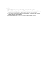
Figure 40
Pressure Control Solenoid Valve
The pressure control (PC) solenoid valve is a precision electronic
pressure regulator that controls transmission line pressure based
on current flow through its coil windings. As current flow is
increased, the magnetic field produced by the coil moves the
solenoid’s plunger further away from the exhaust port. Opening
the exhaust port decreases the output fluid pressure regulated by
the PC solenoid valve, which ultimately decreases line pressure.
The PCM controls the PC solenoid valve based on various
inputs including throttle position, transmission fluid temperature,
MAP sensor and gear state.
Duty Cycle, Frequency and Current Flow
A “duty cycle” may be defined as the percent of time current is
flowing through a solenoid coil during each cycle. The number of
cycles that occur within a specified amount of time, usually
measured in seconds, is called “frequency”. Typically, the operation
of an electronically controlled pulse width modulated solenoid is
explained in terms of duty cycle and frequency.
The PCM controls the PC solenoid valve on a positive duty
cycle at a fixed frequency of 292.5 Hz (cycles per
second). A
higher duty cycle provides a greater current flow through the
solenoid. The high (positive) side of the PC solenoid valve
electrical circuit at the PCM controls the PC solenoid valve
operation. The PCM provides a ground path for the circuit,
monitors average current and continuously varies the PC solenoid
valve duty cycle to maintain the correct average current flowing
through the PC solenoid valve.
Approximate
Duty Cycle Current Line Pressure
+ 5% 0.1 Amps Maximum
+40% 1.1 Amps Minimum
Pressure control solenoid valve resistance should measure
between 3.5 and 4.6 ohms when measured at 20
°C (68°F).
The duty cycle and current flow to the PC solenoid valve are
mainly affected by throttle position (engine torque) and they are
inversely proportional to throttle angle (engine torque). In other
words, as the throttle angle (engine torque increases), the duty
cycle is decreased by the PCM which decreases current flow to the
PC solenoid valve. Current flow to the PC solenoid valve creates
a magnetic field that moves the solenoid armature toward
the push
rod and against spring force.
Transmission Adapt Function:
Programming within the PCM also allows for automatic
adjustments in shift pressure that are based on the changing
characteristics of the transmission components. As the apply
components within the transmission wear, shift time (time required
to apply a clutc
h or band) increases. In order to compensate for
this wear, the PCM adjusts trim pressure by controlling the PC
solenoid valve in order to maintain the originally calibrated shift
timing. The automatic adjusting process is referred to as “adaptive
learning” and it is used to assure consistent shift feel plus increase
transmission durability. The PCM monitors the A/T ISS sensor
and A/T OSS during commanded shifts to determine if a shift is
occurring too fast (harsh) or too slow
(soft) and adjusts the PC
solenoid valve signal to maintain a set shift feel.
A Pressure Control Solenoid electrical problem will set a DTC
P0748 and the PCM will command the following default actions:
• Disable the PC solenoid valve.
• Freeze shift adapts.
• DTC P0748 stores in PCM history.
Transmission adapts must be reset whenever the transmission is
overhauled or replaced (see appropriate service manual).
Figure 1.5.1-2: Pressure Control Solenoid Valve Current Flow
52
ELECTRICAL COMPONENTS
Figure 46
SHIFT PRESSURE CONTROL SOLENOID VALVE CURRENT FLOW
PLNGR
54
54
54
21
CNTRL
PRESS
SHIFT
20
21
9
54
54
54
54 54
SHIFT
PRESSURE CONTROL
SOLENOID VALVE
(SLS) (340)
1111
11
FLUID PRESSURE
TEST HOLE PLUG (334)
INPUT CURRENT (AMP)
CONTROL PRESSURE (PSI)
0.0
0.1 0.2 0.3 0.4
0.60.5 0.7 0.8 0.9
1.0 1.1
0
20
40
60
80
160
100
120
140
SHIFT PRESSURE CONTROL SOLENOID VALVE (SLS)
EXHAUST
EXHAUST
CONNECTOR
COIL
ASSEMBLY
SPOOL
VALVE
SPRING
PLUNGER
PRESSURE
SUPPLY
(SOLENOID
MODULATOR)
PRESSURE
CONTROL
(SHIFT
CONTROL)
HOUSING SPOOL
VALVE
Shift Pressure Control Solenoid Valve (SLS) (340)
The shift pressure control solenoid valve (normally-open, 3-port
linear pressure control solenoid) is a precision electronic pressure
regulator that controls transmission clutch apply pressure based
on current flow through its coil windings. As current flow is
increased, the magnetic field produced by the coil moves the
solenoid’s plunger further away from the exhaust port. Opening
the exhaust port decreases the output fluid pressure regulated by
the shift pressure control solenoid valve, which ultimately
decreases clutch apply pressure. The TCM controls the shift
pressure control solenoid valve based on various inputs including
throttle position, transmission fluid temperature and gear state.
Shift pressure control solenoid valve resistance should
measure between 5.0 and 5.6 ohms when measured at
20
°C (68°F).
The shift pressure control solenoid valve operates at a fixed
frequency of 300 Hz (cycles per second). The supply current to
the shift pressure control solenoid valve is mainly affected by
throttle position (engine torque), and is inversely proportional to
throttle angle (engine torque). In other words, as the throttle
angle (engine torque)
increases, the TCM decreases the supply
current to the shift pressure control solenoid valve. Current flow
to the shift pressure control solenoid valve
creates a magnetic
field that moves the solenoid plunger against spring force.
Transmission Adapt Function
Programming within the TCM also allows for automatic
adjustments in shift pressure that are based on the changing
characteristics of the transmission components. As the apply
components within the transmission wear, shift time (the time
required to apply a clutch) increases. In order to compensate for
this wear, the TCM adjusts trim pressure by controlling the shift
pressure control solenoid valve in order to maintain the originally
calibrated shift timing. The automatic adjusting process is
referred to as “adaptive learning” and it is used to assure
consistent shift feel plus increase transmission durability. The
TCM monitors the A/T ISS and the A/T OSS during commanded
shifts to determine if a shift is occurring too fast (harsh) or too
slow (soft) and adjusts the shift pressure control solenoid valve
signal to maintain a set shift feel.
Transmission adapts must be reset whenever the transmission
is overhauled or replaced (see appropriate service manual).
A Shift Pressure Control Solenoid Valve electrical
malfunction will set a DTC P0970 or P0971 and the TCM
will command the following default actions:
• Disable the shift pressure control solenoid valve.
• Freeze shift adapts.
• DTC P0970 or P0971 stores in TCM history.
Figure 1.5.1-1: Abuse Protection Solenoid Valve Current Flow