Page is loading ...

NECTA SPA TECHNICAL MANUAL “ Snakky “
Manual Snakky 1 / 23
AFTER SALES SERVICE food & snack
SERVICE MANUAL
“ SNAKKY ”
BASIC TECHNICAL MANUAL
THE CONTENTS OF THIS DOCUMENT ARE INTENDED FOR NECTA’S AFTER SALES PERSONNEL.

NECTA SPA TECHNICAL MANUAL “ Snakky “
Manual Snakky 2 / 23
NOTE
The above systems and functional units are specific to this machine.
All functional units installed but not listed in this document, are also used in other machines in the same range; therefore they
will be described in a separate manual for machines belonging to the same range, where all base functional units will be
described more in detail.
Snakky:
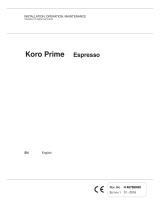
View of user interface
TABLE OF CONTENTS
1
2
3
4
5
6
7
8
9
10
11
12
Layout - Models
Electrical systems, connections and configuration
Release - dispensing - storage systems
Wiring
Power supply
Cooling unit
Cabinet
Door
Wiring diagrams
Trouble-shooting
HACCP directive (Use instructions)
Periodical cleaning and hygiene
Page 3/4
Pages 5/6/7/8/9
Pages 10
Page 11
Page 12
Pages 13
Page 14
Page 15
Page 16/17/18
Pages 19/20
Page 21
Pages 22/23
Reference
Description
1 Door opening frame
2 Advertising spaces
3 Provision for bill accepters
4 Machine status information display
5 Provision for key-type payment
systems
6 Coin slot
7 Key lock
8 Selection keypad
9 Glass door
10 Coin return compartment
11 Product dispensing compartment
6
2
8
4

NECTA SPA TECHNICAL MANUAL “ Snakky “
Manual Snakky 3 / 23
1 – LAYOUT - MODELS
Layout Italy - Version 6-30R / I Q
Meaning:
Snakky
with 6 trays for a total of 30 selections
Refrigerated version R (a non refrigerated version is also available)
Country: Italy I
Approved by IMQ Q (if the letter Q is not present it means that such version is not approved by IMQ, or that it is awaiting
approval
DESCRIPTION VARIABLES
TRAYS Up to 6 max
HEIGHT 0F TRAYS 96 mm min and up to 219 mm max
PARTITIONS PER TRAY 2 triple - 3 double - 6 single
PRICES PER TRAY One for each selection
TIME BANDS Available for configuration
PAYMENT SYSTEMS Serial – EXE- as standard feature
MDB – BDV – with additional board
VEND SYSTEMS With single and double spiral
DIMENSIONS H 1700 x L 700 x D 800
WEIGHT -----
OVERALL DIMENSION H 1700 x L 700 x D 1252
LAMP 1 x 36 W (Neon)
ABSORBED POWER 450 W

NECTA SPA TECHNICAL MANUAL “ Snakky “
Manual Snakky 4 / 23
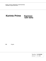
Examples of different tray configurations with indication of their position
The examples shown below correspond to real layouts (indicated on the side); in any case there are many
configurations options with simple and quick change operations (see specific paragraph)
Snakky 6-27R/F Snakky 6-30R/I
Snakky 6-32R/F Snakky 6-33R/E

NECTA SPA TECHNICAL MANUAL “ Snakky “
Manual Snakky 5 / 23
2 - Electrical systems - Connections - Configurations
The machine is designed to operate under a single-phase voltage of 230 V AC (+5-10V)
It is protected with two T 6,3 fuses on both phases.
A safety transformer supplies power to very-low voltage components (24 V), while the cooling unit and the lamps
are powered with the mains voltage.
With regard to the transformer:
The primary winding is protected with a T 800 mA fuse
The secondary winding 25 V is protected with the following fuses:
T 1 A – T 1A
The slide-out compartment is fitted with a safety switch. (10)
The switch is located on the front panel of the power supply unit, and when opening the compartment it
disconnects the power from all parts that can be accessed for normal maintenance and cleaning operations.
The only parts that stay energised are those protected by suitable covers carrying a plate with the warning
"Disconnect power before removing the cover”; to clear the voltage the power the power supply cable must be
disconnected from power outlet.
The power cable can be supplied as standard feature and chosen among
the following types:
HO5 RN – F copper with a 3 x 1.5 mm2 section
HO5 V V – F ,, ,, ,, ,,
HO7 RN – F ,, ,, ,, ,,
Fitted with a fixed SCHUKO plug.
NOTE: For UK there is a specific plug conforming to the standards in
force, which is adopted for that specific market.
In the event of replacement cables of exactly the same
characteristics must be used.
Since the “Snakky” vending machine is approved by an electrical
safety certification institute (IMQ), replacements with non-original
components are not permitted.
Otherwise the electrical safety certificate and the warranty will be
void.
A
CTUATION BOARD AND CONNECTIONS
A neon lamp is located vertically on the
right-hand side inside the cabinet; the
starter is fitted inside the lamp holder.
T
he ballast is located inside the power
supply compartment.
T
he CPU board controls also the 24 V
actuations by means of TRIACs and
Darlin
g
ton switches, while the lamp and
the coolin
g
unit are controlled by a relay
card located inside the power supply
compartment.
Some versions are provided with
monitoring of the selected product fall
into the dispensing compartment by
means of a card with
receiver/transmitter diodes (infrared).
If the barrier is not interrupted it means
that a product is finished or jammed
and the system will further attempt
releasing the product with small
rotations; if also this fails the selection
is disabled and the customer is entitled
to a new selection.
Detail of Power su
pp
l
y
com
p
artment

NECTA SPA TECHNICAL MANUAL “ Snakky “
Manual Snakky 6 / 23
2.1 - ELECTRONIC BOARDS CONNECTIONS
ELECTRICAL AND BOARD CONNECTIONS:
SP push-button card
LCD display
Board
RS232 port
Printer
PC - Programmer
T
ransmitter
photodiode
card
Phototransistor
card
R
ece
iv
e
r
NTC Probe
Cooling unit
control
Cooling unit
control
Lamp
control
Grid: 230 V - 50 Hz
Electric power
supply
Payment
system
connections
Bord SUC
J2: to the
ratiomotors

NECTA SPA TECHNICAL MANUAL “ Snakky “
Manual Snakky 7 / 23
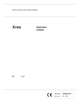
CPU BOARD( SUC)
Ref. N° COMPONENT DESCRIPTION Ref.
N° COMPONENT DESCRIPTION
1 Coin mechanism power supply connector 11 Validator connector
2 Board power supply connector 12 NTC sensor connector
3 GREEN LED 13 LCD display connector
4 YELLOW LED 14 RED LED
5 Connector not used 15 Configuration minidips SW2 (will be
6 Spiral ratiomotor control connector 16 Selection push-button panel connector
7 Input/output connector 17 Expansion board connector for MFB
8 Connector not used 18 Coin mechanism setting minidips
9 Programmer device connector 19 Expansion board connector for BDV / EXE
10 Photodiode barrier connector 20 Validator connector
CPU BOARD LAYOUT
COLOURED LED FUNCTIONS
GREEN LED
blinking during the normal
operation
YELLOW LED
It glows when 5 V DC is present in the
board
RED LED
it glows when the software is reset
(program malfunction)
Minidip functions 1-4 (19)
Coin mechanism setting 2-3
By default set to OFF
Minidips 1-8 (16)
Default configuration setting fixed to
OFF
Both will be eliminated in the near
future, thus since now the
configuration is only via software
setting.
T
he CPU board is housed inside the
payment system compartment, on
the sliding door, and includes all low-
voltage (24 V DC) actuations, it
controls the display, the push-button
card, the photodiode barrier, the
payment system and the NTC probe
that monitors that cooling unit
temperature. The software is written
in a Flash EPROM that, by means of
a special program, can be rewritten
and updated without replacing.
It is powered from the power supply
unit through connection J15 (ref. 2)
T
he photodiode barrier is supplied as
standard feature in some versions,
or as an after-sales kit.

NECTA SPA TECHNICAL MANUAL “ Snakky “
Manual Snakky 8 / 23
TRAY CONNECTION WIRING DIAGRAM
CONNECTO
R
Detail of spiral
control ratiomotor
T
o connector
J2 - SUC
board

NECTA SPA TECHNICAL MANUAL “ Snakky “
Manual Snakky 9 / 23
Description of codes used in the wiring diagrams
Code Description
CF Ratiomotor noise suppressor condenser
CM0-9 Spiral control ratiomotor cam
D Diode
EX Connector for coin mechanism with Executive protocol
FA Grid noise suppressor
FD Transmitter photodiode card
FT Receiver photo-transistor card
IP Sliding panel switch
LCD LCD display card
M1-6 Spiral control ratiomotors
MDB Connector for coin mechanism with MDB protocol
MUR Cooler unit
MVT Electric fan
NTC NTC probe for refrigerated box internal temperature monitoring and control
RS 232 Serial port for PC, printer and programmer connection
RT Neon lamp ballast
SOR Cooling unit control relay card
SP Selection push-button card
ST Neon lamp starter
SUC Central processing unit board
TR Power supply transformer
TX Delayed fuse

NECTA SPA TECHNICAL MANUAL “ Snakky “
Manual Snakky 10 / 23
3 - VENDING AND LOADING SYSTEMS
Availability of spiral pitches and direction
of rotation
Useful pitch:
20, 30, 42, 50, 60, 76 right rotation
30, 42, 50, 60 left rotation
1 - Adjustable tray motor
2 - Minidips controlling the
direction of rotation
3 - Limit micro-switch
4 - Three-pole connector
“Snakky”
is a vending machine belonging to the S & F
range, with product dispensing by means of the rotation
of spirals.
During their rotation the spirals push the product loaded
onto the tray forward.
T
he tray is modular, and by simply movin
g
the partitions
and the motors one, two or three position trays can be
used to dispense any products. Different pitch spirals are
available to be able to load 20 to 76 mm wide products.
In addition the spirals can have right and left pitch, to be
used in the case of two spirals in the same partition.
T
he rear position motor is fitted with a minidip, permittin
g
the inversion of the direction of rotation.
Exam
p
le of tra
y
confi
g
uration with three
p
artitions; a
single one, a double one and a triple one.
T
he tray is held into position by a stop
located on the guides; to slide out the tray
it need to be lifted slightly and then pulled
to the second safety stop. To extract it
completely it needs to be lifted further and
then removed (after disconnecting the
connector located on the right side).

NECTA SPA TECHNICAL MANUAL “ Snakky “
Manual Snakky 11 / 23
4 - WIRING
T
he Snakky is certified by IMQ, therefore the
wiring is complying with the standards and
regulations in accordance with current EC
directives.
T
hey are completely sheathed and double
insulated.
T
he door can be completely removed, as all
cables can be disconnected by means of
connectors all starting from the power supply
unit (FIG. 1).
All main connections for the different function
start from the power supply unit (FIG. 2).
All connections for the vending machine control
start from the CPU board: push-buttons,
payment systems, ratiomotors, heatin
g
elements,
display (FIG. 3).
T
he 230 V 50 Hz
g
rid power supply is
transformed by means of 24 V AC transformer
T
R, then sent to the machine board that rectifies
it to DC and sends it to the users through the
actuations.
A relay card for the 230 V AC actuations is
located in the power supply box, with the
function of controlling the cooling unit.
Wiring for
trays
- Door
wiring
FIG. 1
T
R
Positioning of machine board and relevant
cables on the central sliding partition

NECTA SPA TECHNICAL MANUAL “ Snakky “
Manual Snakky 12 / 23
5 – POWER SUPPLY
T
he power supply unit is totally enclosed in a
galvanised metal box.
It is composed of a safety transformer, supplying
power to all low-voltage functions.
T
he input from the mains is protected with a main
switch and two fuses on both phases.
It is also fitted with a noise suppressor.
T
he CPU boards controls also a relay card for the 230 V
50 Hz actuations.
Lamps, cooling unit and electric fans.
T
he same box houses the ballasts
f
or the neon lamps
and all main fuses, easily accessible from the outside
with the door open.
Safety ke
y
T
ransformer Relay card
Grid noise
suppressor
Connector and fuse
assembly
Lam
p
ballast
Grid input

NECTA SPA TECHNICAL MANUAL “ Snakky “
Manual Snakky 13 / 23
6 – COOLING UNIT AND INTERNAL VENTILATION
The internal temperature control is by means of an NTC type electronic probe fitted with an internal 2267-ohm
resistance (± 7 ohm) at a temperature of 3° C.
As the internal temperature decreases the resistance is increased progressively as indicated in the following table.
This variation allows the software to control the internal temperature with extreme accuracy.
Ref. box int.
temperature
Value in ohm
Allowed tolerance
30° 733 +/-7 ohm
15° 1348 ,,
3° 2267 ,,
0° 2612 ,,
T
he coolin
g
unit is controlled by the relay
card located inside the power supply box
and powered at the grid voltage (SOR
CARD).
When the machine is started, the software
reads the value (in Ohm) from the NTC
probe and, according to the temperature
setting, sends a signal to the relay card
that activates or deactivates the cooling
unit operation.
T
he coolin
g
unit is
v
ery compact and of
the slide-in type; in any case it is designed
to be extracted easily and quickly.
T
o access the coolin
g
unit, the last tray
must be extracted, then the anti-theft
grille and the dispensing compartment
must be removed.
At this point the complete cooling unit can
be extracted.
List of components:
1 - COMPRESSOR
2 - CONDENSER
3 - CONDENSER FAN
4 - EVAPORATOR
5 - EVAPORATOR FAN
6 - PROBE
7 - CABLES
T
he software includes the option of settin
g
time bands for switching on or for safety
temperatures: see details in the
programming manual.
NB. A cooling unit is a real SLIDE-IN type
when it is designed as a complete single
piece unit (e.g. the unit installed on the
StarFood); for the Snakky it is more of a
partial slide-in type, as although it can be
removed completely it is not desi
g
ned as a
single piece functional unit.
Exploded view of cooling unit
condenser
com
p
ressor
Electric fan
p
robe
evaporator
evaporator
fan
cables

NECTA SPA TECHNICAL MANUAL “ Snakky “
Manual Snakky 14 / 23
7 – CABINET
The cabinet is made of pre-varnished sheet-metal,
assembled with rivets and various reinforcements; pre-
formed polystyrene foam insulation panels are placed
between the external pre-varnished sheet-metal part and
the internal refrigerated box part.
The advantage of this solution, compared to the injected
polyurethane foam insulation, is mainly form an
environmental point of view, as in the event of future
scrapping of the machine, the cabinet can be disassembled
completely without any complications (almost impossible in
the case of cabinet injected with foam).
The base is made with varnished and welded sheet-metal,
the feet are adjustable for perfect levelling, and after
removing the lower grille; a trans-pallet can be used to
move the machine.
As optional feature, supports are provided to be placed
under the base, making it possible to position the machine
alongside 1830 mm high vending machines.
As standard feature the Snakky is 1700 mm high.
Perspective view with support and frame, for installation in a bank of 1830 mm high vending
machines.
BASE
SUPPORT

NECTA SPA TECHNICAL MANUAL “ Snakky “
Manual Snakky 15 / 23
8 – DOOR
T
he Snakky is provided with two openin
g
systems: main door and
side sliding compartment.
T
he main door, for loadin
g
products, is of the glass front with
double glazing.
T
he handle for openin
g
is part of the perimeter profile of the
frame, and locking is by means of a single lock located inside the
sliding compartment on the right.
A sliding compartment is located on the side, with the user
interface integrated on its front panel; the CPU board and the
payment system compartment are fitted inside on the central wall.
T
he followin
g
are fitted on the front panel: the main display, the
coin slot and the coin return button, the selection keypad and the
lock, that as well as ensuring a three-point lock it keeps the glass
door closed.
T
he slidin
g
compartment is protected by a safety switch that
disconnects the 230 V AC power, leaving anyway the option of
operating in programming mode by inserting the special key in the
safety switch slot.
Glass door
Slide-out electrical
compartment
Exploded view of the user
interface panel with keypad,
display, coin slot and coin return
compartment.

NECTA SPA TECHNICAL MANUAL “ Snakky “
Manual Snakky 16 / 23
9 – WIRING DIAGRAMS
POWER SUPPLY AND LIGHTING DIAGRAM
1
2
1-2 - power supply to EXE coin
mechanisms
3-4 connector J14 - 24 V DC power
supply card
5-6-7 - in/out connector J3 to board
3 4
5 6 7

NECTA SPA TECHNICAL MANUAL “ Snakky “
Manual Snakky 17 / 23
Wiring diagram of tray ratiomotor controls

NECTA SPA TECHNICAL MANUAL “ Snakky “
Manual Snakky 18 / 23
Wiring diagram of CPU board connection
See page 6 for
connections

NECTA SPA TECHNICAL MANUAL “ Snakky “
Manual Snakky 19 / 23
10 – TROUBLESHOOTING
Problem
(and/or indication on the
display)
Possible cause Solution
The display indicates
the message:
“Compressor”
If the compressor runs for 24 hours
consecutively without the cabinet reaching
the temperature set via the SW, the machine
is locked and the selection disabled.
The following could be the cause:
Lack of gas in the refrigerating circuit.
Failure to the evaporator’s electric fan.
Failure to the condenser’s electric fan or PTC
triggered.
Clogged rear and/or side grille
Failed probe (in this case the message “probe
failure” will be displayed)
Normally two to four hours are required to
reach the operating temperature (according to
the load). A longer time means that there is a
malfunction: check for any small leaks in the
refrigerating gas circuit; if necessary repair the
leak and charge with the correct dose of gas.
Check that the electric fans work correctly.
Check for the correct cooling airflow inside the
refrigerated box. In the case of failure to
components, replace with original parts.
The display indicates
the message
“Coin mechanism”
If the CPU for more than 30 seconds does
not receive communication impulses from an
Executive serial coin mechanism, or 75
seconds from a BDV serial coin mechanism,
or if it receives an impulse for longer than 2
seconds, the machine locks and the
selections are disabled.
Replace the coin mechanism with one that is
certain to work and check the communication.
Check connections.
Check the CPU board, and if necessary replace
with that is certain to work.
Check that the 24 V DC power supply fuse is
intact.
The display indicates
the message
“RAM data”
One or more areas of the RAM contain wrong
data, which could change the operating
default values.
The machine will continue working, but some
parameters could have been changed, with
consequences to the general functioning -
the RAM needs to be initialised as soon as
possible to recover data from the EPROM.
Initialise the CPU again.
After initialising, all data settings will go back to
the default settings; restore the customised
data using the programmer or a PC.
If, in spite of initialising, the malfunction
persists, replace the CPU board with an already
tested one that is certain to work. It the
malfunction persists, replace the cables or
check the suitability of connections.
The machine was designed to comply with the
EMC directive, but if located in an environment
subject to high interference immunity problems
could arise, therefore in the event of such
interference persisting the vending machine
should be moved to a different location.
The display indicates
the message
“Probe”
The temperature control probe in the
refrigerated box is of the NTC type, with the
internal resistance that changes as the
temperature changes.
If the probe is interrupted, the machine locks
after 5 minutes from the failure and the
selections are disabled (THE DISPLAY WILL
INDICATE THE TEMPERATURE – 5 ° C)
If there is a short-circuit in the probe, the
machine locks after 60 minutes and the
selections are disabled (THE DISPLAY WILL
INDICATE THE TEMPERATURE +32° C)
NB: AFTER THE SENSOR FAILURE HAS BEEN
DISPLAYED FOR TWO HOURS, A
COMPRESSOR FAILURE WILL ALSO BE
INDICATED.
Check the internal resistance in the NTC probe
using a digital multimeter: A resistance of 730
ohm corresponds to a temperature of 30° C.
A resistance of 2612 ohm corresponds to a
temperature of 0° C (melting ice).
Replace the probe with an original one; before
installing the new one check that the internal
resistance corresponds to the above
parameters.
Reset the failures by accessing the special
function

NECTA SPA TECHNICAL MANUAL “ Snakky “
Manual Snakky 20 / 23
Problem
(and/or indication on the
display)
Possible cause Solution
The display indicates
the message
“Motor failure n. XY”
At machine start, an automatic test routine
checks the presence of trays and their
number, therefore a motor failure is not
indicated, as they are not activated. When a
selection is made a microswitch is activated,
which must close at the end of the cycle;
should this function not occur the motor
locks or continues running because of an
actuation card failure.
In this case a time-out is triggered to stop
the motor, placing it out of service.
Check that there are no interferences to the
motor rotation.
Check that the motor is efficiently running.
Check that the microswitch is efficiently
working.
Check that in fact there is not a time-out.
If the motor does not pick up at all, check the
electrical connection ensuring that a 24 V DC
reaches the motors.
If all checks are OK replace the card, as the
actuation or the software may be
malfunctioning.
The display indicates
the message
“product finished”
This information can be displayed in the
version fitted with infrared sensors. And it
means that the barrier was not interrupted
during a selection due to two possible
causes: 1) end of product, 2) jammed
product
The software automatically tries to make the
product drop with small movements, and if this
fails the selection is blocked. In this case the
failure must be reset after correcting the
problem.
The software allows a new selection to be
made and the customer does not lose his
credit.
The display indicates a
number of trays not
corresponding to the
real situation
At machine start, an automatic test routine
checks the presence of trays and their
number, therefore if a tray is not indicated it
is because it is not electrically detected.
Check that the cables are correctly connected.
Check that the cables are efficient.
The machine does not
start and the display is
off
The vending machine is protected against
short-circuits with two line fuses (one on
each phase),
with fuses on the secondary winding and on
CPU board power supply (see wiring
diagram).
Check that the fuses are intact and if necessary
replace. First identify the cause of the blown
fuses.
Check the power supply cable.
The transformer’s functioning.
The refrigerated box
does not cool down
and the operating
temperature is not
reached in spite of
being correctly set
The cooling unit is not positioned correctly
and the condenser cooling air does not have
sufficient space for adequate circulation.
The machine is installed in a bank of
machines without a sufficient distance from
the wall.
The amount of refrigerant is not sufficient
(After some time the display indicates the
message “probe failure” or “unit failure”, or
both)
The back of the vending machine can be
positioned right against the wall, but not in a
bank of machines, except when the right side is
kept free.
Check for small leaks using a special instrument
and detecting foam.
Restore the charge after eliminating the leak.
The internal lamps do
not light
Switching on and off of the lamps can be
programmed; therefore check that such
option was not included in the programming.
Probable failure to the starter / ballast
Check the functioning of the neon lamp, starter
and ballast
Check the functioning of the relay card
(SOR) that controls the 230 V AC power supply
Check in the special software program that the
time band setting is correct.
The display indicates
the message:
“programming”
The CPU and payment system compartment
door closure is monitored by a microswitch
that in the event of actuation with the door
open indicates
“Programming”
and does not allow the correct function if the
warning is with the door closed. Check the
microswitch.
Check that microswitches are activated
correctly, check that cables are not damaged or
disconnected.
Replace the microswitches and/or the cables
/