Greenheck 460945 ERT Operating instructions
- Category
- Split-system air conditioners
- Type
- Operating instructions

®
Document 460945
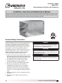
Model ERT
Energy Recovery Ventilator with Tempering
Installation, Operation and Maintenance Manual
Please read and save these instructions for future reference. Read carefully before attempting to assemble, install,
operate or maintain the product described. Protect yourself and others by observing all safety information. Failure
to comply with instructions could result in personal injury and/or property damage!
Energy Recovery Ventilator with Tempering 1
®
Only qualified personnel should install this system.
Personnel should have a clear understanding of these
instructions and should be aware of general safety
precautions. Improper installation can result in electric
shock, possible injury due to coming in contact with
moving parts, as well as other potential hazards,
including environmental. Other considerations may be
required if high winds or seismic activity are present.
If more information is needed, contact a licensed
professional engineer before moving forward.
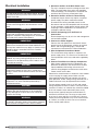
1. Follow all local electrical and safety codes, as well as
the National Electrical Code (NEC), the National Fire
Protection Agency (NFPA), where applicable. Follow
the Canadian Electrical Code (CE) in Canada.
2. All moving parts must be free to rotate without
striking or rubbing any stationary objects.
3. Unit must be securely and adequately grounded.
4. Do not spin fan wheel faster than maximum
cataloged fan RPM. Adjustments to fan speed
significantly affect motor load. If the fan RPM is
changed, the motor current should be checked to
make sure it is not exceeding the motor nameplate
amps.
5. Verify that the power source is compatible with the
equipment.
6. Never open access doors to the unit while it is
running.
General Safety Information
DANGER
Always disconnect power before working on or near
this equipment. Lock and tag the disconnect switch or
breaker to prevent accidental power up.
CAUTION
When servicing the unit, the internal components may
be hot enough to cause pain or injury. Allow time for
cooling before servicing.
WARNING
The roof lining contains high voltage wiring. To prevent
electrocution, do not puncture the interior or exterior
panels of the roof.

2
Energy Recovery Ventilator with Tempering
Table of Contents
General Safety Information ...................1
Receiving, Handling and Storage ..............3
Product Overview ...........................4
Optional Subassemblies ......................4
Installation
Unit Dimensions and Weights ..................5
Curb Outside Dimensions, Recommended
Roof Openings and Curb Weights .............5
Service Clearances and Access Locations ........6
Handling ...................................6
Lifting . . . . . . . . . . . . . . . . . . . . . . . . . . . . . . . . . . . . .7
Roof Curb Mounting .........................7
Optional Piping Vestibule ......................8
Rail Mounting/Layout .........................8
Duct Connections ...........................9
Electrical Installation
Procedure .................................10
Field-Provided Disconnect ....................11
Discharge Air Temperature Sensor .............11
Typical Control Center Components ............11
Optional Accessory Wiring Schematics ..........12
Piping Installation
Optional Coil Piping .........................13
Condensate Drain Trap ......................13
Unit Overview
Basic Unit .................................14
Optional Component Overview
Economizer ...............................14
Frost Control ..............................15
Variable Frequency Drive .....................15
CO
2
Sensor ...............................15
Rotation Sensor ............................15
Dirty Filter Sensor ..........................15
Microprocessor Control ......................15
Unoccupied Recirculation Damper .............16
Service Outlet ..............................16
Vapor Tight Lights ..........................16
Smoke Detector ............................16
Exhaust Fan Only Power .....................16
Airflow Monitor .............................16
Start-Up
Warnings .................................17
Special Tools Required ......................17
Start-Up Procedure .........................17
Voltage Imbalance ..........................17
Pre-Start-Up Checklist .......................18
Start-Up Checklist ..........................18
Optional Accessories Checklist ................19
Start-Up Components
Energy Wheel ..............................20
Fans . . . . . . . . . . . . . . . . . . . . . . . . . . . . . . . . . 20-21
Vibration ..................................21
Optional Start-Up Components
Dirty Filter Switch ...........................22
Economizer ............................22-23
Frost Control ..............................23
Airflow Monitor
.............................24
Variable Frequency Drives ................25-26
Routine Maintenance
Maintenance Frequency ......................27
Maintenance Procedures
Lubrication ..............................28
Dampers ................................28
Fan Belts ...............................28
Fan Motors ..............................28
Fan Wheel & Fasteners ....................28
Bearings ................................28
Internal Filter ............................29
External Filter ............................29
Coils ...................................29
Door Seals ..............................29
Energy Wheel ............................30
Troubleshooting
Unit . . . . . . . . . . . . . . . . . . . . . . . . . . . . . . . . . . . .31
Energy Wheel ..............................32
Controller Alarms ...........................33
Rotation Sensor ............................33
Economizer ...............................33
Maintenance Log ........................34-35
Our Commitment ....................Backcover

3
Energy Recovery Ventilator with Tempering
Receiving
This product may have been subject to road salt during
transit. If so, immediately wash off all visible white
reside from all exterior surfaces. Upon receiving the
product, check to ensure all line items are accounted
for by referencing the delivery receipt or packing list.
Inspect each crate or carton for shipping damage before
accepting delivery. Alert the carrier if any damage is
detected, do not refuse shipment. The customer shall
make notation of damage (or shortage of items) on the
delivery receipt and all copies of the bill of lading should
be countersigned by the delivering carrier. If damaged,
immediately contact your manufacturer’s representative.
Any physical damage to the unit after acceptance is not
the responsibility of the manufacturer.
Handling
Units are to be rigged and moved by the lifting brackets
provided or by the skid when a forklift is used. Location
of brackets varies by model and size. Handle in such
a manner as to keep from scratching or chipping the
coating. Damaged finish may reduce ability of unit to
resist corrosion.
Unpacking
Verify that all required parts and the correct quantity
of each item have been received. If any items are
missing, report shortages to your local representative to
arrange for obtaining missing parts. Sometimes it is not
possible that all items for the unit be shipped together
due to availability of transportation and truck space.
Confirmation of shipment(s) must be limited to only
items on the bill of lading.
Storage
Units are protected against damage during shipment. If
the unit cannot be installed and operated immediately,
precautions need to be taken to prevent deterioration of
the unit during storage. The user assumes responsibility
of the unit and accessories while in storage. The
manufacturer will not be responsible for damage during
storage. These suggestions are provided solely as a
convenience to the user.
The ideal environment for the storage of units and
accessories is indoors, above grade, in a low humidity
atmosphere which is sealed to prevent the entry of
blowing dust, rain, or snow. Units designed for outdoor
applications may be stored outdoors. All accessories
must be stored indoors in a clean, dry atmosphere.
Indoor
Maintain temperatures evenly to prevent condensation.
Remove any accumulations of dirt, water, ice, or snow
and wipe dry before moving to indoor storage. To
avoid condensation, allow cold parts to reach room
temperature. Leave coverings loose to permit air
circulation and to allow for periodic inspection.
The unit should be stored at least 3½ in. (89 mm) off
the floor. Clearance should be provided to permit air
circulation and space for inspection.
Outdoor
The unit should be placed on a level surface to prevent
water from leaking into the unit. The unit should be
elevated so that it is above water and snow levels.
Ensure sufficient support to prevent unit from settling
into soft ground. Locate parts far enough apart to
permit air circulation, sunlight, and space for periodic
inspection. To minimize water accumulation, place all
unit parts on blocking supports so that rain water will
run off.
Do not cover parts with plastic film or tarps as these
cause condensation of moisture from the air passing
through heating and cooling cycles.
Inspection and Maintenance
While in storage, inspect units once per month. Keep a
record of inspection and maintenance performed.
If moisture or dirt accumulations are found on parts,
the source should be located and eliminated. At each
inspection, rotate the fan wheel by hand ten to fifteen
revolutions to distribute lubricant on motor. If paint
deterioration begins, consideration should be given to
touch-up or repainting. Units with special coatings may
require special techniques for touch-up or repair.
Machined parts coated with rust preventive should be
restored to good condition promptly if signs of rust
occur. Immediately remove the original rust preventive
coating with petroleum solvent and clean with lint-free
cloths. Polish any remaining rust from surface with
crocus cloth or fine emery paper and oil. Do not destroy
the continuity of the surfaces. Wipe thoroughly clean
with Tectyl
®
506 (Ashland Inc.) or the equivalent. For
hard to reach internal surfaces or for occasional use,
consider using Tectyl
®
511M Rust Preventive, WD-40®
or the equivalent.
Removing from Storage
As units are removed from storage to be installed
in their final location, they should be protected and
maintained in a similar fashion until the equipment goes
into operation.
Prior to installing the unit and system components,
inspect the unit assembly to make sure it is in working
order.
1. Check all fasteners, set screws on the fan, wheel,
bearings, drive, motor base, and accessories for
tightness.
2. Rotate the fan wheel(s) by hand and assure no parts
are rubbing.

4
Energy Recovery Ventilator with Tempering
Split DX
The unit is equipped with an evaporator coil that
will be connected to a separate condensing unit
(provided by others). Depending on controlling options,
the condensing unit will be controlled by others or
an integral unit microprocessor controller. Piping
components such as thermostatic expansion valve, filter
drier, sight glass, etc., shall be field-provided.
Electric Post-Heaters
The optional post-heater is used as a heat source for
the building and is integrated into the supply airstream.
A temperature sensor (with a field-adjustable set point)
is mounted in the supply airstream after the post-heater
to turn the post-heater on. A SCR heater allows for
an infinite amount of modulating control of the heat to
provide an accurate discharge temperature during the
call for heat.
As standard, the post-heater control panel is not single
point wired to the unit control center. Separate power
must be supplied to the post-heater disconnect (located
in unit control center). Electric heaters are available in
208, 230, 460, or 575 VAC (refer to heater nameplate for
voltage).
Outdoor Air Weatherhood
Outdoor air weatherhood will be factory-mounted.
Exhaust Air Weatherhood
The exhaust weatherhood is shipped separately as a
kit with its own instructions. Backdraft dampers are
always included as an integral part of the exhaust hood
assemblies.
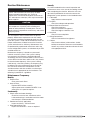
Product Overview
The model ERT combines the benefits of energy
recovery, wrap-around heat pipe, cooling coil and
optional heating sources. Heating sources include
electric, hot water. Cooling sources include split direct
expansion and chilled water. This product is specifically
designed to process 100% outdoor air to desired
supply conditions. Three housing sizes provide airflow
capacities from 2,000 to 10,000 cfm with external static
pressures up to 1.75 in. wg.
Optional Subassemblies
Dampers
There are four locations where dampers can be
installed. Low leakage or insulated low leakage
motorized dampers can be added in the outdoor
airstream and/or return airstream. An unoccupied
recirculating air damper is also available. A backdraft
damper is standard in the exhaust hood.
Filters
There is the option of either two-inch thick MERV 8
or MERV 8 and 13 pre-filters in the outdoor airstream
and MERV 8 filters in the exhaust airstream. There are
also permanent washable aluminum mesh filters in the
optional weatherhood.
Hot Water / Chilled Water Coils
Water coils can be used for a single purpose such
as heating or cooling, or their function can be
alternated between heating and cooling by changing
the temperature of the water flowing through the coil.
Depending on the application, it may be necessary to
use a glycol mixture to prevent the liquid from freezing.
The water coils are engineered to operate at pressures
up to 250 PSIG and temperatures up to 300°F, but
ancillary equipment such as valves and pumps will often
dictate lower operating temperatures. All water coils
are pressure tested at the factory with 450 PSIG of dry
nitrogen.
OUTDOOR AIR
WEATHERHOOD
EXHAUST AIR
WEATHERHOOD
SUPPLY FILTERS
WHEEL CASSETTE
EXHAUST FILTERS
CONTROL
CENTER
HEATPIPE
HEATPIPE
COOLING
COIL
HEATING
COIL
RETURN AIR
INTAKE DAMPER
DAMPER
BACKDRAFT
EXHAUST DAMPER
PERMANENT
ALUMINUM
MESH FILTERS
MOTORIZED OUTDOOR
AIR DAMPER
TWO-INCH THICK MERV 8 OR MERV
8 AND 13 PLEATED FILTERS
MOTORIZED RECIRCULATING
AIR DAMPER
TWO-INCH THICK MERV 8
PLEATED FILTERS
MOTORIZED RETURN
AIR DAMPER

5
Energy Recovery Ventilator with Tempering
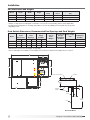
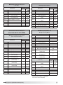
Unit Dimensions and Weights
Installation
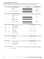
Model Length Width Height
Exhaust
Hood
Outdoor Air
Hood
Approximate Weight
(lbs)
ERT-45 119.3 64.4 70.2 20.7 21.7 3100
ERT-55 133.5 75.2 71 23.6 21.7 3625
ERT-90 151.5 94.5 89 25.5 26.7 5800
All dimensions are in inches. Unit weights assume rooftop configuration with weatherhood, filters, outdoor air
damper, cooling options, including but not limited to a six row dx coil, and heating options (where applicable).
The approximate weight (lbs) is assuming all possible accessories are added per housing and may vary by 10%
depending on unit.
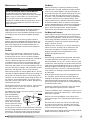
Curb Outside Dimensions, Recommended Roof Openings and Curb Weights
RETURN AIR
INLET
SUPPLY AIR
DISCHARGE
A
B
26.1
C
D
L
W
Curb
Height
1/2 inch
1.63
inches
1.9 inches
Unit Base
Curb Duct
Adaptor
1 inch
Curb
1-inch Foam Insulation
Roof Curb Detail
Model
Outside
Curb
Dimensions
Recommended
Roof
Openings
Optional
Piping
Vestibule
12 inch
Curb
Weight
12 inch Curb
Weight
with Piping
Vestibule
Curb weight
only
Curb Weight
with Piping
Vestibule
Length Width A B C D
Adder per inch
ERT-45 114.9 60 31.8 54.8 48.1 32.8 195 228 +9.5 +11.4
ERT-55 129.1 70.8 38.3 63.5 54.8 32.8 228 260 +10.9 +12.7
ERT-90 147.1 90.1 39.1 79.4 64.1 32.8 291 323 +13.1 +14.9
All dimensions are in inches. All weights are in pounds.
Various curb heights are available; use the adder per inch column to determine the weights above 12 inches.

6
Energy Recovery Ventilator with Tempering
Service Clearances / Access Panel
Units require minimum clearances for access on all sides for routine maintenance. Filter replacement, drain pan
inspection and cleaning, energy wheel cassette inspection, fan bearing lubrication and belt adjustment are examples
of routine maintenance that must be performed. Blower and motor assemblies, energy recovery wheel cassette, coil
and filter sections are always provided with a service door or panel for proper component access.
EXHAUST FILTERS
SUPPLY FILTERS
EXHAUST
AIR HOOD
WHEEL CASSETTE
OUTDOOR
AIR HOOD
ELECTRICAL BOX
B
*CASSETTE REMOVAL
ACCESS DOOR
ACCESS DOOR
ACCESS DOOR
ACCESS DOOR
ACCESS DOORS
0"
A
ACCESS DOORS
COOLING COIL
HEATING COIL
ACCESS PANEL
PIPING VESTIBULE
(OPTIONAL)
48"36"
CLEARANCE
WITH
VESTIBULE
CLEARANCE
WITHOUT
VESTIBULE
HEAT PIPE
*CASSETTE REMOVAL ONLY AVAILABLE
ON HOUSING SIZE 45
Model A (in.) B (in.)
ERT-45 60 42
ERT-55 36 42
ERT-90 36 52
Handling
While this unit was constructed with quality and dependability in mind, damage still may occur during handling of the
unit for installation.
The system design and installation should follow accepted industry practice, such as described in the ASHRAE
Handbook. Adequate space should be left around the unit for piping coils and drains, filter replacement, and
maintenance. Sufficient space should be provided on the side of the unit for routine service and component removal
should that become necessary.

7
Energy Recovery Ventilator with Tempering
Lifting
WARNING
All factory-provided lifting lugs must be used when
lifting the units. Failure to comply with this safety
precaution could result in property damage, serious
injury, or death.
1. Before lifting, be sure that all shipping material has
been removed from unit.
2. To assist in determining rigging requirements,
weights are provided in the Installation, Unit
Dimensions and Weights section of this manual.
3. Unit must be lifted by all lifting lugs provided on
base structure.
4. Rigger to use suitable mating hardware to attach to
unit lifting lugs.
5. Spreader bar(s) must span the unit to prevent
damage to the cabinet by the lift cables.
6. Always test-lift the unit to check for proper balance
and rigging before hoisting to desired location.
7. Never lift units by weatherhoods.
8. Never lift units in windy conditions.
9. Preparation of curb and roof openings should be
completed prior to lifting unit to the roof.
10. Check to be sure that gasketing (supplied by
others) has been applied to the curb prior to lifting
the unit and setting on curb.
11. Do not use fork lifts for handling unit.
NOTE
Install and caulk covers over lift points after unit is
installed to ensure weatherization.
Roof Curb Mounting
Rooftop units require curbs to be mounted first. The
duct connections must be located so they will be clear
of structural members of the building.
Position the unit roof opening such that the supply
discharge and exhaust inlet of the unit will line up with
the corresponding ductwork. Be sure to allow for the
recommended service clearances when positioning
opening.
Do not face the outdoor air intake of the unit into
prevailing wind and keep the intake away from any other
exhaust fans. Likewise, position the exhaust discharge
opening away from outdoor air intakes of any other
equipment.
1. Factory-Supplied Roof Curbs Roof curbs are
Model GKD, which are shipped in a knockdown kit
(includes duct adapter) and require field assembly
(by others). Assembly instructions are included with
the curb.
2. Install Curb Locate curb over
roof opening and fasten
in place. Reference
Installation, Curb
Outside Dimensions,
Recommended
Roof Openings
and Weights in this
manual. Check
that the diagonal
dimensions are within
±1/8 inch of each
other and adjust as
necessary. For proper
coil drainage and
unit operation, it is
important that the
installation be level.
Shim as required to
level.
3. Install Ductwork Installation of all ducts should
be done in accordance with SMACNA and AMCA
guidelines. Duct adapter provided to support ducts
prior to setting the unit.
4. Set the Unit Lift unit to a point directly above the
curb and duct openings. Guide unit while lowering
to align with duct openings. Roof curbs fit inside the
unit base. Make sure the unit is properly seated on
the curb and is level. Gasketing (by others) needs
to be installed to curb creating a seal between the
ductwork and the base of the unit.

8
Energy Recovery Ventilator with Tempering
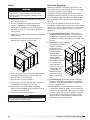
Rail Mounting
Unit Size A B
ERT-45 7.0 41.9
ERT-55 5.5 53.0
ERT-90 6.0 59.0
All dimensions are in inches.
Rail Mounting / Layout
1. Rails designed to handle the weight of the unit
should be positioned as shown on the diagram (rails
by others).
2. Make sure that rail positioning does not interfere with
the supply air discharge opening or the exhaust air
intake opening on the unit. Avoid area dimensioned
“B” below.
3. Rails should run the width of the unit and extend
beyond the unit a minimum of 12 inches on each
side.
4. Set unit on rails.
BA
Optional Piping Vestibule
Insulated enclosure that is mounted externally to the
unit in order to protect the water supply and return
piping. Not available in models with water-source heat
pump or evaporative cooling.
EXHAUST BLOWER
ACCESS DOOR
OUTDOOR AIR
WEATHERHOOD
CASSETTE/FILTER
ACCESS DOOR
PIPING VESTIBULE
DRAIN PAN
CONNECTION
SUPPLY BLOWER
ACCESS DOOR
Cooling Coil (with or without heating)
Unit Size Weight
ERT-45 235
ERT-55 235
ERT-90 280
All weights are in pounds.

9
Energy Recovery Ventilator with Tempering
R
o
t
a
t
i
o
n
Length of Straight Duct
GOOD
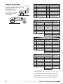
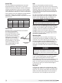
Ductwork Connections
Examples of poor and good fan-to-duct connections
are shown. Airflow out of the fan should
be directed straight or curve the
same direction as the
fan wheel rotates. Poor
duct installation will result
in low airflow and other
system effects.
R
o
t
a
t
i
o
n
POOR
ERT-45
Recommended
Duct Size
Intake Duct Size Discharge 12-12 Blower
OIE 28 x 36 SDE 20 x 20
OIT 34 x 24 SDS 20 x 20
RIE 24 x 40 SDT 20 x 20
RIS 26 x 32 SDT/IG 28 x 28
RIB 20 x 48 SDB 16 x 18
RIT 28 x 30 EDE 20 x 20
EDT 20 x 20
EDS 20 x 20
ERT-55
Recommended
Duct Size
Intake Duct Size Discharge 15-15 Blower
OIE 32 x 52 SDE 28 x 28
OIT 40 x 28 SDS 28 x 28
RIE 30 x 40 SDT 28 x 28
RIS 30 x 38 SDT/IG 38 x 30
RIB 20 x 54 SDB 18 x 20
RIT 30 x 40 EDE 28 x 28
EDT 28 x 28
EDS 28 x 28
ERT-90
Recommended
Duct Size
Intake Duct Size Discharge 18-18 Blower
OIE 34 x 64 SDE 32 x 32
OIT 34 x 50 SDS 32 x 32
RIE 32 x 60 SDT 32 x 32
RIS 40 x 40 SDT/IG 34 x 33
RIB 22 x 74 SDB 20 x 24
RIT 40 x 40 EDE 32 x 32
EDT 32 x 32
EDS 32 x 32
All dimensions shown in inches.
• Recommended duct sizes are based on velocities across the cfm
range of each model at approximately 800 feet per minute (FPM) at
minimum airflow and up to 1600 fpm at maximum airflow.
• Recommended duct sizes are only intended to be a guide and
may not satisfy the requirements of the project. Refer to plans for
appropriate job specific duct size and/or velocity limitations.
Inlet/Outlet Descriptions
Code Description Code Description
OIE Outdoor Air Intake End SDT Supply Discharge Top
OIT Outdoor Air Intake Top SDT/IG Supply Discharge Top w/IG
RIE Return Air Intake End SDS Supply Discharge Side
RIS Return Air Intake Side SDB Supply Discharge Bottom
RIB Return Air Intake Bottom EDE Exhaust Discharge End
RIT Return Air Intake Top EDT Exhaust Discharge Top
SDE Supply Discharge End EDS Exhaust Discharge Side

10
Energy Recovery Ventilator with Tempering
WARNING
The roof lining contains high voltage wiring. To prevent
electrocution, do not puncture the interior or exterior
panels of the roof.
WARNING
To prevent injury or death due to electrocution or
contact with moving parts, lock disconnect switch
open.
IMPORTANT
Before connecting power to the unit, read and
understand the following instructions and wiring
diagrams. Complete wiring diagrams are attached on
the inside of the control center door(s).
IMPORTANT
All wiring should be done in accordance with the latest
edition of the National Electrical Code ANSI/NFPA70
and any local codes that may apply. In Canada, wiring
should be done in accordance with the Canadian
Electrical Code.
IMPORTANT
The equipment must be properly grounded and
bonded. Any wiring running through the unit in the
airstream must be protected by metal conduit, metal
clad cable or raceways.
CAUTION
If replacement wire is required, it must have a
temperature rating of at least 105°C, except for an
energy cut-off or sensor lead wire which must be rated
to 150°C.
DANGER
High voltage electrical input is needed for this
equipment. This work should be performed by a
qualified electrician.
CAUTION
Any wiring deviations may result in personal injury or
property damage. Manufacturer is not responsible
for any damage to, or failure of the unit caused by
incorrect final wiring.
WARNING
If unit is equipped with a microprocessor, terminals Y1,
Y2 and W1 cannot be wired to a thermostat. Wiring to
these terminals will bypass unit’s internal safeties.
Electrical Installation
1. Determine the Size of the Main Power Lines
The unit’s nameplate states the voltage and the unit’s
MCA. The main power lines to the unit should be
sized accordingly. The nameplate is located on the
outside of the unit on the control panel side.
2. Determine the Size of Electric Heater Wiring
An optional electric heater may require a separate
power supply. The power connection should
be made to the factory-provided electric heater
disconnect and must be compatible with the ratings
on the nameplate, supply power voltage, phase and
amperage. Consult ANSI/NFPA 70 and CSA C22.1
for proper conductor sizing.
3. Provide the Opening(s) for the Electrical
Connections
Electrical openings vary by unit size and arrangement
and are field-supplied.
4. Connect the Power Supplies
Connect the main power lines and electric heater
power lines to the disconnect switches or terminal
blocks and main grounding lug(s). Torque field
connections to manufacturer’s recommendations.
5. Wire the Optional Convenience Outlet
The convenience outlet requires a separate 115V
power supply circuit. The circuit must include short
circuit protection which may need to be supplied by
others.
6. Connect Field-Wired Low Voltage Components
Most factory-supplied electrical components are
prewired. To determine what electrical accessories
require additional field-wiring, refer to the unit-
specific wiring diagram located on the inside of the
control center access door.
Control wires should not be run inside the same conduit
as that carrying the supply power. Make sure that
field-supplied conduit does not interfere with access
panel operation. All low voltage wiring should be run in
conduit wherever it may be exposed to the weather.
The low voltage control circuit is 24 VAC and control
wiring should not exceed 0.75 ohms. If wire resistance
exceeds 0.75 ohms, an isolation relay should be added
to the unit control center and wired in place of the
remote switch (typically between terminal blocks R
and G on the terminal strip. The relay must be rated
for at least 5 amps and have a 24 VAC coil. Failure to
comply with these guidelines may cause motor starters
to “chatter” or not pull in which can cause contactor
failures and/or motor failures.

11
Energy Recovery Ventilator with Tempering
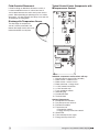
Typical Control Center Components with
Microprocessor Control
Individual components and locations will vary.
1. Main disconnect (non-fusible, lockable)
2. Motor starter - outdoor air fan
3. Motor starter - exhaust air fan
4. Motor contactor - energy wheel
5. 24 VAC control transformer
6. 24 VAC terminal strip
7. Fuses for blower motors
8. Grounding lug
9. Distribution block
10. Terminal block
Optional Components
11. Microprocessor controller
12. Dirty filter pressure switches
13. Economizer module
14. Thermostats for
• Economizer module
• Energy recovery wheel frost control
15. GreenTrol®
16. Frost control pressure switch
17. Energy recovery wheel VFD
Field-Provided Disconnect
If field-installing an additional disconnect switch, it
is recommended that there is at least four feet of
service room between the switch and system access
panels. When providing or replacing fuses in a fusible
disconnect, use dual element time delay fuses and size
according to the rating plate.
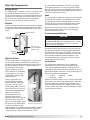
Discharge Air Temperature Sensor
The discharge air temperature
sensor is factory-mounted in the
blower discharge section of the unit
behind the blower cut off plate.
8
1
7
9
5
4
17
2
3
10
11 14
13
16
15
12
6

12
Energy Recovery Ventilator with Tempering
W1
12
7
6
Y2
Y1
G
C
R
TERMINAL BLOCKS IN
UNIT CONTROL CENTER
TIMER
BLACK BLUE
RED
(CAPPED)
7-Day Timer
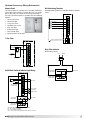
Optional Accessory Wiring Schematics
Remote Panel
The remote panel is available with a number of different
alarm lights and switches to control the unit. The remote
panel ships loose and requires mounting and wiring in
the field. The remote panel is available with the following
options:
• Unit on/off switch
• Unit on/off light
• 7-day time clock
• Hand/off/auto switch
• Dirty filter light
• Economizer light
• Frost control light
• Wheel rotation sensor light
NC
C
NC
C
NO
NO
DIRTY FILTER
EXHAUST DIRTY
FILTER SWITCH
SUPPLY DIRTY
FILTER SWITCH
HOT COMMON
Dirty Filter Indicator
(Powered by others)
A
W1
12
7
6
Y2
Y1
G
C
R
UNIT ON/OFF
COOL STAGE 1 / ECONOMIZER
COOL STAGE 2
UNOCCUPIED RECIRCULATION
S1
S6
S7
S4
S5
HEAT
TERMINAL BLOCKS IN
UNIT CONTROL CENTER
Unit Interfacing Terminals
Heating/Cooling Switches and Night Setback Switch/
Timer
W1
12
7
6
Y2
Y1
G
C
R
NC
C
NC
C
NO
NO
UNIT ON/OFF
FROST CONTROL
ECONOMIZER
WHEEL ROTATION
DIRTY FILTER
ON
OFF
AUTO
*
* -- BMS, TIMECLOCK,
TERMINAL BLOCKS IN
UNIT CONTROL CENTER
ON/OFF/AUTO SWITCH ALLOWS THREE MODES OF OPERATION
"ON" - UNIT IS TURNED ON MANUALLY
"OFF" - UNIT IS TURNED OFF MANUALLY
"AUTO" - UNIT IS CONTROLLED VIA SCHEDULER OF BMS, TIMECLOCK, TSAT, ETC.
TSTAT, RTU, ETC.
EXHAUST DIRTY
FILTER SWITCH
SUPPLY DIRTY
FILTER SWITCH
On/Off/Auto Switch & Indictor Light Wiring

13
Energy Recovery Ventilator with Tempering
Piping Installation
Optional Coil Piping
Factory-installed cooling and heating components are
mounted in the coil section of the unit. The coil section
is downstream of the energy wheel on the supply air
side of the unit. Note the coil connection locations on
the picture. Coil connections are located external to the
unit as shown.
Note: DX coil liquid connection is internal to units.
Water Coils
1. Piping should be in accordance with accepted
industry standards. Pipework should be supported
independently of the coils. When installing couplings,
do not apply undue stress to the connection
extending through the unit. Use a backup pipe
wrench to avoid breaking the weld between coil
connection and header.
2. Connect the water supply to the bottom connection
on the air leaving side and the water return to the
top connection on the air entering side. Connecting
the supply and/or return in any other manner will
result in very poor performance. Be sure to replace
factory-installed grommets around coil connections
if removed for piping. Failure to replace grommets
will result in water leakage into the unit and altered
performance.
3. Water coils are not normally recommended for
use with entering air temperatures below 40°F. No
control system can be depended on to be 100% safe
against freeze-up with water coils. Glycol solutions
or brines are the only safe media for operation of
water coils with low entering air conditions. If glycol
or brine solutions are not used, coils must be drained
when freezing conditions are expected. If required,
vent and drain connections must be field-
piped, external to the unit.
4. Pipe sizes for the system must be selected on
the basis of the head (pressure) available from the
circulation pump. The velocity should not exceed
6 feet per second and the friction loss should be
approximately 3 feet of water column per 100 feet
of pipe.
5. For chilled water coils, the condensate drain
pipe should be sized adequately to ensure the
condensate drains properly. Refer to Condensate
Drain Trap section.
Direct Expansion (DX) Coils (Split DX)
1. Piping should be in accordance with accepted
industry standards. Pipework should be supported
independently of the coils. Undue stress should not
be applied at the connection to coil headers.
2. The condensate drain pipe should be sized
adequately to ensure the condensate drains properly.
Refer to Condensate Drain Trap section.
3. When connecting suction and liquid connections
make sure the coil is free from all foreign material.
Make sure all joints are tight and free of leakage. Be
sure to replace factory-installed grommets around
coil connections if removed for piping.
4. Manufacturer does not supply compressor or
condensing units with standard models. For further
instruction on DX coil installation and operation
contact your compressor and/or condenser
manufacturer.
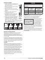
Condensate Drain Trap
This unit is equipped with a stainless steel condensate
pan with a 1-inch MPT stainless steel drain connection.
It is important that the drain connection be fitted with a
P trap to ensure proper drainage of condensate while
maintaining internal static pressures.
A P trap assembly (kit) is supplied with each unit and
is to be assembled and installed as local conditions
require and according to the
assembly instructions provided
with the P trap. If local and area
codes permit, the condensate
may be drained back onto the
roof, but a drip pad should be
provided beneath the outlet. If
local and area codes require a
permanent drain line, it should
be fabricated and installed in
accordance with Best Practices and all codes.
In some climates, it will be necessary to provide freeze
protection for the P trap and drain line. The P trap
should be kept filled with water or glycol solution at
all times and it should be protected from freezing to
protect the P trap from damage. If severe weather
conditions occur, it may be necessary to fabricate a P
trap and drain line of metal and install a heat tape to
prevent freezing.
Water coil
connections
DX coil
liquid
connection
access
door

14
Energy Recovery Ventilator with Tempering
Unit Overview
Basic Unit
The unit is pre-wired such that when a call for outside
air is made (via field-supplied 24 VAC control signal
wired to unit control center), the supply fan, exhaust fan,
and energy wheel are energized and optional motorized
dampers open.
The unit can be supplied with or without heating and
cooling coils. For units with coils, controls can be
supplied by manufacturer or by the controls contractor.
If supplied by the controls contractor, they would
provide, mount, and wire any temperature controllers
and temperature or relative humidity sensors required
for the unit to discharge air at the desired conditions.
However, temperature, pressure, and current sensors
can be provided by manufacturer for purposes of
monitoring via the BMS.
Summer Operation
Outdoor air is preconditioned (temperature and moisture
levels are decreased) by the transfer of energy from the
cooler, drier exhaust air via the energy recovery wheel.
Units supplied with cooling coils can further cool the
air coming off the wheel and strip out moisture to levels
at or below room design. A heating coil downstream of
the cooling coil can reheat the air to a more comfortable
discharge temperature to the space.
Winter Operation
Outdoor air is preconditioned (temperature and moisture
levels are increased) by the transfer of energy from the
warmer, more humid exhaust air via the energy recovery
wheel. Units supplied with heating coils can further heat
the air coming off the wheel to levels at or above room
design.
Exhaust Air
Outdoor Air
95°F
117 grains/lb.
Supply Air
79°F
75 grains/lb.
Return Air
75°F
50% RH
Exhaust Air
Outdoor Air
10°F
5 grains/lb.
Supply Air
60°F
39 grains/lb.
Return Air
72°F
40% RH
Optional Component Overview
Economizer
The energy wheel operation can be altered to take
advantage of economizer operation (free cooling).
Two modes are available:
1. Stopping the wheel
2. Modulating the wheel
Stopping the wheel: A field-supplied call for cool (Y1)
is required. De-energizing the wheel is accomplished in
one of three ways:
1. The outdoor air temperature is less than the
outdoor dry bulb set point (DRYBLB SET)
2. The outdoor air temperature is less than the return
air temperature
3. The outdoor air enthalpy is within the preset
enthalpy curve
A low temperature lock out (LOW T LOCK) is also set
to deactivate mechanical cooling when it exceeds
the outdoor air temperature (factory default 32°F).
Effectively, the two sensors create a deadband where
the energy recovery wheel will not operate and free
cooling from the outside can be brought into the
building unconditioned.
Modulating the wheel (factory): A variable frequency
drive is fully programmed at the factory. A “call for cool”
must be field-wired to the unit. (Terminals provided
in unit. Refer to wiring diagram in unit control center).
to allow for initiation of economizer mode. The unit
recognizes economizer conditions based on one of the
previously mention sensors and set points. The unit will
then modulate the wheel speed to maintain the mixed
air temperature set point (MAT SET).
Modulating the wheel (by others): A variable
frequency drive is fully programmed at the factory.
A field-supplied 0-10 VDC signal will be required for
operation of the energy wheel. The field will be required
to have full control of the energy wheel speed at all
times. If no 0-10 VDC signal is provided, the energy
wheel will run at the factory default of 3 Hz and no
energy transfer will be captured.

15
Energy Recovery Ventilator with Tempering
Frost Control
Extremely cold outdoor air temperatures can cause
moisture condensation and frosting on the energy
recovery wheel. Frost control is an optional feature that
will prevent/control wheel frosting. Three options are
available:
1. Timed exhaust frost control
2. Electric preheat frost control
3. Modulating wheel frost control
All of these options are provided with a thermodisc
mounted in the outdoor air intake compartment and a
pressure sensor to monitor pressure drop across the
energy wheel.
An outdoor air temperature of below 5°F and an
increase in pressure drop would indicate that frost is
occurring. Both the pressure sensor and the outdoor air
thermodisc must trigger in order to initiate frost control.
The two sensors together ensure that frost control is
only initiated during a real frost condition.
Timed exhaust frost control includes a timer in
addition to the thermodisc and wheel pressure sensor.
When timed exhaust frost control is initiated, the timer
will turn the supply blower off. Timed exhaust, using
default timer setting, will shut down the supply fan for
5 minutes every 30 minutes to allow exhaust to defrost
energy wheel. Use the test procedure in the Optional
Start-Up Accessories section for troubleshooting.
Electric preheat frost control includes an electric
heater (at outdoor air intake) in addition to the
thermodisc and pressure sensor on wheel. When
electric preheat frost control is initiated, the electric
preheater will turn on and warm the air entering the
energy wheel to avoid frosting. Use the test procedure
in the Optional Start-Up Accessories section for
troubleshooting.
Modulating wheel frost control includes a variable
frequency drive (VFD) in addition to the thermodisc and
pressure sensor. When modulating wheel frost control
is initiated, the VFD will reduce the speed of the wheel.
Reducing the speed of the energy wheel reduces its
effectiveness, which keeps the exhaust air condition
from reaching saturation, thus, eliminating condensation
and frosting. If the outdoor air temperature is greater
than the frost threshold temperature OR the pressure
differential is less than the set point, the wheel will run
at full speed. If the outdoor air temperature is less than
5°F AND the pressure differential is greater than the
set point, the wheel will run at reduced speed until the
pressure differential falls below the set point. The VFD
will be fully programmed at the factory.
Variable Frequency Drives (VFD)
Variable frequency drives are used to control the speed
of the fan as either multi-speed or modulating control.
Multi-speed VFDs reference a contact which can be
made by a switch or a sensor with a satisfied set point.
Modulating control references a 2-10 VDC signal to the
VFD which will vary the fan speed from a minimum 50%
to full 100% rpm. An optional CO
2
sensor is available to
provide both a set point contact or a modulating 2-10
VDC signal.
CO
2
Sensor
This accessory is often used in Demand Control
Ventilation (DCV) applications. The factory-provided
sensors can either be set to reference a set point
for multi-speed operation, or output a 2-10 VDC
signal to modulate the fan speed. These can either
be shipped loose to mount in the ductwork, or can
be factory-mounted in the return air intake. Follow
instructions supplied with sensor for installation and
wiring details.
Rotation Sensor
The rotation sensor monitors energy wheel rotation. If
the wheel should stop rotating, the sensor will close a
set of contacts in the unit control center. Field-wiring of
a light (or other alarm) between terminals R and 12 in
the unit control center will notify maintenance personnel
when a failure has occurred.
Dirty Filter Sensor
Dirty filter sensors monitor pressure drop across the
outdoor air filters, exhaust air filters, or both. If the
pressure drop across the filters exceeds the set point,
the sensor will close a set of contacts in the unit control
center. Field-wiring of a light (or other alarm) to these
contacts will notify maintenance personnel when
filters need to be replaced. The switch has not been
set at the factory due to external system losses that
will affect the switch. This switch will need minor field
adjustments after the unit has been installed with all
ductwork complete. The dirty filter switch is mounted in
the exhaust inlet compartment next to the unit control
center or in unit control center.

16
Energy Recovery Ventilator with Tempering
duct smoke detectors. Output terminals are provided
for remote accessories such as a horn, strobe, remote
status indicators and reset key switches or push
buttons.
Refer to Hochiki America DH-98-P installation
instructions for further detail.
Optional Exhaust Fan Only Power
The exhaust fan will have a dedicated power circuit
where in the case of a power outage, the exhaust fan
will still run. A phase monitor will detect an outage or
power loss and open the contact, disconnecting all
power to the unit and controller. An external signal will
need to be sent to a relay to power the exhaust fan,
enabling the fan to run at a maximum speed. This
sequence is NOT to be used for high temperature
exhaust applications.
Airflow Monitor
A factory-wired, mounted, and powered airflow
monitoring system is provided in the outdoor and/or
exhaust air streams. The airflow control system offers
the following functionality:
• Display of outdoor and/or exhaust airflow rate in
actual cubic feet per minute (CFM) or actual liters per
second (LPS) on a 16 character LCD display.
• Two configurable analog outputs for transmitting
outdoor and/or exhaust airflow rate, outdoor air
temperature, or a proportional-integral-derivative
(PID) control signal based on an outdoor airflow set
point.
• A configurable digital output that operates based on
an airflow set point or range.
Operation
Outdoor and/or exhaust airflow monitoring is
accomplished using two thermal dispersion sensors
that accurately measure airflow velocity down to zero
feet per minute (fpm). The airflow controller takes the
average measurement for two sensor configurations,
and determines the outdoor airflow rate based on the
effective intake area. Field calibration of the outdoor
airflow monitoring device determines the effective intake
area of the unit.
Refer to GreenTrol® Automation Inc. GF-N2211
technical data sheet for further detail.
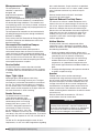
Microprocessor Control
The microprocessor
controller is specifically
designed and
programmed to optimize
the performance of
the unit with supplemental heating and cooling. This
option ensures that the outdoor air is conditioned to
the desired discharge conditions. The controller and
accompanying sensors are factory-mounted, wired and
programmed. Default settings are pre-programmed, but
are easily field-adjustable.
The microprocessor controller can be interfaced with
a Building Management System through LonWorks®,
BACnet®, or ModBus.
Please refer to the DDC Controller for Energy Recovery
Installation, Operation and Maintenance manual for
detailed information.
Unoccupied Recirculation Damper
(not offered with electric heat units)
The unoccupied recirculation option provides a
recirculation damper from the return air intake to the
supply airstream to reduce heating and cooling loads
when less ventilation is required. During the unoccupied
mode, the exhaust fan will remain off and the supply
air fan will operate with mode of tempering to maintain
unoccupied temperature set point.
Service Outlet
120 VAC GFCI service outlet ships loose for field
installation. Requires separate power source so power
is available when unit main disconnect is turned off for
servicing.
Vapor Tight Lights
Vapor tight lights provide light to each of the
compartments in the energy recovery unit. The lights
are wired to a junction box mounted on the outside of
the unit. The switch to turn the lights on is located in
the unit control center. The switch requires a separate
power source to allow for power to the lights when the
unit main disconnect is off for servicing.
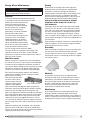
Smoke Detector
The Hochiki America DH-98 duct
smoke detector provides early
detection of smoke and products of
combustion present in air moving
through HVAC duct systems. The
DH-98-P is designed to prevent the
recirculation of smoke in areas by
the air handling systems, fans, and
blowers. Complete systems may be
shut down in the event of smoke detection. The Hochiki
America DH-98-P operate on 115 VAC, 24 VAC and 24
VDC.
The DH-98-P is designed and built to meet all local
requirements, as well as the NFPA regulations regarding
IMPORTANT
For the airflow monitoring device to perform as
intended, field calibration is required. Calibration of
the airflow monitoring device requires an independent
measurement of airflow and should be performed
when the system undergoes test and balance.

17
Energy Recovery Ventilator with Tempering
Start-Up Unit
DANGER
Electric shock hazard. Can cause injury or death.
Before attempting to perform any service or
maintenance, turn the electrical power to unit to OFF
at disconnect switch(es). Unit may have multiple
power supplies.
CAUTION
Use caution when removing access panels or other
unit components, especially while standing on a
ladder or other potentially unsteady base. Access
panels and unit components can be heavy and
serious injury may occur.
CAUTION
Do not operate without the filters and birdscreen
installed. They prevent the entry of foreign objects
such as leaves, birds, etc.
CAUTION
Do not run unit during construction phase. Damage to
internal components may result and void warranty.
WARNING
• Unit was factory tested. All blowers and fans are
set-up to run correctly when supplied power. If
any one fan is running backwards or making loud
noises, immediately turn off the power. Switch two
leads on the incoming power to the disconnect. This
will ensure proper operation of the unit. Failure to
comply may void the warranty.
• Do not jumper any safety devices when operating
the unit. This may damage components within or
cause serious injury or death.
SPECIAL TOOLS REQUIRED
• Voltage Meter (with wire probes)
• Amperage Meter
• Pressure Gauges – (refrigerant)
• Tachometer
• Thermometer
• U-tube manometer or equivalent
Start-Up Procedure
The unit will be in operational mode during start-up. Use
necessary precautions to avoid injury. All data must be
collected while the unit is running. In order to measure
volts and amps, the control center door needs to be
open and the unit energized.
• Make sure Pre-Start-Up checklist is complete.
• Jumper R to G to enable unit. Jumper R to Y1 and R
to Y2 to enable cooling and R to W1 to enable heat
for units without microprocessor.
• Turn the disconnect on. Make sure all fans are
rotating the correct direction.
• Allow the unit to run until the refrigerant system
stabilizes. Approximately 10-15 minutes.
Voltage Imbalance
In a three-phase system, excessive voltage imbalance
between phases will cause motors to overheat and
eventually fail. Maximum allowable imbalance is 2%.
To determine voltage imbalance, use recorded voltage
measurements in this formula.
Key: V1, V2, V3 = line voltages as measured
VA (average) = (V1 + V2 + V3) / 3
VD = Line voltage (V1, V2 or V3) that
deviates farthest from average (VA)
Formula: % Voltage Imbalance = [100 x (VA-VD)] /VA

18
Energy Recovery Ventilator with Tempering
Line Voltage. Check at unit disconnect.
L1-L2 Volts L2-L3 Volts L1-L3 Volts
Motor Amp Draw
Supply Motor Amps L1 Amps L2 Amps L3 Amps
Exhaust Motor Amps L1 Amps L2 Amps L3 Amps
Fan RPM
Correct fan rotation direction?
Supply Fan RPM Supply Fan Yes / No
Measured Airflow CFM
Exhaust Fan RPM Exhaust Fan Yes / No
Measured Airflow CFM
Energy Wheel Motor
L1 Amps L2 Amps L3 Amps
Heating System / Electric Heat
Pre-Heater L1-L2 Volts L2-L3 Volts L1-L3 Volts
L1 Amps L2 Amps L3 Amps
Temp. Rise
Post-Heater L1-L2 Volts L2-L3 Volts L1-L3 Volts
L1 Amps L2 Amps L3 Amps
Temp. Rise
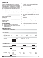
Every installation requires a comprehensive start-up
to ensure proper operation of the unit. As part of that
process, the following checklist must be completed and
information recorded. Starting up the unit in accordance
with this checklist will not only ensure proper operation,
but will also provide valuable information to personnel
performing future maintenance. Should an issue arise
which requires factory assistance, this completed
document will allow unit experts to provide quicker
resolve. Qualified personnel should perform start-up to
ensure safe and proper practices are followed.
Unit Model No. __________________________________
Unit Serial No. ____________________________________
Energy Wheel Serial Number _______________________
Start-Up Date ____________________________________
Start-Up Personnel Name _________________________
Start-Up Company ________________________________
Phone Number ___________________________________
Pre Start-Up Checklist
Disconnect and lock-out all power switches.
Remove any foreign objects that are located in the
energy recovery unit.
Check all fasteners, set-screws, and locking collars
on the fans, bearings, drives, motor bases and
accessories for tightness.
Check fan rotation.
Rotate the fan wheels and energy recovery wheels
by hand and ensure no parts are rubbing.
Check the fan belt drives for proper alignment and
tension.
Filters can load up with dirt during building
construction. Replace any dirty pleated filters and
clean the aluminum mesh filters in the intake hood.
Verify that non-motorized dampers open and close
properly.
Check the tightness of all electrical wiring
connections.
Verify control wire gauge.
Verify diameter seal settings on the energy recovery
wheel.
Verify proper drain trap installation.
Inspect all coils within the unit. Fins may get
damaged in transit or during construction. Carefully
straighten fins with a fin comb.
Start-Up Checklist
Pre Start-Up

19
Energy Recovery Ventilator with Tempering
Frost Control Application / Operation Section: Setting Factory Default
Yes No Frost Control set point 5°F
Differential 2°F
Timer Refer to IOM
Yes No Frost Control Modulating Refer to IOM
Economizer Application / Operation Section:
Yes No Economizer (temperature)
Set point 65°F
Offset 20°F
Differential 2°F
Yes No Economizer (enthalpy)
Set point B
Yes No Economizer (modulating) Refer to IOM
Optional Accessories Section: Operational
Yes No Wheel Rotation Sensor
(
1
⁄8 in. from wheel)
Yes No N/A
Yes No OA Dirty Filter Sensor Yes No N/A
Yes No EA Dirty Filter Sensor Yes No N/A
Yes No CO
2
Sensor Yes No N/A
Yes No Service Outlet Yes No N/A
Yes No Vapor Tight Lights Yes No N/A
Yes No Remote Control Panel Yes No N/A
Variable Frequency Drives Section: Operational
Yes No Blower VFDs Yes No N/A
Yes No Wheel VFD Yes No N/A
Damper Section: Operational
Yes No Outdoor Air Damper Yes No N/A
Yes No Exhaust Air Damper Yes No N/A
Yes No Night Setback Damper Yes No N/A
Outdoor Air Monitoring:
Yes No Field calibrated.
Optional Accessories Checklist
Refer to the respective sections in this Installation, Operation and Maintenance Manual for detailed information.
Refer to wiring diagram in unit control center to determine what electrical accessories were provided.

20
Energy Recovery Ventilator with Tempering
Start-Up Components
Energy Wheel
The energy wheel is installed in the unit’s airstream with
one half of the wheel in the intake airstream and one
half in the return airstream. Air leakage between the two
airstreams has to be kept to a minimum and the wheel
has air seals that must be adjusted for that purpose.
The seals must be adjusted at time of start-up.
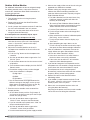
Drive Belt
Inspect the drive belt. Make sure the belt rides smoothly
in the pulley and around the outside of the wheel. Note
the directional arrow and data information shown in the
image.
Adjust the Air Seals
The first step in wheel seal adjustment is to make sure
the unit power supply is locked out. Disconnect the
wiring to the wheel module and pull the wheel cassette
out of the cabinet on its tracks. Large cassettes are
not removable. Then slowly
rotate the wheel by hand to
make sure there is no binding
or misalignment. The wheel
should rotate smoothly and
should not bind.
There is a perimeter seal
located around the outside
of the wheel and a diameter
seal across the face of the
wheel on both sides. Check to
make sure that all air seals are
secure and in good condition.
Adjust the air seals by
loosening all the air seal
retaining screws on the
bearing support (see image for
reference). Using a piece of
paper as a feeler gauge, adjust
the seals so they almost touch
the face of the wheel while
tugging slightly on the paper. When the wheel is rotated,
there should be a slight tug on the paper. Tighten the
screws, repeat the steps on the other set of seals.
Push the wheel cassette back into the unit and plug
in the power connector. Turn the main power supply
back on and then observe the operation of the wheel by
opening the wheel access door slightly. Remove filters if
necessary to observe the wheel.
Fans
The unit contains a double inlet airfoil fan and should be
checked for free rotation. If any binding occurs, check
for concealed damage and foreign objects in the fan
housing. Be sure to check the belt drives per the start-
up recommendations in the Fan Belt Drive section.
Centering of the fan wheel can be accomplished by
loosening the wheel hub set screw and moving the
wheel to the desired position.
Fan Performance Modifications
Due to job specification revisions, it may be necessary
to adjust or change the sheave or pulley to obtain the
desired airflow at the time of installation. The start-up
technician must check blower amperage to ensure that
the amperage listed on the motor nameplate is not
exceeded. Amperage to be tested with access doors
closed and ductwork installed.
Fan Belt Drives
The fan belt drive components, when supplied by
manufacturer, have been carefully selected for the
unit’s specific operating condition. Utilizing different
components than those supplied could result in unsafe
operating conditions which may cause personal injury or
failure of the following components:
• Fan Shaft • Bearings • Motor
• Fan Wheel • Belt
Tighten all fasteners and set screws securely and realign
drive pulleys after adjustment. Check pulleys and belts
for proper alignment to avoid unnecessary belt wear,
noise, vibration and power loss. Motor and drive shafts
must be parallel and pulleys in line (see diagrams in Belt
Drive Installation section).
Bearing Support Bar
Showing air seal assembly
tRet
aain
ng
in
Scr
cr
ews
s
Label showing
cassette serial number
and date code
Bearing Support
Adjustable
Air Seals
Drive Belt
Drive Pulley
CAUTION
When operating conditions of the fan are to be
changed (speed, pressure, temperature, etc.), consult
manufacturer to determine if the unit can operate
safely at the new conditions.
Page is loading ...
Page is loading ...
Page is loading ...
Page is loading ...
Page is loading ...
Page is loading ...
Page is loading ...
Page is loading ...
Page is loading ...
Page is loading ...
Page is loading ...
Page is loading ...
Page is loading ...
Page is loading ...
Page is loading ...
Page is loading ...
-
 1
1
-
 2
2
-
 3
3
-
 4
4
-
 5
5
-
 6
6
-
 7
7
-
 8
8
-
 9
9
-
 10
10
-
 11
11
-
 12
12
-
 13
13
-
 14
14
-
 15
15
-
 16
16
-
 17
17
-
 18
18
-
 19
19
-
 20
20
-
 21
21
-
 22
22
-
 23
23
-
 24
24
-
 25
25
-
 26
26
-
 27
27
-
 28
28
-
 29
29
-
 30
30
-
 31
31
-
 32
32
-
 33
33
-
 34
34
-
 35
35
-
 36
36


Greenheck 460945 ERT Operating instructions
- Category
- Split-system air conditioners
- Type
- Operating instructions
Ask a question and I''ll find the answer in the document
Finding information in a document is now easier with AI
Related papers
-
Greenheck 468410 SAF Operating instructions
-
-
Greenheck XG-XG-Fan User manual
-
-
-
-
-
-
-
Other documents
-
Broan Clip on Damper Kit Installation guide
-
 BV BV-RH-01 User manual
-
 valent VX Series Reference guide
-
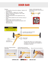 Super Vac Door Bar Hanger User manual
-
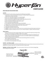 Hyper Fan 701405 User manual
-
Mark ERV1000 Technical Manual
-
Reznor XAWU Installation guide
-
-
 RenewAire Yaskawa VFD Owner's manual
-
Audiovox MCS Owner's manual


