Page is loading ...

VCIOM-16362-EN 21/05Emerson.com/FinalControl © 2021 Emerson. All Rights Reserved.
KTM VIRGO SERIES E & U TOP ENTRY TRUNNION BALL VALVE
INSTALLATION, OPERATION AND MAINTENANCE INSTRUCTIONS
Before installation these instructions must be fully read and understood
TABLE OF CONTENTS
1. Scope .............................................................. 1
2. Receipt, handling and storage...................... 1
3. Installation ..................................................... 3
4. Operation ....................................................... 4
5. Gear operator instructions ........................... 5
6. Emergency sealant injection system ........... 6
7. Preventive / periodic maintenance .............. 7
8. Possible misuse of ball valve ....................... 7
9. Troubleshooting ............................................ 8
10. Ordering spares............................................. 8
11. Disassembly and re-assembly
(EL and UL series) ......................................... 9
12. Body cavity relief operation ........................ 15
13. Gland packing assembly procedure .......... 15
14. Recommended tightening torques for
fasteners and plugs .................................... 16
15. Service of valves with API monogram ........ 17
16. Information for PED 2014/68/EU
compliant valve ............................................ 17
17. Warranty ...................................................... 18
18. Factory address for correspondence ......... 18
1 SCOPE
This manual is provided to ensure proper
installation, operation and maintenance for
KTM Virgo series Top Entry Trunnion Ball
valve, manufactured and supplied by Emerson
(Applicable to Soft / Metal seated, Cast, EL, UL
subseries.)
WARNING
Always use Personal Protective Equipment (PPE)
when carrying out above activities.
2 RECEIPT, HANDLING AND STORAGE
• Identify the valve contained in the box using
the packing list fixed on the box.
• While loading and unloading the box, check
for handling instructions/symbols marked
on the box and handle the box accordingly.
Ensure lifting of valve box in upright position
using fork lift as shown in Figure 1. Do not
drag the box.
• Before removing the valve from the box,
ensure valve is not fastened/fixed inside the
box with wooden battens and bolts which are
provided to prevent the valve from toppling or
moving inside the box during transportation.
• Remove the valve from the box using proper
D-Shackle or lifting hooks and straps. These
must be sized depending upon the weight
that must be lifted at lifting points (lifting
lugs) provided on valve as shown in Figure 2.
Do not use chains or hooks in contact with
the machined or painted surfaces.
FIGURE 1
Typical box and lifting position
Top support
Bottom support
Lift
Lift
Swing
Forklift lifting forks
near bottom support
FIGURE 2

2
KTM VIRGO SERIES E & U TOP ENTRY TRUNNION BALL VALVE
INSTALLATION, OPERATION AND MAINTENANCE INSTRUCTIONS
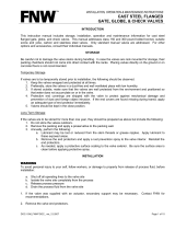
• If lifting lugs are not provided on the valve,
hold the valve with lifting strap around neck
area and gently lift it as shown in Figure 3.
Ensure the lifting strap is sized appropriately
for the weight that must be lifted and is
holding the neck area of valve firmly, to
prevent damages.
WARNING
• If the valve is supplied with an operator
(gear operator or actuator) do not use the
operator or the operator lifting lugs to lift the
valve assembly.
• For stem extension valve, use proper support
as shown in Figure 4 to prevent toppling
of valve.
• During handling, pay attention to prevent
any damage to the flange faces, butt weld
ends, operator, auxiliary fittings and piping
(as applicable). Do not drag the valve during
handling.
• The identification of the valve is given on the
body or on the nameplate or both. (Figure 5).
• If a tag number is specified by the customer,
identify the valve using tag number stamped
on the name plate or tag plate affixed to
the valve.
Lifting
straps
Body marking
Name plate
Size
matl
heat no.
WARNING
Do not lift from the
top flange of stem
extension
Always use lifting
hooks for lifting of
stem extension
Provide proper
support from here
to prevent toppling
FIGURE 3
FIGURE 5
FIGURE 4
• After removing from box, always store the
valve under roof and in a dry and clean
atmosphere, protected from rain and storm.
• Always place the valve on ‘soft’ surface like
rubber sheets or wooden planks free of dirt/
debris/hardware like nails and moisture to
avoid damage to the valve surfaces.
• Ensure that valve ends are covered with
protective end caps. Do not remove any
protection from the valve during storage
period.
• In case of automated valve assembly, refer to
actuator/accessory manufacturer instructions
for handling and storage.
• Always keep the valve either in fully open
or fully closed position. Full open position
is preferred. The valve is normally shipped
in the full open position (exception is valve
with a ‘fail close’ spring return actuator
arrangement)

3
KTM VIRGO SERIES E & U TOP ENTRY TRUNNION BALL VALVE
INSTALLATION, OPERATION AND MAINTENANCE INSTRUCTIONS
3 INSTALLATION
WARNING
• To prevent personal injury or property
damage resulting from the bursting of
pressure retaining parts, be certain the
service conditions do not exceed the limits
given on name plate / tag plate of valve.
• Personal injury could result from packing
leakage. The valve packing was tightened
before shipment however; the packing might
require some readjustment to meet specific
service conditions.
• Check with your process or safety engineer
for any additional measures that must be
taken to protect against process media.
• Before valve installation, ensure that the
pipeline is free from dirt, debris, scale, weld-
slag etc. to prevent damage to the internal
trim parts and seals of the valve.
• Ensure that the valve end protectors are
removed and the valve ends and bore are
cleaned before installation.
• If mounting stand or support stand of valve is
provided on end flange they shall be removed
before installation on the pipeline (refer
Figure 6).
• Mounting/support stand is only for handling
and transportation and not for carrying piping
loads. Hence Emerson recommends to give
supports to the pipeline appropriately and
shall not exceed following recommendations.
- For sizes, up to DN 100 (NPS 4), support to
be provided at a distance of ‘2D’ to ‘3D’ from
both valve ends
- For sizes, DN 150 (NPS 6) and higher,
support to be provided at distance ‘D’ from
both valve ends, where ‘D’ is the nominal
diameter of pipeline.
•
For removing mounting/support stand from
valve assembly, lift the valve above ground level
by using appropriate material handling/lifting
equipment. Refer handling section of this IOM.
Loosen and remove the nuts from respective
mounting stand bolts/studs and remove the
stands. Fasten the nuts and bolts/studs only to
the mounting stand again and store the entire
set appropriately to reuse whenever required
for maintenance, storage etc.
• To reinstall the mounting/support stand on
valve, position the valve above ground level
by using appropriate material handling/lifting
equipment. Refer handling section of this
IOM. Loosen and remove the nuts and bolts/
FIGURE 6
FIGURE 7
Mounting stand attached to body flange
Support from overhead
Foot support (ground support)
REMOVE
Remove while installing the valve
studs from mounting stand set. Position the
stand aligning its holes with valve flange
holes and retighten the nuts with bolts/studs
as shown in Figure 6.
• Examples of valve support configurations are
shown in Figure 7.
• The valve should preferably be in fully open
condition during installation. Exception being
the 'fail close' valves.
• Never install the Valve with the Actuator
upside down on the pipeline, refer Figure 8.
FIGURE 8
WARNING
Do not mount in this
position

4
KTM VIRGO SERIES E & U TOP ENTRY TRUNNION BALL VALVE
INSTALLATION, OPERATION AND MAINTENANCE INSTRUCTIONS
Installation of valve in vertical pipeline or
horizontal stem
• Installation of valve in vertical pipeline:
- This design does not permit the valve
installation in vertical pipeline.
• Installation of valve with horizontal stem:
- This design does not permit the valve
installation with stem in horizontal or
inclined position. Only vertical position is
allowed.
4 OPERATION
• For lever operated valve, the lever is either
shipped loose or assembled with valve
depending upon the size of the valve / lever.
Rotation of lever in the clockwise direction
closes the valve and counterclockwise
rotation opens the valve.
• For gear operated valve, THE GEAR
OPERATOR OPEN / CLOSE ADJUSTMENT
HAS BEEN DONE PRIOR TO SHIPMENT AND
MUST NOT BE CHANGED. Rotation of hand
wheel in the clockwise direction closes the
valve and counterclockwise rotation opens
the valve.
• It is recommended that the valve should
be opened and closed slowly to prevent
hammering effect on the valve and pipeline.
• If the valve is not operating to fully open or
fully close position and/or leaking, do not
apply excessive force to operate the valve.
This can damage the valve internals and/or
the operator parts.
• Do not apply extra force using inappropriate
extensions to levers and handwheel like pipes
or bars.
Note: International standards typically
restrict the input force on lever/handwheel
rim to max. of 360N and the valves are
designed accordingly.
• For valve with pneumatic and gas actuator,
do not exceed the operating pressure of
actuator.
• Always use dry, moisture free air while
operating the valve with pneumatic actuator.

5
KTM VIRGO SERIES E & U TOP ENTRY TRUNNION BALL VALVE
INSTALLATION, OPERATION AND MAINTENANCE INSTRUCTIONS
5 GEAR OPERATOR INSTRUCTIONS
5.1 Assembly of gear operator with bracket
and coupling
• It is recommended that the valve should
be kept in upright position (stem vertical).
• Valve shall be fully open.
• Place the bracket over valve top mounting
flange and fasten it with suitable fasteners.
Refer to tables in Section 14 of this IOM for
recommended tightening torques.
• Fit the key in stem keyway slot and then
mount coupling over stem.
• Fit the key in the coupling keyway slot and
assemble the gear operator on the bracket
with suitable fasteners ensuring that gear
operator position indicator matches the
open position of the valve.
• Gear operator setting should be done as
given in Section 5.3.
5.2 Assembly of gear operator without
bracket and coupling
• It is recommended that the valve should
be kept in upright position (stem vertical).
• Valve shall be fully open.
• Fit the key in the stem keyway slot and mount
the gear operator on valve top mounting
flange and fasten it with suitable fasteners
ensuring that gear operator position indicator
matches the open position of the valve.
Refer to tables in Section 14 of this IOM
for recommended tightening torques.
• Gear operator setting to be done as given
in Section 5.3.
5.3 Procedure for gear operator setting
CAUTION
If the valve has been supplied by Emerson with
the gear operator assembled on the valve -
open / close adjustment has been done prior
to shipment and must not be changed. In case
of gear operator replacement or mounting of
new gear operator on bare shaft valve, the steps
below shall be followed.
• Figure 11 shows the open and close positions
of position indicator, adjustment bolts and
lock nuts.
• Loosen the lock/check nut and unscrew
both left and right side bolt by minimum
one rotation.
• Match ball bore with valve bore. Fully tighten
the right-side bolt and then tighten the lock
nut.
• Rotate the ball by 90 degrees. Fully tighten
the left-side bolt and then tighten the
lock nut.
5.4 Possible orientations of gear operator
Figure 12 below illustrates the two possible
orientations for a gear operator when
assembled together with the series EL and UL
- Top entry Soft / Metal Seated Trunnion Ball
Valve
FIGURE 9
FIGURE 10
Handwheel
Handwheel
Position
indicator
Position
indicator
Gear operator
Gear operator
Coupling key
Stem key
Stem key
Stem
Coupling
Bracket
Assembly with bracket and coupling
Assembly without bracket and coupling
FIGURE 11
Open
position
Close
position
Adjust right bolt for open position
Adjust left bolt for close position
Lock nut / check nut
Gear operator setting
FIGURE 12
Orientation 1
Pipe line axis Pipe line axis
Orientation 2

6
KTM VIRGO SERIES E & U TOP ENTRY TRUNNION BALL VALVE
INSTALLATION, OPERATION AND MAINTENANCE INSTRUCTIONS
6 EMERGENCY SEALANT INJECTION SYSTEM
Typically provided on DN 150 (NPS 6) and larger
valves
• Emergency Sealant injection system is
provided on valve seat and/or stem packing
area to temporarily reduce seat leakage when
the valve is in the closed position or to reduce
packing leakage.
• Typically, for valve size DN 350 (NPS 14) and
above, 1 sealant injection fitting is provided
for stem and 2 fittings for each seat. For valve
sizes DN 300 (NPS 12) and below, 1 sealant
injection fitting is provided for stem and
1 fitting for each seat.
• This emergency sealant injection system
is to be used only when valve is not able to
achieve the desired shutoff due to damage /
wear and tear on the seats and seals and it is
not possible to take the valve off the line for
repair and maintenance.
• Always flush the sealant port with suitable
cleaner/solution, before injecting sealant.
Sealant / cleaning agents shall be selected
based on service fluid / condition.
References can be drawn from
manufacturers like Climax Lubricants and
Equipment Co
®
, Sealweld
®
etc.
Sealant injection fitting - Type A
(standard supply)
See Figure 13
Seat sealant injection
• Fully close the valve.
• Remove the fitting end cap and slide
giant buttonhead coupler (Climax
®
model
1699/1700) on sealant fitting. Inject sealant
into each of the sealant fitting. Injection
pressure shall be more than pipeline
pressure but shall not exceed 1.5 times the
pipeline pressure at operating temperature.
• Fully open the valve. Inject sealant into each
of the sealant fitting.
• Again, close the valve to uniformly distribute
the sealant over the ball surface.
• Repeat above steps multiple times until
desired sealing is achieved. Ensure last
injection is always made with valve in close
position.
Stem sealant injection
• Remove the fitting end cap and slide giant
buttonhead coupler on sealant fitting. Inject
sealant into the sealant fitting. Injection
pressure shall be more than pipeline
pressure but shall not exceed 1.5 times the
pipeline pressure at operating temperature.
• Cycle valve once to uniformly distribute the
sealant around the stem.
FIGURE 13
Sealant injection fitting - Type A (standard supply)
Check valve
Sealant fitting
Type A (marking)
Slot for sealant gun adapter
Body / bonnet / housing
End cap
Giant buttonhead coupler

7
KTM VIRGO SERIES E & U TOP ENTRY TRUNNION BALL VALVE
INSTALLATION, OPERATION AND MAINTENANCE INSTRUCTIONS
7 PREVENTIVE / PERIODIC MAINTENANCE
Preventive / periodic maintenance is essential
as the failure to do so may result in inadequate
performance of the valve or also failures like
seat leakage, environmental leakage, increased
torque, jerky operation etc.
All valves in operation should be periodically
inspected thoroughly to evaluate the condition
of ball, seats and seals as these parts are
subject to normal wear and tear. The frequency
of inspection depends upon the severity of
service conditions and location of the valve
and should be conducted during partial or
total shutdown.
Special attention is to be paid to inspect for
damage and / or wear due to corrosion or
erosion.
Periodic inspection of valve typically includes
following activities:
• Inspection for any visible defect or failure
such as packing or body joint leakage
• Tightening of bolts/nuts to recommended
torques
• Valve stroking to prevent jamming and
corrosion every six months
Section 11 describes the procedure for
disassembly and reassembly of the valve.
Once a valve is refurbished / repaired it should
undergo a complete set of tests to make sure
that the valve is fit to use for the intended
working conditions. Hydrostatic or Pneumatic
tests should be carried out as per the
specifications relevant to the valve.
Gear operators are packed with grease.
It is recommended that the grease should
be changed after approximately 5-7 years
if operated frequently or after 10-12 years
if operated infrequently. Contact factory for
appropriate grease grades if grease needs
to be changed.
8 POSSIBLE MISUSE OF BALL VALVE
Sr. no. Possible misuse Actions to prevent misuse
1 Exceeding the pressure and / or temperature limits of
the valve.
Do not exceed pressure and / or temperature limits mentioned on name plate affixed to the valve.
2 Valve material not suitable for service fluid. Check Tag number (as applicable) and ensure correct valve is used as per process diagram.
Verify valve material mentioned on Name plate is suitable with service fluid.
3 Use for control application. These ball valves are designed for on/off application and should not be used for control / throttling.
4 Mounting of valve upside down. Follow ‘Installation’ section of this document.
5 Wrong installation in case of uni-directional valve. Verify flow direction on valve body or on additional plate affixed to valve.
6 Use of improper actuator when customer automates
valve on site.
Contact factory for correct sizing of actuator.
7 Opening/closing of valve by using inappropriate
extensions like pipes/bars etc.
Operate valve only with levers, gear operator, hand wheel or actuator provided / recommended
by Emerson.
8 Any modification by customer in valve e.g. drilling,
tapping, change of valve ends etc.
Unauthorized modifications are not allowed. Modification voids warranty.
Contact factory if any such case arises.
9 Testing the valve with water without corrosion inhibitor. Corrosion inhibitor shall be used to prevent corrosion of valve components. Requirements of
international standards such as API 6D, API 598, BS EN 12266 etc. should be followed.
10 Inadequate draining and drying of valve after hydro test. When valves are hydro tested onsite, they shall be drained and dried completely before installing on
pipeline to prevent corrosion of parts and contamination of service fluid.
11 Not using lock open/close feature. Ensure to use this provision (as applicable) based on process requirement.
12 Improper long term storage. For long term storage and preservation of valves at site refer Emerson procedure QAC/KM-028.
Contact Factory.
13 Damage to valve fittings during handling. Follow handling instructions.

8
KTM VIRGO SERIES E & U TOP ENTRY TRUNNION BALL VALVE
INSTALLATION, OPERATION AND MAINTENANCE INSTRUCTIONS
Problem Possible cause Remedy
Leakage across closed valve 1. Damaged ball surface. 1. Refurbish or replace the ball.
2. Damaged seats / seat seals. 2. Refurbish or replace seats.
Replace seat seals.
3. Ball not closed fully. 3. Check and reset ball.
Open/close settings.
4. Seat not moving freelyresulting in inadequate contact
between ball and seat.
4. Open valve, check for accumulation of dirt, debris,
corrosion between seat and body, clean and re-assemble.
Valve too hard to operate / valve
torque too high / stick-slip operation
1. Damaged seats / seat seals / ball. 1. Refurbish or replace the seats / seat seals / ball.
2. Seat not moving freely due to accumulation of dirt,
debris, corrosion between seat and body or seat and ball.
2. Open valve, clean and reassemble.
3. Operator not sized properly, damaged operator parts. 3. Select correct operator and replace.
4. Actuator not sized properly, damaged actuator
parts, insufficient input air/gas pressure to actuator,
restriction/clogging of actuator vent.
4. Select correct actuator and replace. Check input air
supply, clean actuator vent.
Leakage through stem 1. Loose gland fasteners. 1. Tighten the fasteners.
2. Damaged stem, stem sealing surface. 2. Refurbish or replace the stem.
3. Damaged stem seal. 3. Replace the stem seal.
4. Accumulation of dirt, debris, corrosion between stem
and housing.
4. Open valve, clean and reassemble.
Leakage through body to bonnet
joint; bonnet to housing joint
1. Damaged seal/gasket. 1. Replace seal/gasket.
2. Relaxation of joint fasteners. 2. Retighten the fasteners evenly in criss-cross manner.
3. Accumulation of dirt, debris, corrosion between body
and bonnet.
3. Open valve, clean and reassemble.
Leakage through drain, vent and
sealant fittings.
1. Loosening of fittings. 1. Retighten. If leakage persists may require fresh thread
sealant or replacement of fitting.
WARNING: Do not remove fittings when valve / body
cavity is under pressure.
9 TROUBLESHOOTING
Size
Available on name plate or body of the valve
Class
Available on name plate or body of the valve
Batch number / serial number
Available on name plate or body of the valve
Manufacturing date
Available on name plate or body of the valve
Part number
Available on general arrangement drawing
Part name
Available on general arrangement drawing
Purchase order number
Available on general arrangement drawing
10 ORDERING SPARES
When ordering spares, please furnish the following information.

9
KTM VIRGO SERIES E & U TOP ENTRY TRUNNION BALL VALVE
INSTALLATION, OPERATION AND MAINTENANCE INSTRUCTIONS
11 DISASSEMBLY AND RE-ASSEMBLY
Sections
11.1 Warnings
11.2 Notes
11.3 Series EL and UL – Top entry Soft /
Metal Seated Trunnion Ball Valve
Construction: One-Piece
Type: Integral trunnion
11.3.1 Disassembly procedure
11.3.2 Re-assembly procedure
11.3.3 General arrangement view
11.3.4 Assembly tool
11.1 Warnings
For removal of valve from pipeline, disassembly,
re-assembly
• Pay attention to prevent personal injury or
equipment damage from sudden release of
process pressure or uncontrolled movement
of parts.
• Always wear PPE like protective gloves,
safety shoes, helmet, clothing, eyewear and
other PPE as mandated by site/project when
performing any maintenance operations to
prevent personal injury.
• Do not remove the operator from the valve
while the valve is still pressurized.
• In case of an actuated valve, before removal
of actuator, disconnect any operating lines
providing air pressure, electric power, or a
control signal to the actuator. Be sure the
actuator cannot accidently open or close the
valve.
• In case of spring return actuators ensure that
the spring is at its uncompressed position.
• Use bypass valves or completely shut off the
process to isolate the valve from process
pressure. Relieve process pressure from both
sides of the valve. Drain the process media
from both sides of the valve.
• Ball valves can retain pressure and process
fluid in cavity even after process pressure has
been removed from both sides of the valve.
Relieve this pressure before disassembling
or removing the valve from the line. Take
additional care if the process fluid is hot,
flammable, caustic, or hazardous.
• Carefully secure the valve in an upright
position. The roundness of the flanges and
valve body allow it to easily roll from side-
to-side. The combined weight of the valve
and actuator assembly could cause injury
or property damage when falling to the side.
• Use lock-out procedures to be sure that the
above measures stay in effect while you work
on the equipment.
• Exercise caution when working on the valve
stem packing as it may contain process
fluids that are pressurized, even when the
valve has been removed from the pipeline.
Process fluids may spray out under pressure
when removing the packing hardware or
packing rings.
• Prevent injury by keeping hands, tools and
other objects away from the ball while
stroking the valve.
• Check with your process or safety engineer
for any additional measures that must be
taken to protect against process media.

10
KTM VIRGO SERIES E & U TOP ENTRY TRUNNION BALL VALVE
INSTALLATION, OPERATION AND MAINTENANCE INSTRUCTIONS
11.2 Notes
• Ensure clean environment during
disassembly and re-assembly of valve.
• Use appropriate material handling / lifting
equipment. Refer handling section of
this IOM.
• Prior to disassembly, it is recommended to
mark mating parts like body and bonnet,
bonnet and housing, gear operator or
actuator and ISO pad or housing to ensure
same orientation during re-assembly.
• Before disassembly, it is recommended to
keep the ball in fully closed position and then
remove the operator from valve assembly.
• Valve shall be positioned on clean and flat
surface as shown in Figure 14.
• It is recommended to use original spares.
- Graphite gaskets shall be replaced.
- Elastomer and plastomer seals can be
re-used, however it is recommended to
replace them to maximize valve service life.
• Protect every sealing surface from nicks,
dents and damages.
• Lubricate the o-ring and seals and lip seals
before re-assembly.
• During re-assembly, refer to tables in
Section 14 of this IOM for recommended
tightening torques.
• Assembly drawing shows the standard
configuration for valve with o-ring seals but
can be considered as a reference for lip-seal
configuration also.
FIGURE 14

11
KTM VIRGO SERIES E & U TOP ENTRY TRUNNION BALL VALVE
INSTALLATION, OPERATION AND MAINTENANCE INSTRUCTIONS
11.3 Series EL and UL - top entry soft / metal
seated trunnion ball valve
Construction: One-piece
Type: Integral trunnion
Refer Section 11.3.3 for general arrangement
view and location of parts.
11.3.1 Disassembly procedure
1. Position the valve with ball in closed position
as shown in Figure 15.
2. Slowly remove the vent / drain plug (20)
to relieve any residual pressure from the
body cavity.
3. Remove the stem key (9) from the stem (5).
4. Remove cap-screws (14a).
5. Remove ISO pad (8).
6. Unscrew and remove body nuts (13) from
body studs (12).
7. Screw an eyebolt inside the tapping provided
on the top surface of the bonnet and lift
the bonnet-housing sub-assembly. Ensure
that stem will not fall while lifting bonnet-
housing assembly.
8. If it is necessary to replace the stem gasket,
follow instructions 9 to 11 below. Otherwise
donot disassemble the stem-bonnet sub-
assembly and go to instruction no. 12.
9. Push the stem (5) out of its housing on the
bonnet (2).
10. Remove stem o-rings (10c) and backup
rings (if provided) from bonnet and then
remove graphite stem gasket (11a).
FIGURE 15
11. Remove stem thrust washer (22) from the
stem.
12. Insert the two hydraulic pistons inside body
cavity and clamp the external profile of the
spring holder ring (3a) (Refer assembly tool
view 11.3.4 and Figure 15.
13. Close the hydraulic pistons together to pull
the seat spring holder rings towards center
of the valve.
14. Remove spacer (3b) from both spring holder
rings. (Refer Figure 16).
15. Use the hydraulic pistons to push spring
holder ring (3a) back inside body recess.
16. Remove hydraulic pistons from body cavity.
17. Rotate the ball (4) to fully open position
using two eye bolts screwed on ball.
18. Remove the ball from the body (1) using eye
bolts.
19. Remove seat assembly (3, 3a, 3b) from body.
20. Remove the Bearing Retainer (7), ball
bushing (21) and ball thrust washer (23)
from the body if provided.
21. Remove seat (3) from the seat spring holder
ring (3a).
22. Remove o-rings (10a, 10b) and its back-up
ring (if present) from seat and seat spring
holder ring.
23. Remove all the springs (15) from the seat
spring holder ring.
FIGURE 16

12
11.3.2 Re-assembly procedure
1. Install all the springs (15) in spring holder
ring (3a) then put spacer (3b) on spring
holder ring and move till the end of spring
holder ring.
2. Assemble the spring holder ring over the
seat (3).
3.
Install seat o-ring (10a) and retainer o-ring
(10b) with backup ring (if provided) on seat (3).
4. Insert seat assemblies inside the body (1)
and push them till the end of the pocket in
the body.
5. Install bearing retainer (if not integral with
body) (7), ball bushing (21) and ball thrust
washer (23) inside body.
6. Insert ball (4) inside body using eye bolt
screwed on ball, such that ball is in the open
position.
7. Rotate the ball to fully closed position.
Remove eye bolts.
8. Insert anti-static spring (15a) in the central
hole of the ball.
9. Using hydraulic pistons, pull the two seat
assemblies towards the ball.
10. Move spacer (3b) in the groove provided on
spring holder ring (3a).
11. Remove hydraulic pistons from body.
12. If the stem was disassembled from housing,
follow instructions from 13 to 16 otherwise
go to Section 17.
13. Insert stem thrust washer (22) over the
stem (5).
14.
Insert stem o-rings (10c) along with backup
rings (10c) (if provided) inside the housing (6).
KTM VIRGO SERIES E & U TOP ENTRY TRUNNION BALL VALVE
INSTALLATION, OPERATION AND MAINTENANCE INSTRUCTIONS
15. Install o-ring (10d) and graphite gasket
(11b) between housing (6) and bonnet (2).
Now fasten the housing to bonnet using
fasteners (14).
16. Insert stem inside the bonnet and housing
with respect to ball in the closed position.
While inserting stem inside the housing,
the edges of keyway slot may damage the
o-rings. Hence take suitable protection like
wrapping stem keyway side with common
adhesive tape.
17. Install o-ring (10) and graphite gasket (11)
between bonnet and body and fasten the
assembly using fasteners (12 / 13).
18.
Install stem gasket (11a) inside housing and
then assemble the ISO pad (8) using cap
screw (14a) and pins (24). Install stem key (9).
19. Install the drain plug and vent plug and
injection fittings as applicable.

13
1
5
8
4
11
10a
9
2
10b
13
23
24
15
12
20
16a
6
11a
10c
10d
21a
15a
11b
3b
14
10
22
18
21
17
3
14a
27
7
16
3a
19
A
C
B
C
KTM VIRGO SERIES E & U TOP ENTRY TRUNNION BALL VALVE
INSTALLATION, OPERATION AND MAINTENANCE INSTRUCTIONS
11.3.3 General arrangement view
E and U series top entry ball valve
Construction: One-piece
Type: Integral trunnion
PARTS LIST
Item No. Part name
1 Body
2 Bonnet
3 Seat ring
3a Spring holder ring
3b Retainer ring
4 Ball
5 Stem
6 Housing
7 Bearing retainer
8 ISO pad
9 Stem key
10 Body o-ring
10a Seat o-ring
10b Grease retaining o-ring
10c Stem o-ring
10d Housing o-ring
11 Body gasket
11a Stem gasket
11b Housing gasket
12 Body studs
13 Body nuts
14 Housing capscrew
14a ISO pad capscrew
15 Springs
15a Antistatic spring
16 Stem grease fitting
16a Nipple
17 Seat grease fitting
18 Check valve
19 Vent bleeder valve
20 Drain plug
21 Ball bushing
21a Stem bushing
22 Stem thrust washer
23 Ball thrust washer
24 Pin
Item No. Part name
Stem detail B
SECTION C-C
Position Nr. 20
Drain plug detail
Position Nr. 19
Vent bleeder detail
Stem detail A

14
KTM VIRGO SERIES E & U TOP ENTRY TRUNNION BALL VALVE
INSTALLATION, OPERATION AND MAINTENANCE INSTRUCTIONS
11.3.4 Assembly tool view
Quantity Nr: 2 For maintenance 1 valve
Seat holder connection
Seat holder connection
Hydraulic piston double effect
Hydraulic quick coupling female ⅜"
Close Open

15
KTM VIRGO SERIES E & U TOP ENTRY TRUNNION BALL VALVE
INSTALLATION, OPERATION AND MAINTENANCE INSTRUCTIONS
12 BODY CAVITY RELIEF OPERATION
Single piston effect seat - self relieving seat
When seats are under pressure in pipeline,
upstream and downstream both, the resultant
thrust from pressure pushes the seat rings
towards the ball.
At the same time, pressure in the body cavity
creates a thrust that pushes the seat rings
away from the ball.
The single piston effect (SPE) permits the
automatic release of overpressure in the body
cavity when the valve is in the fully open or
closed position. In single piston effect design,
seat rings are thus “self-relieving”.
Double piston effect seat (DEP) - non relieving
type of seats
When seats are under pressure in pipeline,
upstream and downstream both, the resultant
thrust from pressure pushes the seat rings
towards the ball.
Also, pressure in the body cavity creates a thrust
that pushes the seat rings towards the ball.
When the valve is designed with double piston
effect (DPE), self-relieving does not occur and
hence PR (pressure relief) valve is mandatory
with pre-setting to avoid over pressure building
in the cavity.
13 GLAND PACKING ASSEMBLY PROCEDURE
1.
In case of packing contain braided graphite, it
shall be placed at bottom and top. Position of
packing arrangement such that the oblique
cut of these braided graphite is 180° apart.
Refer Figure below for appropriate
arrangement for die molded and for VEE type
packing.
2. Place the gland into the housing and disk
spring (for VEE type packing) and the cap
screw / hex bolt.
3. Hand tighten cap screw / hex bolt in
crisscross pattern.
4. Tighten gland cap screws / hex bolt in
crisscross pattern by using 25% torque as
specified in Section 14 against mentioned
fasteners material.
5. Ensure no bottoming up of gland or
otherwise one ring needs to be added in
packing set.
6. Verify that the gland top surface is at equal
depth from top face of housing.
NOTE
Full tightening of screws shall be done during
performance testing depending on leakage observed.
FIGURE 18
Square/rectangular type stem packing arrangement
Stem
FIGURE 19
VEE type stem packing arrangement
Gland
Braided
gaskets
One packing set
Die molded gaskets
Gland bolt
Disk
springs
Gland
Stem
Braided
gaskets
One packing set
VEE type packing set

16
M8 1.25 15 6 18 20 16 9 3 11 12 10
M10 1.50 30 11 36 40 32 18 7 21 24 19
M12 1.75 52 19 62 69 55 31 12 37 40 33
M14 2.00 83 31 99 108 88 49 18 58 64 52
M16 2.00 126 47 150 165 134 74 28 88 97 79
M18 2.50 174 65 207 228 185 103 38 123 135 110
M20 2.50 243 91 289 318 258 143 53 143 187 152
M22 2.50 327 122 327 428 348 191 71 191 250 203
M24 3.00 415 155 415 544 441 245 91 200 320 261
M27 3.00 601 224 492 787 639 351 131 287 459 373
M30 3.50 814 303 511 1066 866 477 178 299 625 507
M33 3.50 1097 409 688 1436 1167 639 238 401 836 680
M36 4.00 1410 526 884 1845 1500 824 307 517 1078 876
M39 4.00 1810 675 1135 2370 1925 1052 392 660 1377 1119
M42 4.50 2241 835 1406 2934 2384 1306 487 819 1710 1389
M45 4.50 2780 1036 1744 3639 2957 1613 601 1012 2112 1716
M48 5.00 3348 1248 2100 4383 3561 1948 726 1222 2571 2072
M52 5.00 4298 1602 2696 5626 4572 2488 927 1561 3257 2646
M56 5.50 5343 1991 3352 6995 5683 3098 1155 1943 4056 3295
M60 5.50 6624 2469 4155 8671 7046 3824 1425 2399 5006 4067
KTM VIRGO SERIES E & U TOP ENTRY TRUNNION BALL VALVE
INSTALLATION, OPERATION AND MAINTENANCE INSTRUCTIONS
14 RECOMMENDED TIGHTENING TORQUES
FOR FASTENERS AND PLUGS
NOTES
1. Ensure that all the nuts/bolts are tightened to the
torque values as specified in below tables.
2. Torque values for carbon and low alloy steel
material are for dry and non-lubricated fasteners.
3. Torque values for austenitic stainless steel
material are with anti-seize lubricant.
4. Apply pipe thread sealant to the threads of the
drain and vent plugs.
5. 1 Nm = 0.737 ft·lb
FOR METRIC SERIES (Nm)
Thread size
(Metric) Pitch
Non-coated bolts / nuts Coated bolts / nuts
Low resistance bolt /
stud material
High resistance bolt /
stud material
Low resistance bolt /
stud material grade
High resistance bolt /
stud material
L7M, B7M
B8M
Class 1
B8M
Class 2 L7, B7 Gr 660 L7M, B7M
B8M
Class 1
B8M
Class 2 L7, B7 Gr 660

17
5
/
16" 18 15 6 18 20 16 10 4 12 12 11
⅜" 16 26 10 22 34 28 15 6 18 20 16
½" 13 61 23 73 80 65 37 14 44 47 39
⅝“ 11 118 44 141 155 126 71 26 85 92 76
¾“ 10 206 77 245 270 219 122 45 145 160 130
⅞“ 9 328 122 328 429 349 194 72 194 255 206
1“ 8 488 182 488 639 519 289 108 289 378 307
1⅛“ 8 706 263 578 925 751 414 154 339 544 440
1¼“ 8 981 366 803 1285 1043 571 213 467 750 607
1⅜“ 8 1320 492 933 1727 1404 763 284 479 1002 812
1½“ 8 1727 644 1083 2261 1837 994 370 624 1305 1057
1⅝“ 8 2211 824 1387 2894 2352 1266 472 794 1527 1347
1¾“ 8 2777 1035 1742 3636 2954 1585 591 994 2080 1686
1⅞“ 8 3433 1280 2153 4493 3651 1952 728 1224 2563 2076
2“ 8 4183 1559 2624 5476 4449 2373 884 1489 3114 2524
2¼“ 8 5997 2235 3762 7851 6379 3375 1258 2117 4418 3590
2½“ 8 8271 3083 5188 10828 8797 4635 1728 2907 6068 4930
2¾“ 8 11117 4144 6973 14591 11824 6208 2314 3894 8148 6603
3“ 8 14481 5397 9084 19007 15403 8064 3006 5058 10583 8577
3¼“ 8 18462 6881 11581 24232 19637 10256 3823 6433 13461 10909
3½“ 8 23114 8615 14499 30336 24585 12812 4775 8037 16817 13627
3¾“ 8 28485 10617 17868 37388 30298 15762 5875 9887 20688 16765
⅜” NPT 18 61
½" NPT 14 68
¾" NPT 14 75
1” NPT 11½ 88
KTM VIRGO SERIES E & U TOP ENTRY TRUNNION BALL VALVE
INSTALLATION, OPERATION AND MAINTENANCE INSTRUCTIONS
FOR IMPERIAL SERIES (Nm)
Thread size
(Inch) TPI
Non-coated bolts / nuts Coated bolts / nuts
Low resistance bolt /
stud material
High resistance bolt /
stud material
Low resistance bolt /
stud material grade
High resistance bolt /
stud material
L7M, B7M
B8M
Class 1
B8M
Class 2 L7, B7 Gr 660 L7M, B7M
B8M
Class 1
B8M
Class 2 L7, B7 Gr 660
FOR NPT PLUG THREADS
Plug size Thread per inch Approx. torque (Nm)
The year of manufacture Refer name plate affixed to the valve
Essential maximum / minimum allowable limits Refer name plate affixed to the valve
The normal size for piping DN Refer name plate affixed to the valve
Test pressure applied in bar and date Refer tag plate affixed to the valve
Tare mass in kg Refer tag plate affixed to the valve
The fluild group Refer tag plate affixed to the valve
16 INFORMATION FOR PED 2014/68/EU COMPLIANT VALVE
NOTES
1. Torque values given for NPT threads are only for
reference, it may change depending upon accuracy
of thread profile, sealing requirement, nature of
the sealant used etc.
2. As a general guideline, after hand-tight
engagement, tighten 1-3 full turns so that you get
'leak proof' joint.
15 SERVICE OF VALVES WITH API MONOGRAM
In case of repair and service of “API monogram” valve, service engineer shall consult Head- QA
for any further actions.

18
VCIOM-16362-EN © 2021 Emerson Electric Co. All rights reserved 05/21. KTM is a mark owned by one of the companies in the Emerson Automation Solutions business
unit of Emerson Electric Co. The Emerson logo is a trademark and service mark of Emerson Electric Co. All other marks are the property of their prospective owners.
The contents of this publication are presented for informational purposes only, and while every effort has been made to ensure their accuracy, they are not to be construed
as warranties or guarantees, express or implied, regarding the products or services described herein or their use or applicability. All sales are governed by our terms and
conditions, which are available upon request. We reserve the right to modify or improve the designs or specifications of such products at any time without notice.
Emerson Electric Co. does not assume responsibility for the selection, use or maintenance of any product. Responsibility for proper selection, use and maintenance of
any Emerson Electric Co. product remains solely with the purchaser.
Emerson.com/FinalControl
KTM VIRGO SERIES E & U TOP ENTRY TRUNNION BALL VALVE
INSTALLATION, OPERATION AND MAINTENANCE INSTRUCTIONS
17 WARRANTY
Our liability in respect of any defect in or
failure of the goods supplied or for any loss,
injury or damage attributable thereto is limited
to making good by replacement or repair
defects which under proper use appear therein
and arise solely from faulty materials and
workmanship within a period of 18 calendar
months after the original goods shall have
been first dispatched or 12 calendar months
from the date of commissioning, whichever is
earlier provided that such defective parts are
returned free to our works for examination.
The undertaking shall exclude any and every
other obligation.
CAUTION
Emerson does not assume responsibilities for
any liabilities/damages arriving out of wrong
application of its valve, or imprudent operations
carried out by inexperienced operators, or which
does not comply with this manual, or instructions
provided by Emerson.
The valve shall be appropriately used for the
purpose they are built, or applications they
are supplied. Use of standard valve for special
applications is not recommended unless it has
been communicated and agreed to by Emerson.
Valve shall be operated and maintained strictly
in accordance with the procedures. Operation
or maintenance outside these procedures
constitutes abuse of the product and voids all
warranty and claims.
18 FACTORY ADDRESS FOR CORRESPONDENCE
Emerson Process Management (India)
Private Limited
(Manufacturing Regional Sales Office)
277 / 278 Hinjewadi Phase II, Maan (Mulshi)
Pune - 411 057, INDIA
Phone: +91 20 6674 4000
Fax: +91 20 6674 4021
www.emerson.com
Emerson Process Management (India)
Private Limited
Plot No. C1
Talegaon Industrial Area
Phase 2, Talegaon MIDC,
Mindewadi,
Taluka - Mawal,
Pune - 410 506, INDIA
Phone: +91 21 1461 1100
www.emerson.com
Emerson Automation Solutions
(Regional Sales Office)
10225 Mula Road, Suite 130
Stafford, TX 77477, USA
Phone: +1 281 933 3100
Fax: +1 281 933 3110
www.emerson.com
/