Anderson Greenwood 4142HF Pressure Relief Valve Owner's manual
- Type
- Owner's manual
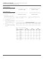
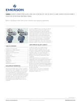
Anderson Greenwood 4142HF Pressure Relief Valve is employed in gas/vapor service applications for low pressure storage tanks, vessels, or applications requiring low-pressure protection with high-capacity flow requirements. This product helps prevent damage to the tank and also prevents the tank’s contents from escaping, ensuring the safety of personnel and the surrounding environment. The Anderson Greenwood 4142HF PRV is a direct-acting vent valve based on the weight of the pallet to keep the valve closed. When tank pressure acting on the seat sealing area equals the opposing force acting on the pallet, the valve is on the threshold of opening. Any further increase in pressure will cause the pressure pallet to lift, allowing the contents of the tank to vent through the valve (out-breathing).
Anderson Greenwood 4142HF Pressure Relief Valve is employed in gas/vapor service applications for low pressure storage tanks, vessels, or applications requiring low-pressure protection with high-capacity flow requirements. This product helps prevent damage to the tank and also prevents the tank’s contents from escaping, ensuring the safety of personnel and the surrounding environment. The Anderson Greenwood 4142HF PRV is a direct-acting vent valve based on the weight of the pallet to keep the valve closed. When tank pressure acting on the seat sealing area equals the opposing force acting on the pallet, the valve is on the threshold of opening. Any further increase in pressure will cause the pressure pallet to lift, allowing the contents of the tank to vent through the valve (out-breathing).


-
 1
1
-
 2
2
-
 3
3
-
 4
4
-
 5
5
-
 6
6
-
 7
7
-
 8
8
-
 9
9
-
 10
10


Anderson Greenwood 4142HF Pressure Relief Valve Owner's manual
- Type
- Owner's manual
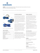
Anderson Greenwood 4142HF Pressure Relief Valve is employed in gas/vapor service applications for low pressure storage tanks, vessels, or applications requiring low-pressure protection with high-capacity flow requirements. This product helps prevent damage to the tank and also prevents the tank’s contents from escaping, ensuring the safety of personnel and the surrounding environment. The Anderson Greenwood 4142HF PRV is a direct-acting vent valve based on the weight of the pallet to keep the valve closed. When tank pressure acting on the seat sealing area equals the opposing force acting on the pallet, the valve is on the threshold of opening. Any further increase in pressure will cause the pressure pallet to lift, allowing the contents of the tank to vent through the valve (out-breathing).
Ask a question and I''ll find the answer in the document
Finding information in a document is now easier with AI
Related papers
-
Anderson Greenwood 4020HP Pressure and Vacuum Relief Valve Owner's manual
-
-
-
-
-
-
-
-
-
Other documents
-
Custom Built Plastic Pallets 05000213 User manual
-
Targus APTA29 Datasheet
-
Emerson 5910C Anderson Greenwood Pressure Vacuum Relief Valve User manual
-
TESCOM Anderson Greenwood User guide
-
Cash Valve Type E-55 Pressure Reducing Valve Final-Line Gas Installation guide
-
-
-
 Varec Pressure and Vacuum Relief Valves Owner's manual
-
 Varec Pressure Relief Valves Series 2010B/2020B//3500B IOM Owner's manual
-
 Varec Pressure Relief Valves Series 7100B IOM Owner's manual


