UM DS-2CE71D0T-PIRL 072718NA
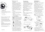
TurboHD
Turret Camera
DS-2CE71D0T-PIRL
User Manual
Thank you for purchasing our product. If there are any
questions, or requests, please contact the dealer.
This manual may contain technical incorrect places or
printing errors, and the content is subject to change
without notice. The updates will be added to the new
version of this manual. We will readily improve or update
the products or procedures described in the manual.
Regulatory Information FCC Information
Please take attention that changes or modification not
expressly approved by the party responsible for
compliance could void the user’s authority to operate the
equipment.
FCC Compliance: This equipment has been tested and
found to comply with the limits for a Class A digital device,
pursuant to part 15 of the FCC Rules. These limits are
designed to provide reasonable protection against harmful
interference when the equipment is operated in a
commercial environment. This equipment generates, uses,
and can radiate radio frequency energy and, if not
installed and used in accordance with the instruction
manual, may cause harmful interference to radio
communications. Operation of this equipment in a
residential area is likely to cause harmful interference in
which case the user will be required to correct the
interference at his own expense.
FCC Conditions
This device complies with part 15 of the FCC Rules.
Operation is subject to the following two conditions:
1. This device may not cause harmful interference.
2. This device must accept any interference received,
including interference that may cause undesired
operation.
EU Conformity Statement
This product and, if applicable, the supplied
accessories too are marked with “CE” and comply
therefore with the applicable harmonized
European standards listed under the Low Voltage Directive
2014/35/EU, the EMC Directive 2014/30/EU, the RoHS
Directive 2011/65/EU.
2012/19/EU (WEEE Directive): Products marked with this
symbol cannot be disposed of as unsorted
municipal waste in the European Union. For proper
recycling, return this product to your local supplier
upon the purchase of equivalent new equipment,