Elektror S-HP 265/33 Operating And Assembly Instructions Manual
- Category
- Measuring & layout tools
- Type
- Operating And Assembly Instructions Manual
This manual is also suitable for

Elektror airsystems gmbh
Hellmuth-Hirth-Strasse 2, D-73760 Ostfi ldern
Postfach 1252, D-73748 Ostfi ldern
Telefon +49 711 31973-0
Telefax +49 711 31973-5000
info@elektror.de
www.elektror.de
S-HP
Elektror Edel-
stahl-Hochdruck-
ventilatoren
Betriebs- und
Montageanleitung
DE
Elektror Stainless
Steel High
Pressure Blowers
Operating and
assembly
instructions
EN
S-HP 265/18, S-HP 265/33, S-HP 290/30
S-HP 335/30, S-HP 365/18, S-HP 380/30
S-HP 395/30, S-HP 470/35

2
DE
Betriebs- und Montageanleitung S-HP www.elektror.de
9016325 01.20/07
INHALT
1 ANGABEN ÜBER DIE MASCHINE
2 INFORMATIONEN ÜBER TRANSPORT,
HANDHABUNG UND LAGERUNG DER MASCHINE
3 INFORMATIONEN ÜBER DIE INBETRIEBNAHME
4 ANGABEN ZU BETRIEB UND VERWENDUNG
5 ANGABEN ZUR INSTANDHALTUNG
6 SICHERHEITSRELEVANTE INFORMATIONEN
ÜBER AUSSERBETRIEBNAHME UND ABBAU
7 HAFTUNG UND HAFTUNGSAUSSCHLUSS
8 EINBAUERKLÄRUNG NACH ANHANG II 1 B
9 EXPLOSIONSZEICHNUNG
10 ALLGEMEINE ERSATZTEILLISTE
11 TECHNISCHE DATEN
12 ANGABEN GEMÄß ERP DURCHFÜHRUNGS-
VERORDNUNG 327/2011
Diese Betriebs- und Montageanleitung muss dem Bedie-
nungspersonal jederzeit zugänglich sein. Lesen Sie die vor-
liegende Betriebs- und Montageanleitung vor Montage und
Inbetriebnahme des Ventilators sorgfältig durch.
Änderungen vorbehalten. Im Zweifelsfall ist eine Rückspra-
che mit dem Hersteller erforderlich. Diese Unterlage ist urhe-
berrechtlich geschützt. Sie darf ohne unsere ausdrückliche
schriftliche Zustimmung Dritten nicht zugänglich gemacht
werden. Jede Form der Vervielfältigung oder Erfassung und
Speicherung in elektronischer Form ist untersagt.
1 ANGABEN ÜBER DIE MASCHINE
Bitte entnehmen Sie unsere Anschrift dem Deckblatt.
Entnehmen Sie den Gültigkeitsbereich dieser Betriebs- und
Montageanleitung bitte der enthaltenen Einbauerklärung
nach Anhang II 1 B.
Die auf Seite Seite 20 dargestellten technischen Daten
gelten für die Serienausführung. Ihr Ventilator kann davon
abweichen (siehe Leistungsschild). In diesem Falle beach-
ten Sie bitte die mitgelieferten zusätzlich gemeinsam gel-
tenden Unterlagen oder die dann geltende, eigene Betriebs-
und Montageanleitung.
Leistungsschild
Für Anschluss, Wartung und Bestellung von Ersatzteilen sind
ausschließlich die Daten auf dem Leistungsschild maßgeb-
lich. Dem Leistungsschild ist auch die Serien-Nummer des
Gerätes und dessen Herstellungsjahr zu entnehmen.
Typ Nr.
kW cos kW cos
Hz min
-1
min
-1
Hz
Mot. EN 60034-1 IP W-Kl.F
V V
A A
D-73760 Ostfildern
Germany
1.1 Bestimmungsgemäße Verwendung
Die Ventilatoren eignen sich ausschließlich zum Fördern von
gasförmigen Medien ohne Feststoff e.
Im Fördermedium enthaltene Feststoff e oder Verunreinigun-
gen müssen vor Eintritt in den Ventilator ausgefi ltert werden.
Bei Betrieb mit aggresiven Medien ist die Beständigkeit ge-
genüber 1.4301 zu prüfen. Bei Kondensatbildung empfehlen
wir eine Kondenswasserbohrung an der tiefsten Stelle im
Gehäuse.
Der Einsatz für
• abrasive,
• klebende,
• giftige oder
• explosionsfähige
Medien ist nicht zulässig.
Die maximale Temperatur des Fördermediums darf bei der
Serienausführung -20°C bis +80°C nicht überschreiten. Son-
derausführungen mit Temperatursperre auf Anfrage.
Eine Reihen- oder Parallelschaltung von Ventilatoren ist nur
nach Rücksprache mit Elektror möglich.
Der Ventilator ist ohne besondere Maßnahmen nicht für die
Auftstellung im Freien geeignet. Der Ventilator ist grundsätz-
lich für S1-Betrieb (Dauerbetrieb) ausgelegt. Davon abwei-
chend sind maximal 30 Schaltungen pro Stunde zulässig.
In der Serienausführung eignet sich der Ventilator nicht für
die Aufstellung in oder Förderung von explosionsfähiger At-
mosphäre.
Sonderausführungen für den Einsatz außerhalb der oben
beschriebenen Anwendungen stehen auf Anfrage zur Verfü-
gung. Umbau und Veränderungen des Ventilators sind nicht
zulässig. Bei Sondergeräten sind die Hinweise in den zusätz-
lich beigelegten Zusatzbetriebs- und Montageanleitungen zu
beachten und einzuhalten. Sie weichen in einzelnen Punkten
von dieser Betriebs- und Montageanleitung ab.
Elektror-Ventilatoren zeichnen sich durch ein hohes Maß an
Betriebssicherheit aus. Da es sich bei den Ventilatoren um
sehr leistungsfähige Maschinen handelt, sind zur Vermei-
dung von Verletzungen, Beschädigungen von Sachen und
der Maschine selbst, folgende Sicherheitshinweise streng zu
beachten.
1.2 Mechanische Gefährdungen
Mechanische Gefährdungen sind an den Elektror-Ventila-
toren dem Stand der Technik und den Anforderungen des
Sicherheits- und Gesundheitsschutzes entsprechend mini-
miert. Um handhabungsbedingte Restrisiken auszuschlie-
ßen, empfehlen wir, in allen Lebensphasen des Gerätes ge-
eignete Schutzausrüstung einzusetzen bzw. zu tragen (bitte
beachten Sie die Hinweise im Folgenden).
1.3 Gefährdung durch Hineinfassen und unerwarteten
Anlauf
Durch rotierende Teile besteht im Inneren des Gerätes im
Betrieb hohes Verletzungsrisiko. Setzen Sie das Gerät vor
dem Öff nen, Hineinfassen oder Einführen von Werkzeugen
in jedem Falle ausser Betrieb und warten Sie den Stillstand
aller bewegten Teile ab. Sichern Sie das Gerät während des
gesamten Zeitraumes zuverlässig gegen Wiederanlauf ab.
Stellen Sie ebenfalls sicher, dass keine Gefährdungssitu-
ation in Folge eines Wiederanlaufes nach einem Stillstand
entsteht, z.B. in Folge einer Energie-Unterbrechung oder
Blockade.
1.4 Gewicht, sicherer Stand
Insbesondere während Transport und Aufstellung bestehen
Gefährdungen durch Umstürzen oder Herabfallen. Siehe 2.1
- Transport und Handhabung, sowie 3.2 – Aufstellen, Mon-
tage.
1.5 Ansaugwirkung
Ventilatoren erzeugen eine starke Saugwirkung.
Warnung!
Am Ansaugstutzen können Gegenstände, Klei-
dungsstücke und auch Haar angesaugt werden.
Verletzungsgefahr!
Während des Betriebs nicht in der Nähe der

3
DE
www.elektror.de Betriebs- und Montageanleitung S-HP
9016325 01.20/07
Ansaugöff nung aufhalten. Der Ventilator darf nie
mit off enem Ansaugstutzen betrieben werden und
muss daher mit einem Schutzgitter nach DIN EN
ISO 13857 abgedeckt werden.
(Verletzungsgefahr durch Laufrad!).
1.6 Ausblaswirkung
Warnung!
Sehr starke Ausblaswirkung am Ausblasstutzen.
Angesaugte Gegenstände können mit hoher
Geschwindigkeit heraus geschleudert werden
(Verletzungsgefahr!).
Ventilatoren eignen sich ausschließlich zum För-
dern von Reinluft. Um das Ansaugen von Fremd-
körpern oder Verunreinigungen, die ausgeblasen
werden könnten, zuverlässig zu verhindern,
müssen diese unbedingt vor Eintritt in den Venti-
lator ausgefi ltert werden.
Nicht in den Ausblasstutzen hineingreifen!
1.7 Temperatur
Warnung!
Das Ventilatorgehäuse nimmt während des
Betriebs die Temperatur des Fördermediums an.
Wenn diese über +50°C liegt, muss der Ventilator
vom Betreiber vor direktem Berühren geschützt
werden (Verbrennungsgefahr!).
Warnung!
Das Motorengehäuse erwärmt sich während
des Betriebs. Wenn die Temperatur über +50° C
ansteigt, muss der Ventilator vom Betreiber vor
direktem Berühren geschützt werden
(Verbrennungsgefahr!).
Besonders bei leistungsstärkeren Typen kann es bei der
Hindurchförderung von der Ansaug- auf die Ausblasseite zur
Erhöhung der Temperatur im geförderten Medium kommen.
Diese Temperaturdiff erenz kann abhängig von den Betriebs-
bedingungen je nach Typ in einem Bereich von bis zu +20°C
liegen.
1.8 Motorschutzschaltung
Für Frequenzumrichter betriebene Geräte ist der vorhande-
ne Temperaturfühler (PTC-Kaltleiterfühler) oder Temperatur-
wächter (Öff nerkontakt) am Umrichter anzuschließen und
auszuwerten.
1.9 Geräuschentwicklung
Hinweis!
Tragen Sie, ab einem Tagesexpositionspegel von
80 dB(A) und/oder einem Spitzenschalldruckpe-
gel von 135 dB(C), einen Gehörschutz während
des Betriebs.
Bei Nichtbeachtung sind Gehörschäden die
Folge.
Die vom Ventilator abgestrahlten Geräusche sind nicht über
den gesamten Leistungsbereich konstant. Die abgestrahlten
Geräuschpegel bitte der Tabelle auf Seite Seite 20 ent-
nehmen.
In bestimmten ungünstigen Einzelfällen ist eine Schalldäm-
mung erforderlich (Messungen durch den Betreiber werden
empfohlen). Die Schalldämmung muss der Betreiber vor-
nehmen, damit die gesetzlich zugelassenen Höchstwerte an
Arbeitsplätzen in der Umgebung des Ventilators nicht über-
schritten werden.
Schalldämmung jeglicher Art darf zu keiner unzulässigen
Erhöhung der Umgebungstemperatur über max. +40°C am
Antriebsmotor führen.
1.10 Elektrische Gefährdungen
Gefahr!
Gefahr durch elektrischen Strom!
Spannungsführende Bauteile stehen unter Strom
und verursachen tödliche Verletzungen!
Setzen Sie das Gerät vor dem Öff nen, Hineinfas-
sen oder Einführen von Werkzeugen außer Be-
trieb, prüfen die Spannungsfreiheit und sichern
es gegen Wiederanlauf.
1.11 Drehzahlen
Warnung!
Zur Vermeidung von Personenschäden darf die
auf dem Motorleistungsschild gestempelte
maximale Drehzahl keinesfalls überschritten wer-
den. Bei einer Überschreitung droht die Gefahr
einer mechanischen Zerstörung des Ventilators.
Hierbei besteht Verletzungs- und Lebensgefahr!
Jedes Bauteil am Ventilator besitzt individuelle Eigenfre-
quenzen. Diese können durch bestimmte Drehzahlen des
Ventilators angeregt werden, was zu einem möglichen Re-
sonanzbetrieb führt.
Die Ventilatoren sind so konstruiert, dass Resonanzen bei
konstanter Betriebsdrehzahl in der Regel nicht auftreten.
Wird der Ventilator an einem Frequenzumrichter betrieben,
könnte unter Umständen bei einer geänderten Drehzahl eine
Anregung erfolgen. Diese Umstände werden auch durch die
kundenindividuelle Einbausituation bzw. durch die lufttechni-
sche Anbindung beeinfl usst.
Sollten diese Eigenfrequenzen innerhalb des Drehzahlberei-
ches des Ventilators liegen, dann müssen diese durch eine
entsprechende Parametrierung des Frequenzumrichters
ausgeschlossen werden.
Maximalfrequenz
(siehe Leistungsschild)
Mindestfrequenz
50 Hz 5 Hz
60 Hz 5 Hz
> 60 Hz 20 Hz
Gerät mit Temperatursperre
(Frequenzunabhängig)
35 Hz
2 INFORMATIONEN ÜBER TRANSPORT,
HANDHABUNG UND LAGERUNG DER
MASCHINE
2.1 Transport und Handhabung
• Prüfen Sie vor Montage und Inbetriebnahme alle Teile auf
Transportschäden. Ein beschädigter Ventilator kann ein
erhöhtes Sicherheitsrisiko bedeuten und sollte daher nicht
in Betrieb gesetzt werden.
• Ventilator nicht ungeschützt im Freien lagern
(vor Feuchtigkeit schützen).

4
DE
Betriebs- und Montageanleitung S-HP www.elektror.de
9016325 01.20/07
• Hebezeug sicher anschlagen. Nur Hebezeuge und Last-
aufnahmeeinrichtungen mit ausreichender Tragfähigkeit
verwenden. Transportwege sichern.
Hinweis!
Die Ringschraube am Motor darf nicht zum
Anheben des Gesamtventilators verwendet
werden. Diese wird für eine evtl. Motor(de-)
montage verwendet.
Hinweis!
Bei Geräten mit aufgebauten Frequenzumrichtern
(FUK-Geräte):
Der Frequenzumrichter darf keinesfalls zum
anheben des Gerätes oder als Steighilfe
verwendet werden!
2.2 Lagerung
• Stellen Sie sicher, dass der Sauganschluss und der Druck-
anschluss verschlossen sind.
• Den Ventilator
-> möglichst in Originalverpackung
-> in einem geschlossenen Raum
-> trocken, staubfrei und vibrationsfrei
abstellen.
• Lagertemperaturbereich von -20°C bis +60°C
• Nach einer Lagerzeit ab 6 Monaten sind vor dem
Ventilatoreinbau die Ventilatorlager bzw. Motorlager zu
überprüfen.
• Geräte dürfen maximal 2 Jahre gelagert werden.
3 INFORMATIONEN ÜBER DIE
INBETRIEBNAHME DER MASCHINE
3.1 Grundlegende Hinweise
• Vor der ersten und vor jeder erneuten Inbetriebnahme
ist eine sorgfältige Prüfung auf den ordnungsgemäßen
Zustand des Gerätes vorzunehmen. Geräte, die, z.B. bei
Anlieferung oder Installation, Beschädigungen aufweisen,
müssen einer fachkundigen Überprüfung unterzogen
werden.
• Aufstellung, Montage, Betrieb und Instandhaltung dürfen
nur von fach- und sachkundigem Personal durchgeführt
werden. Betrieb nach fehlerhafter Montage, Instandhaltung
oder nicht abgestimmtem Austausch von Bauteilen führt zu
nicht bestimmungsgemäßem Gebrauch und zum Verlust
der Gewährleistung. Das entstehende Risiko trägt der
Kunde oder Betreiber alleine.
3.2 Aufstellen, Montage
• Ventilator vor Witterung geschützt, horizontal aufstellen
siehe auch 1.1. Bei Außenaufstellung ist generell ein Wit-
terungsschutz vorzusehen, der die Vorgaben unter 1.1
Bestimmungsgemäße Verwendung erfüllt und den Ventila-
tor vor Wettereinfl üssen schützt.
• Auch im anschließenden Betrieb keinen Schwing- oder
Stoßbelastungen aussetzen. Zulässige Schwingungswerte
Ventilator: Siehe ISO 14694, BV-3.
Messung am Flanschlagerschild, möglichst in Lager-
nähe
= Messpunkt
= Messrichtung
Maximal zulässige Schwingungsgeschwindigkeit
(Grenzwerte nach ISO 14694:2003 (E), Kategorie BV-3)
Starr montiert
[mm/s]
Flexibel montiert
[mm/s]
Eff ektivwert
[r.m.s.]
Eff ektivwert
[r.m.s.]
Im Einbau
Start-up 4,5 6,3
Alarm 7,1 11,8
Shutdown 9,0 12,5
• Die beiligenden Gummipuff er sind grundsätzlich zu
verwenden.
• Gummipuff er nicht auf Scherung oder Zug belasten
• Serienventilatoren mit Fuß bzw. Konsole:
Am Einsatzort auf ebenem, festem, ausreichend tragfähi-
gem Untergrund ohne Schwingungsübertragung/-belas-
tung fest verschrauben.
• Je nach Anwendung sind gegebenenfalls weitere Normen
bzw. Vorschriften zu beachten.
• Ventilatorfüße bzw. -konsolen sind nur für das jeweilige Ei-
gengewicht des Ventilators ausgelegt.
• Off ene Ansaug- oder Ausblasstutzen mit Schutzgittern
nach DIN EN ISO 13857 abdecken.
• Für ausreichende Motorbelüftung sorgen. Zulässige
Umgebungstemperaturen bei:
Hinweis!
Die Bemessungswirkungsgrade und die Wir-
kungsgradklassen der Motoren sind nach IEC
60034-2-1 für einen Betrieb bei einer Umgebungs-
temperatur von 25°C angegeben.
Elektror-Motoren sind, nach IEC 60038, generell
für einen erweiterten Spannungsbereich von
±10% ausgelegt. Der angegebene Wirkungs-
grad ist jedoch auf die Bemessungsspannung
bezogen, d.h. die erweiterte Toleranz wird nicht
berücksichtigt.
• Umgebungstemperatur -20°C bis +40°C
• Spannungstoleranz ±5% (Ausnahme siehe „4.2 Frequen-
zumrichterbetrieb“)

5
W2 U2 V2
U1 V1 W1
W2 U2 V2
U1 V1 W1
(L3) (L1) (L3) (L1)
L1 L2 L3 L1 L2 L3
DE
www.elektror.de Betriebs- und Montageanleitung S-HP
9016325 01.20/07
• Das Belüftungssystem des Antriebsmotors darf nicht
durch die Einbausituation beeinträchtigt werden.
Minimaler Abstand Lüfterhaube (für Ansaug Kühlluft)
Antriebsleistung
Minimaler Abstand
zur Lüfterhaube
[mm] [inches]
≤ 1,5 kW 34 1,34
> 1,5 kW 53 2,09
3.3 Elektrischer Anschluss
Hinweis!
Die in diesem Abschnitt beschriebenen Arbeiten
dürfen nur von einer Elektrofachkraft ausge-
führt werden. Anschluss nach dem Schaltbild im
Klemmenkasten und den einschlägigen örtlichen
Bestimmungen vornehmen.
• Für Frequenzumrichter betriebene Geräte ist der vorhan-
dene Temperaturfühler (PTC-Kaltleiterfühler) oder Tempe-
raturwächter (Öff nerkontakt) am Umrichter anzuschließen
und auszuwerten.
• Überprüfung, ob die Netzspannung mit der Angabe auf
dem Leistungsschild übereinstimmt.
• Der Schutzleiteranschluss ist im Klemmenkasten vorhanden.
Hinweis!
Bei Betrieb des Antriebsmotors mit Frequenzum-
richter ist zusätzlich folgendes zu Beachten:
• Es dürfen nur Motoren am Frequenzumrichter
betrieben werden die mit der Option „/FU“, für
den „Frequenzumrichterbetrieb geeignet“ auf
dem Leistungsschild gekennzeichnet sind, bzw.
die für „Frequenzumrichterbetrieb geeignet“
bestellt und bestätigt wurden.
• Die Versorgungsspannung des Frequenzum-
richters darf ohne Motorfi lter maximal 400 V be-
tragen. Bei höheren Umrichter-Versorgungsspan-
nungen, längeren Leitungen und/oder Über-
schreitung der Impulsspannungen (max. 1000
Vpk für Antriebsmotoren bis 0,75 kW, max. 1300
Vpk für Antriebsmotoren größer 0,75 kW) an den
Motorklemmen müssen geeignete Maßnahmen
wie z.B. ein Motorfi lter zum Schutz des Motors
installiert werden. Bitte wenden sie sich diesbe-
züglich an den Umrichterlieferanten. Sofern der
Motorfi lter im Lieferumfang enthalten ist, muss
dieser zwischen Umrichter und Motor installiert
werden. Bitte sorgen sie für ausreichend Platz-
reserve im Schaltschrank und berücksichtigen
die Vorgaben zu Installation und Montage in den
Betriebsanleitungen des Frequenzumrichter-/Mo-
torfi lterherstellers.
• Die maximale Leitungslänge zwischen Motor
und Schaltschrank-Frequenzumrichter (z.B.
Lenze Vector, Omron MX2 und Omron RX) darf
20 m nicht übersteigen. Bei motornah montierten
Frequenzumrichtern vom Typ Kostal INVEOR
sind maximale Leitungslängen bis 3 m, beim Typ
Lenze MOTEC bis 10 m zulässig. Weitere Infor-
mationen zur motornahen Wandmontage können
den original Betriebs- und Montaganleitungen der
jeweiligen FU-Hersteller entnommen werden.
In allen oben genannten Fällen müssen die elek-
trischen Verbindungsleitungen zwischen Motor
und Frequenzumrichter mit geeigneten, abge-
schirmten Kabeln ausgeführt, auf kürzestem Weg
und ohne weitere Klemm- bzw. Steckerverbindun-
gen verlegt und auf beiden Seiten fachgerecht
angeschlossen werden.
• Das Schirmgefl echt der Verbindungsleitungen
muss vollumfänglich, durchgängig und beidsei-
tig, d.h. am Frequenzumrichter und am Motor,
elektrisch niederohmig und dauerhaft mit Schutz-
leitersystemen bzw. der Potentialausgleichs-
schiene verbunden sein. Hierzu müssen auf der
Motorseite und ggf. auch an der INVEOR Wand-
montageplatte geeignete EMV-Kabelverschrau-
bungen verwendet werden.
• Bei elektrisch isoliert installierten Ventilatoren
(z.B. durch Schwingungsdämpfer, Kompensato-
ren, isolierte Rohre, usw.) für Frequenzumrich-
terbetrieb muss die großfl ächige Verbindung des
Gerätes zum Schutzleitersystem bzw. der Poten-
tialausgleichsschiene durch eine oder mehrere
zusätzliche geeignete Potential-Ausgleichslei-
tung niederohmig und dauerhaft sichergestellt
werden.
Weitere Informationen zur EMV-gerechten Installation und
Montage sind den Hinweisen in den Betriebs- und Monta-
geanleitungen des Frequenzumrichterlieferanten zu entneh-
men.
3.3.1 Schaltung für Drehstrom-Ventilatoren
Warnung!
Gefahr durch lose und falsch angezogene
Verbindungen!
Falsch angezogene und lose Verbindungen lösen
Stromschläge, Brände, Sach- und Personenschä-
den aus!
Verbindungen auf losen Sitz prüfen und nach den
Anzugsdrehmomenten der nachfolgenden Tabelle
anziehen.
-Schaltung Y-Schaltung
(niedere Spannung) (hohe Spannung)
Gewindebolzen Anzugsdrehmoment
M4 1,2 Nm
M5 2,0 Nm
M6 3,0 Nm
M8 6,0 Nm
Drehrichtungsprüfung
Ventilator kurz einschalten. Die Laufrichtung des Laufrades
muss mit dem Richtungspfeil auf dem Gehäuse übereinstim-
men. Bei falscher Drehrichtung sind L1 und L3 zu tauschen.
3.4 Erklärung zur EMV-Richtlinie (2014/30/EU)
Unsere Ventilatoren sind Komponenten die zum Einbau
durch Fachpersonal in andere Maschinen oder Anlagen be-
stimmt, d.h. nicht für den Endanwender vorgesehen sind.
Die Konformität der Endanlage/Maschine mit der EMV-Richt-
linie muss vom Hersteller der Endanlage/Maschine sicherge-
stellt / bestätigt werden.

6
U
B
0
f
B
verbotener
Bereich
DE
Betriebs- und Montageanleitung S-HP www.elektror.de
9016325 01.20/07
Ventilatoren bei Frequenzumrichterbetrieb (FU):
Vor der Inbetriebnahme und beim Betrieb der Geräte am
Frequenzumrichter müssen zur Erreichung der Anforderun-
gen der EG-Richtlinie „Elektromagnetische Verträglichkeit“
2014/30/EU unbedingt die EMV-Hinweise des Frequenzum-
richterherstellers und die Angaben in der Elektror- Betriebs-
und Montageanleitung beachtet werden.
Wird das Gerät zusammen mit einem Frequenzumrichter-
Paket für Schaltschrank- oder motornahe Wandmontage
ausgeliefert, ist unter Beachtung der oben genannten EMV-
Hinweise die Einhaltung der EN 61800-3 Kategorie C2 (In-
dustriebereich) möglich.
Warnung!
In einer Wohnumgebung kann dieses Produkt
hochfrequente Störungen verursachen, die Ent-
störmaßnahmen erforderlich machen können.
Ventilatoren mit aufgebautem Frequenzumrichter (FUK):
Geräte mit direkt aufgebautem Frequenzumrichter erfüllen
unter Berücksichtigung der EMV-Hinweise des Frequenz-
umrichterherstellers und den Angaben in der Elektror- Be-
triebs- und Montageanleitung die Anforderungen an die EG-
Richtlinie „Elektromagnetische Verträglichkeit“ 2014/30/EU
unter Berücksichtigung der Norm EN 61800-3 Kategorie C2
(Industriebereich).
Warnung!
In einer Wohnumgebung kann dieses Produkt
hochfrequente Störungen verursachen, die Ent-
störmaßnahmen erforderlich machen können.
Vor der Inbetriebnahme ist in jedem Fall ein CE-Konformi-
tätsbewertungsverfahren mit den zutreff enden Normen und
Richtlinien durchzuführen.
4 ANGABEN ZU BETRIEB UND
VERWENDUNG
4.1 Grundlegende Hinweise
Bitte beachten Sie die unter 1.1 beschriebenen Hinweise zur
bestimmungsgemäßen Verwendung, sowie die unter 1.2 bis
1.11 beschriebenen Sicherheitshinweise.
Wenn im Betrieb der Bemessungsstrom des Antriebsmotors
überschritten wird, prüfen Sie, ob Netzspannung und -fre-
quenz mit den Daten des Gerätes übereinstimmen.
Nach Schutzabschaltungen, Ansprechen des PTC-Auswer-
tegerätes bei Motoren mit Kalteiterfühler oder Schutzab-
schaltung des Frequenzumrichters bei FU-Anwendungen ist
ein Neustart des Gerätes erst nach Identifi kation und Besei-
tigung der Störungsursache zulässig.
Bei Ventilatoren, die nicht über die ganze Kennlinie einsetz-
bar sind, kann bei zu geringem Anlagenwiderstand der Motor
überlastet werden (zu hohe Stromaufnahme). Drosseln Sie
den Volumenstrom in diesem Fall durch eine auf der Druck-
oder Saugseite eingebaute Drosselklappe.
Der Ventilator darf keinen Schwing- oder Stoßbelastungen
ausgesetzt werden.
4.2 Frequenzumrichterbetrieb
Durch den Einsatz eines Frequenzumrichters ist ein
großer Drehzahlstellbereich möglich, wobei nur eine geringe
belastungsabhängige Drehzahldiff erenz zwischen Leerlauf
und max. Belastung der Ventilatoren auftritt.
Für den störungsfreien Betrieb der Ventilatoren ist es
wichtig, dass der Umrichter folgende Forderungen er-
füllt:
• Umrichterleistung gleich oder größer Motorleistung *)
• Umrichterstrom gleich oder größer Motorstrom *)
• Ausgangsspannung des Umrichters gleich der
Motorbemessungsspannung
• Versorgungsspannung max. 480V
(inklusive +5% Spannungstoleranz)
• Die Pulsfrequenz des Umrichters sollte 8 kHz betragen,
da eine geringere Pulsfrequenz starke Motorgeräusche
erzeugt.
• Die Werte zu den Maximal-/Mindestfrequenzen stehen
unter 1.11.
• Der Umrichter muss einen Anschluss für Temperatur-
fühler (PTC-Kaltleiterfühler) oder einen Temperaturwäch-
ter (Öff nerkontakt) haben
*) Werte siehe Leistungsschild
Der Motor kann in Dreieck- oder Sternschaltung, je nach
Eingangsspannung des Umrichters betrieben werden.
Unbedingt ist folgende U/f-Zuordnung am Umrichter
einzustellen.
f
B
und U
B
= siehe Leistungsschild
Bei Nichtbeachtung steigt der Motorstrom überproportional
an und der Antriebsmotor kommt nicht auf Bemessungsdreh-
zahl.
Warnung!
Zur Vermeidung von Personenschäden bzw.
einer Zerstörung des Ventilators darf keinesfalls
am Umrichter eine höhere Frequenz (Drehzahl)
eingestellt werden, als die Frequenz (f
B
), welche
auf dem Leistungsschild angegeben ist, da ent-
weder der Motor überlastet wird, oder durch die
überhöhte Drehzahl der Ventilator zerstört werden
kann. Die Temperaturfühler sind zum Schutz des
Antriebsmotors an den entsprechenden Umrich-
tereingängen anzuschließen. Einphasen-Wech-
selstrommotoren sind für Umrichterbetrieb nicht
geeignet.
Die vom Lieferanten des Frequenzumrichters in
den jeweiligen Bedienungs- oder Applikations-
handbüchern beschriebenen Installations- und
Sicherheitshinweise sind unbedingt einzuhalten,
um einen sicheren und störungsfreien Betrieb zu
gewährleisten.
Zusätzlich ist bei FUK-Geräten zu beachten, dass
es bei besonderen Umgebungsbedingungen zu
einer starken Verschmutzung der Kühlrippen
kommen kann. Ist die Kühlleistung an den Kühl-
rippen nicht ausreichend, schaltet sich der Fre-
quenzumrichter ab. Eine regelmäßige Reinigung
ist für Geräte in diesen Umgebungen erforderlich.
Hinweis!
Zur Vermeidung hoher Bauteilbelastungen und
Störungen im Umrichterbetrieb gelten bei Hoch- /
Ablauf sowie bei Drehzahländerung für die jewei-
lige Geräte-Motorleistungsklasse (siehe Typen-
schild) nachfolgende Zeiten:

7
DE
www.elektror.de Betriebs- und Montageanleitung S-HP
9016325 01.20/07
Geräte-Motorleistung
Hochlaufzeit
[s]
Ablaufzeit
[s]
1,1 kW < Motorleistung
<=3,0 kW
10 20
3,1 kW < Motorleistung
<= 7,5 kW
20 40
7,6 kW < Motorleistung
<= 11,0 kW
30 60
11,1 kW < Motorleistung
<= 30,0 kW
30 100
Innerhalb der Hoch- und Ablaufzeiten muss ein gleichmäßi-
ger Hoch-und Ablauf gewährleistet sein.
Im laufenden Betrieb dürfen keine Drehzahländerungen auf-
treten, die die Drehzahländerung beim Hoch- und Ablauf
überschreiten.
Schutz durch Fehlerstrom-Schutzschalter
(FI-Schutzschalter):
GBT-Frequenzumrichter verursachen prinzipbedingt Ableit-
ströme >=3,5 mA. Diese Ableitströme können zu Fehlauslö-
sungen in Anlagen führen, die über einen 30 mA-FI-Schutz-
schalter abgesichert sind.
Im Fehlerfall können Fehlerströme auch als Gleichstrom
über den Schutzleiter abfl ießen. Sofern ein Schutz durch
FI-Schutzschalter auf der Versorgungsseite erforderlich ist,
muss unbedingt ein allstromsensitiver (Typ B) FI-Schutz-
schalter verwendet werden. Der Einsatz eines falschen FI-
Schutzschalters anders als Typ B kann im Fehlerfall zu Tod
oder schweren Verletzungen führen.
Zur Erfüllung der Norm EN 61800-5-1 muss die Schutzlei-
terverbindung doppelt, über getrennte Klemmen ausgeführt
oder einen Schutzleiterquerschnitt mit mindestens 10 mm²
Cu ausgeführt werden.
Betrieb und Anschluss an öff entlichen Versorgungs-
netzen:
Siehe 3.4
5 ANGABEN ZUR INSTANDHALTUNG
Verschleißteile unterliegen den empfohlenen Instandhal-
tungsintervallen (siehe 5.1 bis 5.4). Die Lebensdauer von
Verschleißteilen (Kugellager und Filter) ist abhängig von den
Betriebsstunden, der Belastung und sonstigen Einfl üssen
wie Temperatur usw.
Maßnahmen zur, sowie Wartung und Instandhaltung selbst,
dürfen nur von ausreichend sach- und fachkundigen, regel-
mäßig geschulten Personen ausgeführt werden. Dabei ist
zusätzlich zur Betriebsanleitung des jeweiligen Gerätes so-
wie den Vorschriften und Empfehlungen der gesamten Anla-
ge folgendes zu beachten:
Inspektions- und Wartungsintervalle:
In Abhängigkeit von Betriebsstunden, Belastungen und Ein-
satzbedingungen hat der Betreiber das Reinigungs-, Inspek-
tions- und Wartungsintervall selbst festzulegen.
Sofortige Inspektion und Wartung:
Bei Auftreten von Vibrationen und Schwingungen, vermin-
derter Luftleistung.
Hinweis!
Reparaturen dürfen nur vom Hersteller ausge-
führt werden. Bei Reparaturen; Veränderungen
oder Austausch von Bauteilen durch Dritte über-
nehmen wir keine Haftung.
5.1 Kugellager
Hinweis!
Die Ventilatoren sind mit geschlossenen Rillen-
kugellager ausgestattet, welche keine Nach-
schmierung benötigen.
Hinweis!
Die Kugellager bei der Instandhaltung und vor
jeder Wiederinbetriebnahme prüfen.
Der Betrieb ist nur mit einwandfreien Kugellagern
zulässig!
Hinweis!
Bei häufi gem An- und Abfahren ist ein vorzeiti-
ger Austausch der Lager erforderlich. Es liegt
im Sicherheitsermessen des Wartungs- und
Instandhaltungspersonal, den Zeitpunkt für den
Austausch der Lager eigenverantwortlich festzu-
legen.
Geräte
Mindestlebensdauer der
Kugellager
waagerechte
Motowelle
senkrechte
Motorwelle
S-HP Reihe
22.000
Stunden
11.000
Stunden
Empfehlung des Kugellagerwechsels
- Vor Erreichen der Mindestlebensdauer
- Spätestens 30 Monate nach Auslieferung
- Nach 6 Monaten Lagerzeit prüfen, bei Bedarf wechseln
5.2 Abdichtungen und Radial-Wellendichtringe
Abdichtende Bestandteile und Radialwellendichtringe sind
aus Sicherheitsgründen mindestens bei jeder Wartung zu
erneuern, bei der abdichtende Elemente geöff net, entfernt
oder auf andere Weise verändert werden.
5.3 Feinfi lter
Der Verschmutzungsgrad der Filtermatten ist in regelmä-
ßigen Abständen in Abhängigkeit von den Einsatz-/Umge-
bungsbedingungen und ggf. Vorgaben des Umweltschutzes
zu überprüfen. D.h. die Durchlässigkeit der Filter ist vom Be-
treiber zu gewährleisten.
5.4 Reinigung/Inspektionsöff nung
Durch rotierende Teile besteht im Inneren des Gerätes im
Betrieb hohes Verletzungsrisiko. Setzen Sie das Gerät vor
dem Öff nen, Hineinfassen oder Einführen von Werkzeugen
in jedem Falle ausser Betrieb und warten Sie den Stillstand
aller bewegten Teile ab. Sichern Sie das Gerät während des
gesamten Zeitraumes zuverlässig gegen Wiederanlauf ab.
Stellen Sie ebenfalls sicher, dass keine Gefährdungssitu-
ation in Folge eines Wiederanlaufes nach einem Stillstand
entsteht, z.B. in Folge einer Energie-Unterbrechung oder
Blockade.
Reinigung oder Wartung dürfen zu keinen Beschädigungen
oder Veränderungen am Gerät und seinen Bestandteilen
führen, die Sicherheits- oder Gesundheitsschutz beeinträch-
tigen, und dürfen z.B. den Wuchtzustand des Laufrades nicht
verschlechtern.
Stellen Sie vor Wiederinbetriebnahme des Ventilators sicher,
das alle Werkzeuge oder sonstigen Fremdkörper aus dem
Geräteinneren entfernt wurden und alle Deckel und Schutz-
gitter wieder ordnungsgemäß montiert sind.

8
DE
Betriebs- und Montageanleitung S-HP www.elektror.de
9016325 01.20/07
6 SICHERHEITSRELEVANTE
INFORMATIONEN ÜBER
AUSSERBETRIEBNAHME UND ABBAU
Das Trennen aller elektrischen Verbindungen und aller wei-
teren elektrotechnischen Maßnahmen in Verbindung mit der
Ausserbetriebnahme darf nur von einer Elektrofachkraft aus-
führt werden.
Der Abbau ist erst zulässig, wenn alle rotierenden Teile den
Stillstand erreicht haben und ein Wiederanlauf nicht mehr
möglich ist.
Zum Abbau und Abtransport müssen die Vorgaben aus 2.1
Transport und Handhabung eingehalten werden.
Behandeln Sie das Gerät bei der Entsorgung wie Industrie-
müll.
Die Geräteteile bestehen aus recyclingfähigem Material
wie Aluminium, (Edel-)Stahl, Kupfer und Kunststoff . Es gibt
jedoch auch Bauteile, die eine besondere Behandlung be-
dürfen (z.B. Frequenzumrichter). Gesetzliche nationale und
örtliche Entsorgungs- und Recyclingvorschriften müssen
eingehalten werden.
7 HAFTUNG UND
HAFTUNGSAUSSCHLUSS
Die Verantwortung für die bestimmungsgemäße Verwen-
dung des Gerätes trägt der Betreiber.
Die Firma Elektror lehnt jede Haftung für nicht bestimmungs-
gemäßen Gebrauch ihrer Geräte und Komponenten ab.
Dies gilt insbesondere auch für besondere Verwendungen
und Einsatzbedingungen, die nicht ausdrücklich mit der Fa.
Elektror abgestimmt wurden.
Elektror lehnt zudem jede Haftung ab für Veränderungen
oder Umbauten am gelieferten Gerät oder Zubehör.
Ebenso haftet die Fa. Elektror nicht für unsachgemäße, ver-
spätete, nicht durchgeführte oder nicht von Elektror-Fach-
personal ausgeführte Wartungsarbeiten und Reparaturen
und deren möglichen Folgen.

9
DE
www.elektror.de Betriebs- und Montageanleitung S-HP
9016325 01.20/07
Hiermit erklärt die
Elektror airsystems gmbh
Hellmuth-Hirth-Strasse 2
D-73760 Ostfi ldern
als Hersteller, dass das Produkt, auf das sich diese Erklärung bezieht, den unten folgenden grundlegenden Anforderungen der Ma-
schinenrichtlinie (2006/42/EG) entspricht.
Beschreibung der unvollständigen Maschine:
Edelstahl-Hochdruckventilator S-HP 265/18, S-HP 265/33, S-HP 290/30, S-HP 335/30, S-HP 365/18, S-HP 380/30, S-HP 395/30,
S-HP 470/35
Serien-Nummer und Baujahr sind dem Typenschild und dem zugehörenden Lieferschein zu entnehmen.
Beschreibung der grundlegenden Anforderungen der Maschinenrichtlinie (2006/42/EG), denen die unvollständige
Maschine entspricht:
Maschinenrichtlinie (2006/42/EG): Anhang I, Artikel 1.1.2, 1.1.3, 1.1.5, 1.3.2, 1.3.3, 1.3.4, 1.3.7, 1.5.1, 1.6.1, 1.7.1, 1.7.3
Richtlinie über die elektromagnetische Verträglichkeit (2014/30/EU)
Richtlinie zur umweltgerechten Gestaltung energieverbrauchsrelevanter Produkte (2009/125/EG)
Die aufgeführte unvollständige Maschine erfüllt weiterhin die Schutzziele der Niederspannungsrichtlinie (2014/35/EU)
gemäß Anhang I, Nr. 1.5.1 der Maschinenrichtlinie.
Die Inbetriebnahme der unvollständigen Maschine ist so lange untersagt, bis festgestellt wurde, dass die Maschine, in die die
unvollständige Maschine eingebaut werden soll, den Bestimmungen der Maschinenrichtlinie (2006/42/EG) entspricht.
Die folgenden harmonisierten Normen wurden angewandt:
DIN EN ISO 12100 2011 Sicherheit von Maschinen, allgemeine Gestaltungsleitsätze,
Risikobeurteilung und Risikominimierung
DIN EN 60034-1 2011 Drehende elektrische Maschinen,
Teil 1: Bemessung und Betriebsverhalten
DIN EN 60034-5 2007 Drehende elektrische Maschinen,
Teil 5: Schutzarten aufgrund der Gesamtkonstruktion von drehenden
elektrischen Maschinen (IP-Code) – Einteilung
DIN EN 60204-1 2019 Sicherheit von Maschinen – Elektrische Ausrüstung von Maschinen,
Teil 1: Allgemeine Anforderungen
DIN EN 60664-1 2008 Isolationskoordination für elektrische Betriebsmittel in Niederspannungsanlagen,
Teil 1: Grundsätze, Anforderungen und Prüfungen
Die Elektror airsystems gmbh als Hersteller verpfl ichtet sich, die speziellen Unterlagen zu dieser unvollständigen Maschine einzel-
staatlichen Stellen auf Verlangen elektronisch oder in Papier-Form zu übermitteln. Die zu dieser unvollständigen Maschine gehören-
den speziellen technischen Unterlagen nach Anhang VII Teil B wurden erstellt.
Dokumentationsbevollmächtigter ist Herr Kevin Kargar, Tel. +49 711 31973-1179.
Kreher (Geschäftsführer)
Ostfi ldern, 17.01.2020
8 EINBAUERKLÄRUNG NACH ANHANG II 1 B
KONFORMITÄTSERKLÄRUNG NACH EVPG § 4 ABS. 1

10
EN
Operating and assembly instructions S-HP www.elektror.com
9016325 01.20/07
CONTENTS
1 MACHINE SPECIFICATIONS
2 INFORMATION ON TRANSPORT, HANDLNG AND
STORAGE OF THE MACHINE
3 INFORMATION ON PUTTING INTO SERVICE
4 INSTRUCTIONS FOR OPERATION AND USE
5 INSTRUCTIONS FOR MAINTENANCE
6 SAFETY RELATED INFORMATION ON
TAKING OUT OF OPERATION AND REMOVAL
7 LIABILITY AND EXCLUSION OF LIABILITY
8 DECLARATION OF INSTALLATION CONFORMITY
PURSUANT TO ANNEX II 1 B
9 BROKEN VIEW DRAWING
10 GENERAL SPARE PARTS LIST
11 TECHNICAL SPECIFICATIONS
12 INDICATIONS ACCORDING TO ERP IMPLEMENTING
REGULATION 327/2011
These Operating and Assembly Instructions should be avail-
able to operating personnel at all times. Read these Operat-
ing and Assembly Instructions carefully before installing and
putting the blower into service.
Subject to change without prior notice. If in any doubt, the
manufacturer should be consulted. This document is protect-
ed by copyright. It must not be disclosed to third parties with-
out our express written consent. Any form of duplication or
recording and storage in electronic equipment is forbidden.
1 MACHINE SPECIFICATIONS
Please refer to the cover sheet for our address.
For details of the scope of these Operating and Assembly
Instructions, please refer to the Declaration of Installation
Conformity pursuant to Annex II 1 B.
The technical specifi cations on page Seite 20 apply to
the standard version. Your blower’s specifi cations may dif-
fer from these specifi cations (refer to nameplate). If this is
the case, please refer to the enclosed, additionally applicable
documents or your own applicable Operating and Assembly
Instructions.
Nameplate
The data on the rating plate is applicable to connection,
maintenance and ordering of spare parts. Also refer to the
rating plate for the serial number of the appliance and its year
of manufacture.
Typ Nr.
kW cos kW cos
Hz min
-1
min
-1
Hz
Mot. EN 60034-1 IP W-Kl.F
V V
A A
D-73760 Ostfildern
Germany
1.1 Designated use
The blowers are exclusively designed for conveying gase-
ous media without solids.
Solid particles or contaminants must be removed by a fi lter
unit before entering the blower.
The resistance should be checked against 1.4301 for opera-
tion with aggressive media. We recommend a condensed
water borehole at the lowest point in the housing in the event
of the formation of condensation.
Use of the blowers for
• abrasive,
• sticky,
• toxic or
• potentially explosive
media is not permissible.
The maximum temperature of the conveyed medium must
not exceed -20°C to +80°C in the standard version. Special
versions fi tted with a thermal barrier on request.
A series or parallel connection of fans is only possible after
consultation with Elektror.
The blower is not suitable for installation outdoors without
special measures. The blower is fundamentally designed for
S1 operation (continuous operation). However, a maximum
of 30 switching operations per hour are permitted.
The standard model of the blower is not designed for install-
ing or conveying in an explosive atmosphere.
Special versions for applications not mentioned above are
available on request. Remodelling and modifi cation of the
blower are not permitted. In the case of special equipment,
the enclosed supplementary Operating and Assembly In-
structions must be observed and adhered to. The supple-
mentary instructions diff er in certain respects from these Op-
erating and Assembly Instructions.
Elektror blowers off er a high level of operational reliability.
As the blowers are high-powered machines, the safety in-
structions must be strictly observed in order to avoid injuries,
damage to objects and to the machine itself.
1.2 Mechanical hazards
The mechanical hazards in Elektror blowers have been mini-
mised in accordance with the current state of the art, as well
as the requirements for safety and health protection. To elimi-
nate any further risk on the part of the operator, we recom-
mend that suitable protective gear be used and worn during
all lifecycle phases of the appliance (please refer to the in-
structions below).
1.3 Hazards arising from reaching in and unexpected
start-up
The rotating parts inside the appliance pose a high risk of
injury during operation. Before opening, reaching in or insert-
ing tools into the appliance, always shut it down and wait
until all moving parts come to a standstill. Make sure the ap-
pliance is reliably protected against restarting while work is
in progress.
Also make sure that no hazardous situation can occur as a
consequence of restarting after shutdown, e.g. as a result of
a power cut or blockage.
1.4 Weight and stability
Beware of falling hazards during transportation and installa-
tion in particular. Refer to 2.1 – Transportation and handling,
as well as 3.2 – Installation and assembly.
1.5 Suction eff ect
The blowers produce a powerful suction eff ect.
Warning!
Objects, items of clothing and also hair can be
sucked into the intake port. Risk of injury!
Do not stand near the intake opening during op-
eration. The blower must not under any circum-
stances be operated with the intake port open,
and should, therefore, be covered with a wire
guard in conformity with DIN EN ISO 13857
(danger of injury from impeller!).

11
EN
Operating and assembly instructions S-HPwww.elektror.com
9016325 01.20/07
1.6 Blowing eff ect
Warning!
The blowing eff ect is very powerful on the ex-
haust side. Sucked in objects may be ejected at
very high speed (danger of injury).
The blowers are designed for delivery of clean
air only. To reliably prevent the sucking-in of
foreign objects or contaminants, which might be
discharged, these objects have to be removed be-
fore entering into the blower by installing a fi lter.
Do not reach into the exhaust.
1.7 Temperature
Warning!
The blower housing assumes the temperature
of the conveyed medium during operation. If the
temperature of the conveyed medium is above
+50°C, the blower must be protected against
direct contact by the operator
(risk of burn injury).
Warning!
The motor housing heats up during operation. If
this rises to above +50°C, the owner must protect
the blower against direct contact
(risk of burning!).
In the case of high-power models in particular, the tempera-
ture of the conveyed medium can increase as it fl ows from
the intake side to the exhaust side. The temperature diff er-
ence can be in the region of up to +20°C, depending on the
operating conditions. This varies from one model to another.
1.8 Motor circuit breaker
Before putting the blower into operation, be sure to safeguard
the drive motor with a motor circuit-breaker (this does not
apply to frequency-converter-operated appliances). Where
appliances are frequency-converter-operated, the existing
temperature sensor (PTC resistor sensor) or temperature
switch (normally closed contact) must be connected to the
converter and evaluated.
1.9 Noise emission
Note!
Wear hearing protection during operation at a
daily exposure level of 80 dB(A) and above, and/
or a peak sound pressure level of 135 dB(C) and
above.
Failure to do so may cause hearing damage.
The noise generated by a blower is not constant throughout
the performance range. For details of noise emission levels,
please refer to the table on page Seite 20.
In some cases, sound insulation may be necessary (it is rec-
ommended that emission levels be measured by the opera-
tor). Sound insulation must be provided by the operator to
avoid exceeding the statutory maximum levels at the work-
place and in the immediate vicinity of the blower.
No sound insulation of any kind whatsoever should cause
the ambient temperature to exceed +40°C at the drive motor
(this is not permissible).
1.10 Electrical hazards
Danger!
Danger from electric current!
Live components carry current and cause fatal
injuries!
Deactivate the device before opening it, reaching
into it or inserting tools into it; check that compo-
nents are not live and secure it against reactiva-
tion.
1.11 Speeds
Warning!
The maximum speed stamped on the motor rating
plate must never be exceeded in order to prevent
personal injury. The blower is at risk of mechani-
cal damage if the speed is exceeded.
This can cause serious injury or death!
Each component on the blower has unique natural frequen-
cies. These can be induced by certain blower speeds, which
may result in resonance mode.
The blowers are designed in such a way that resonance does
not generally occur at a constant operating speed.
This may be induced in certain circumstances when the
speed is changed if the blower is operated on a frequency
converter. These circumstances are also infl uenced by the
customer’s individual installation situation or ventilation con-
nection.
These natural frequencies must be excluded by parametris-
ing the frequency converter accordingly should they be pre-
sent within the speed range of the blower.
Maximum frequency (see
rating plate)
Minimum frequency
50 Hz 5 Hz
60 Hz 5 Hz
> 60 Hz 20 Hz
Device with temperature
barrier (independent of the
frequency)
35 Hz
2 INFORMATION ON TRANSPORT,
HANDLNG AND STORAGE OF THE
MACHINE
2.1 Transportation and handling
• Before installation and putting into service, check all parts
for transit damage. A damaged blower is a potential safety
hazard and, therefore, should not be put into service.
• Do not leave the blower unprotected in the open
(protect against ingress of moisture).
• Attach hoisting gear securely. Only use hoists and load
suspension devices with suffi cient load-carrying capacity.
Secure the route of transportation.

12
EN
Operating and assembly instructions S-HP www.elektror.com
9016325 01.20/07
Note!
The eye bolt on the motor must not be used to lift
the entire blower. This is used if the motor needs
to be (dis-)assembled.
Note!
Devices with frequency converters for built-on
operation (FUK devices):
It is neither allowed to use the frequency con-
verter to lift up the device nor to use it as climb-
ing help!
2.2 Storage
• Ensure that the air intake connection and pressure connec-
tion are closed.
• Store the blower
-> in its original packaging if possible
-> in a closed room
-> in a dry, dust-free and vibration-free area.
• Storage temperature range from -20°C to +60°C
• After a storage period of 6 months, the blower bearings
and/or motor bearings should be checked before they are
mounted in the blower.
• Devices may be stored for a maximum of 2 years.
3 INFORMATION ON COMMISSIONING
THE MACHINE
3.1 Basic information
• Prior to the fi rst start-up and before any other start-up, the
proper operating status of the unit must be inspected. Units
that, for example, are found to be defective upon delivery
or during installation, must be examined by qualifi ed techni-
cians.
• Installation, assembly and operation must only be performed
by properly trained and qualifi ed specialists. Operation fol-
lowing incorrect installation, maintenance or unapproved
replacement of components constitutes non-designated use
and renders the warranty void. The resultant risk shall be
borne solely by the customer or owner.
3.2 Installation and assembly
• Protect the blower from the weather and install it in a
horizontal position, see also 1.1. For outdoor use, protec-
tion from the weather must generally be provided that
fulfi ls the requirements listed in 1.1 Intended Use and
protects the blower from the infl uences of the weather.
• Do not subject the blower subsequently to vibration or
impact loads during operation. Permissible vibrational load
on blower: refer to ISO 14694, BV-3.
Measurement at the fl ange bearing shield, preferably
near the bearing
= Measuring point
= Measuring
direction
Maximum permissible vibration speed
(Limit values according to ISO 14694:2003 (E),
category BV-3)
Rigidly mounted
[mm/s]
Flexibly mounted
[mm/s]
Eff ective value
[r.m.s.]
Eff ective value
[r.m.s.]
At installation
Start-up 4.5 6.3
Alarm 7.1 11.8
Shut-down 9.0 12.5
• The enclosed rubber buff ers have to used.
• The rubber buff ers must not be subjected to any shear
forces or tension.
• Standard blowers with base or console:
Bolt securely to a level and fi rm surface at the place of
use, making sure that the surface has adequate load-
bearing capacity and avoiding vibration transmission or
vibrational load.
• Other standards and regulations must be observed
depending on the application.
• Blower feet and consoles must be designed only for the
respective blower’s own weight.
• Cover the open air intake and discharge with protective
grilles according to DIN EN ISO 13857.
• Ensure that the motor has adequate ventilation.
Permitted ambient temperatures with:
Note!
The rated effi ciencies and the effi ciency classes
of the motors are given as per IEC 60034-2-1 for
operation at an ambient temperature of 25°C.
As per IEC 60038 Elektror motors are generally
designed for an extended voltage range of ±10%.
However, the stated effi ciency relates to the rated
voltage, i.e., the extended tolerance is not taken
into account.
• Ambient temperature -20°C to +40°C
• Voltage tolerance ±5% (For exceptions, see „4.2 Fre-
quency converter operation“)
• The drive motor ventilation system must not be aff ected
by the installation situation.

13
W2 U2 V2
U1 V1 W1
W2 U2 V2
U1 V1 W1
(L3) (L1) (L3) (L1)
L1 L2 L3 L1 L2 L3
EN
Operating and assembly instructions S-HPwww.elektror.com
9016325 01.20/07
Minimum distance to the blower cover
(for the intake of cooling air)
Driving power
Minimum distance
to the blower cover
[mm] [inches]
≤ 1.5 kW 34 1.34
> 1.5 kW 53 2.09
3.3 Electrical Connection
Note!
The work described in this section may only be
performed by a qualifi ed electrician. Connect the
appliance as per the circuit diagram in the termi-
nal box and in accordance with the relevant local
requirements.
• Where appliances are frequency-converter-operated, the
existing temperature sensor (PTC resistor sensor) or tem-
perature switch (normally closed contact) must be connect-
ed to the converter and evaluated.
• Check that the mains voltage matches the ratings on the
nameplate.
• The safety earth terminal can be found in the terminal box.
Note!
The following information should also be ob-
served when operating the drive motor with a
frequency converter:
• Only motors must be used on the frequency
converter that are marked on the rating plate with
the option “/FU”, “suitable for use with a frequen-
cy converter” or that were ordered and confi rmed
as “suitable for use with a frequency converter”.
• The frequency converter supply voltage must
only be a maximum of 400 V without the motor fi l-
ter. Appropriate measures such as a motor fi lter to
protect the motor must be installed on the motor
terminals with higher frequency converter supply
voltages, longer lines and/or if the pulse voltages
are exceeded (max. 1000 Vpk for drive motors up
to 0.75 kW, maximum 1300 Vpk for drive motors
larger than 0.75 kW) Please contact the converter
supplier in this case. If a motor fi lter is included
in the delivery, this must be installed between
the converter and the motor. Please ensure that
there is suffi cient space in the switch cabinet and
take into account the installation and assembly
requirements in the operating instructions of the
frequency converter/motor fi lter manufacturer.
• The maximum cable length between the mo-
tor and switch cabinet frequency converter (e.g.
Lenze Vector, Omron MX2 and Omron RX) must
not exceed 20 m. Maximum cable lengths of up to
3 m are permitted with Kostal INVEOR frequency
converters installed close to the motor and up to
10 m with Lenze MOTEC frequency converters.
Further information on wall mounting close to the
motor can be found in the original operating and
assembly instructions of the respective frequen-
cy converter manufacturer. The electrical con-
necting cables between the motor and frequency
converter in the above cases must be suitable
shielded cables, laid using the shortest route and
without clamping and plug-in connections and
connected correctly at both sides.
• The shielding braid in the connecting cables
must be connected fully, continuously and on
both sides, i.e. to the frequency converter and
motor, and at low resistance and permanently to
protective earthing systems or the main earthing
bus bar. Suitable EMC cable glands must be used
for this on the motor side and also on the INVEOR
wall mounting plate, if necessary.
• It is important to ensure that the solid con-
nection of the device to the protective earthing
system or several suitable earthing lines is at low
resistance and permanent for blowers installed
with electrical insulation (e.g. through vibration
dampers, compensators, insulated pipes, etc.) for
frequency converter operation.
For further information about EMC compliant installation and
assembly, refer to the Operating and Assembly Instructions
issued by the frequency converter manufacturer.
3.3.1 Confi guration for three-phase current blowers
Warning!
Danger due to loose or improperly tightened
connections!
Improperly tightened and loose connections
cause electric shocks, fi res, property damage and
personal injuries!
Check for loose connections and tighten in
accordance with the tightening torques in the
following table.
circuit Y circuit
(low voltage) (high voltage)
Threaded bolt Tightening torque
M4 1,2 Nm
M5 2,0 Nm
M6 3,0 Nm
M8 6,0 Nm
Checking the direction of rotation
Briefl y switch on the blower. The running direction of the im-
peller should correspond to the direction arrow on the hous-
ing. If the impeller rotates in the wrong direction, then inter-
change L1 and L3.
3.4 Declaration concerning the EMC Directive (2014/30/EU)
Our blowers are components that are designed to be in-
stalled in other machines or systems by qualifi ed personnel,
i.e. not intended for consumers. The manufacturer of the
fi nal system/machine must guarantee/confi rm that the fi nal
system/machine complies with the EMC Directive.
Blowers with frequency converter operation (FU):
Prior to the start-up and during operation of the device on a
frequency converter it is essential that the EMC instructions
from the frequency converter manufacturer and the informa-
tion in the Elektror operating and assembly instructions are
observed in order to meet the requirements of the EC “Elec-
tromagnetic Compatibility” Directive 2014/30/EU.
If the device is delivered together with an Elektror switch cab-
inet frequency converter package, it is possible to comply
with the EN61800-3 category C2 (Industrial environments),

14
U
B
0
f
B
Prohibited
range
EN
Operating and assembly instructions S-HP www.elektror.com
9016325 01.20/07
taking into consideration the above-mentioned EMC instruc-
tions.
Warning!
This product may cause high-frequency inter-
ference in a residential environment that may
require screening measures.
Blowers with an in-built frequency converter (FUK):
Devices with an in-built frequency converter meet the re-
quirements of the EC “Electromagnetic Compatibility” Direc-
tive 2014/30/EU under consideration of EN 61800-3 Catego-
ry C2 (industrial environment), taking into account the EMC
instructions from the frequency converter and the information
in the Elektror operating and assembly instructions.
Warning!
This product may cause high-frequency inter-
ference in a residential environment that may
require screening measures.
A CE conformity assessment with the relevant standards and
guidelines must be carried out in all cases before the start-up.
4 INSTRUCTIONS FOR OPERATION
AND USE
4.1 Basic information
Please observe the notes on designated use in section 1.1,
as well as the safety guidelines in sections 1.2 to 1.11.
If electrical current drops below the rated current of the drive
motor during operation, check to see if the mains voltage and
frequency match the appliance ratings.
After protective shutdowns, e.g. activation of the PTC evalu-
ation unit by motors with a PTC resistor sensor, or after a
protective shutdown of the frequency converter during FU
applications, the appliance must not be restarted until the
problem has been troubleshooted.
If the blower cannot be operated over the whole range of the
characteristic curve, the motor may overload if the system
resistance is too low (excessive current consumption). The
volumetric air fl ow should be reduced in this case by means
of a throttle valve fi tted on the intake or discharge side.
The blower must not be subjected to vibration or impact loads.
4.2 Frequency converter operation
A frequency converter is used, allowing a wide range of
speed adjustments. There is only a small, load-related dif-
ference in rpm between idle state and the max. load of the
blowers and the lateral channel blower.
To ensure trouble-free operation of blowers and side
channel blowers, it is important that the converter meet
the following requirements:
• Converter output equal to or greater than motor power
output *)
• Converter current equal to or greater than motor current *)
• Converter output voltage equal to rated motor voltage
• Supply voltage max. 480V, including 5% voltage tolerance
• The pulse frequency of the converter should be 8 kHz, since a
lower pulse frequency can cause very noisy motor operation.
• The values for the maximum/minimum frequency can be
found at 1.11.
• The converter should have a connection for a tempera-
ture sensor (PTC resistor sensor) or a temperature switch
(normally-closed contact)
*) Refer to the rating plate for data
The motor can be operated in a delta or star-point confi gura-
tion, depending on the input voltage of the converter.
The following U/f assignments must be confi gured at the
converter.
f
B
and U
B
= refer to rating plate
If this is ignored, the motor current will increase dispropor-
tionately and the drive motor will fail to achieve its rated
speed.
Warning!
To avoid personal damage, destruction of the
blower or motor overload, a higher frequency
(speed) than the frequency (f
B
) specifi ed on the
rating plate must never be set on the converter
otherwise the motor may be overloaded or the
blower destroyed due to the increased speed. The
temperature sensors are connected to the corre-
sponding converter inputs to protective the drive
motor. Single-phase alternating current motors
are not suitable for converter operation.
It is absolutely essential that you observe the
installation and safety instructions described in
the respective operating or application manuals
provided by the frequency converter supplier to
guarantee a safe and trouble-free operation.
It is also important to note that special ambient
conditions may lead to a high level of contamina-
tion of the cooling fi ns with the FUK devices. The
frequency converter switches off if the cool-
ing output on the cooling fi ns is not adequate.
Regular cleaning is required for devices in these
environments.
Note!
The following times apply for the respective
device motor output class (see rating plate) with
run-up/expiry as well as speed changes in order
to to avoid high component loads and faults in
the converter operation:
Device motor output
Run-up time
[s]
Expiry time
[s]
1.1 kW < Motor output
<= 3.0 kW
10 20
3.1 kW < Motor output
<= 7.5 kW
20 40
7.6 kW < Motor output
<= 11.0 kW
30 60
11.1 kW < Motor output
<= 30.0 kW
30 100
A uniform run-up and expiry must be guaranteed within the
run-up and expiry times.
No speed changes must occur during operation that exceed
the speed change during run-up and expiry.

15
EN
Operating and assembly instructions S-HPwww.elektror.com
9016325 01.20/07
Protection by residual-current-operated circuit breaker
(FI circuit-breaker):
The present IGBT frequency converters produce discharge
currents of >=3.5 mA due to their design principle. These dis-
charge currents can lead to unwanted tripping in systems
protected by a 30 mA-FI circuit-breaker.
If a fault occurs, fault currents can also discharge through the
PE conductor as direct current. If protection is needed on the
supply side by means of an FI circuit-breaker, then an ACDC
sensitive (type B) FI circuit-breaker must be used. Use of an
FI circuit-breaker other than type B can cause death or seri-
ous injury if a fault occurs.
To meet the EN 61800-5-1 standard, the PE conductor must
be duplexed and routed through separate terminals or have
a cross-section of at least 10 mm² Cu.
Operation and connection to public grids:
See 3.4
5 INSTRUCTIONS FOR MAINTENANCE
Wearing parts are subject to the recommended maintenance
intervals (refer to 5.1 to 5.4). The service life of wearing parts
(ball bearings and fi lters) depends on the operating hours,
the load and other infl uences, such as temperature, etc.
Maintenance and servicing may only be performed by per-
sons with the necessary expertise and regular training. In ad-
dition to the appliance’s operating instructions and the regu-
lations and recommendations for the system as a whole, the
following points should be observed:
Inspection and maintenance intervals:
The operator must set the cleaning, inspection and mainte-
nance intervals himself according to operating hours, load
and operating conditions.
Immediate inspection and maintenance:
The blower must be inspected immediately if vibrations or
reduced air fl ow are observed.
Note!
Repairs must be carried out by the manufacturer.
We cannot accept any liability for repairs carried
out by third parties.
5.1 Ball bearings
Note!
The fans from Elektror are equipped with sealed
deep groove ball bearings, which do not require
relubrication.
Note!
Check the ball bearings during servicing and
prior to recommissioning.
Operation is only permitted with fl awless ball
bearings!
Note!
In the event of frequently starting up and shutting
down, premature replacement of the bearings
will be required. Determining the time for repla-
cing the bearings is the sole responsibility of the
maintenance and servicing personnel, who must
make a safety judgement.
Devices
Minimum ball bearing service
life
Horizontal
motor shaft
Vertical motor
shaft
S-HP range
22.000
Hours
11.000
Hours
Ball bearing change recommendation
- Prior to reaching the minimum service life
- 30 months following delivery at the latest
- Check after 6 months’ storage time; change if necessary
5.2 Seals and radial shaft sealing rings
Sealing elements and shaft sealing rings must, for safety rea-
sons, always be replaced after maintenance work involving
opening, removing or otherwise modifying sealing elements.
5.3 Micro-fi lters
The degree of clogging of the fi lter mats must be checked at
regular intervals in dependence on the conditions of use or
ambient conditions and any applicable environmental protec-
tion guidelines. This means that the user is responsible for
ensuring that the fi lters are permeable.
5.4 Cleaning/Inspection Opening
There is a high risk of injury on the inside of the device due to
rotating parts during operation. Decommission the device in
all cases and wait until all moving parts have stopped before
opening, reaching in or inserting tools into the device. Secure
the device reliably against it being accidentally restarted dur-
ing the entire period.
Also make sure that no other dangerous situation can arise
when restarting after a standstill, e.g. as a result of a power
failure or blockages.
Cleaning or maintenance must not lead to damage or modi-
fi cations to the device and its components that would infl u-
ence safety or health protection and, for example, impair the
balanced state of the impeller.
When starting up the blower, make sure that all tools or other
foreign objects have been removed from inside the device
and that all covers and protective grilles have been attached
correctly.
6 SAFETY RELATED INFORMATION
ON TAKING OUT OF OPERATION AND
REMOVAL
The disconnection of all electrical connections and any other
electrical work in connection with decommissioning must
only be carried out by a qualifi ed electrician.
The device should be dismantled only when all rotating parts
have come to a standstill and cannot be restarted.
The guidelines set out in 2.1 Transport and Handling must be
observed when dismantling and removing it.
Treat the device as industrial waste when disposing of it.
The device parts are made of recyclable material, such as
aluminium, (stainless) steel, copper and plastic. However,
there are components that need special treatment (e.g. fre-
quency converters). The statutory national and local disposal
and recycling regulations must be observed.

16
EN
Operating and assembly instructions S-HP www.elektror.com
9016325 01.20/07
7 LIABILITY AND EXCLUSION OF
LIABILITY
The owner shall bear the responsibility for the correct use of
the device.
Elektror shall not accept any liability for any use of its prod-
ucts and components which is contrary to their intended use.
This shall also apply in particular to use in special applica-
tions and under operating conditions that have not been spe-
cifi cally agreed with Elektror.
Elektror shall not accept any liability for any modifi cations or
alterations to the device or accessories supplied.
Likewise, Elektror shall not be liable for improper, delayed,
neglected maintenance. Neither shall it be liable for any
cleaning and repair work not carried out by qualifi ed Elektror
specialists, nor for the possible consequences.

17
EN
Operating and assembly instructions S-HPwww.elektror.com
9016325 01.20/07
The manufacturer,
Elektror airsystems gmbh
Hellmuth-Hirth-Strasse 2
D-73760 Ostfi ldern
hereby declares that the product to which this declaration refers meets the basic requirements of the Machinery Directive
(2006/42/EC) as set forth below.
Description of incomplete machine:
Stainless steel high pressure blower S-HP 265/18, S-HP 265/33, S-HP 290/30, S-HP 335/30, S-HP 365/18, S-HP 380/30, S-HP
395/30,
S-HP 470/35
Serial number and year of manufacture can be found on the nameplate and on the accompanying delivery slip.
Description of the essential requirements of Machinery Directive (2006/42/EC), with which the partially completed
machine complies:
Machinery Directive (2006/42/EC): Annex I, Articles 1.1.2, 1.1.3, 1.1.5, 1.3.2, 1.3.3, 1.3.4, 1.3.7, 1.5.1, 1.6.1, 1.7.1, 1.7.3
Electromagnetic Compatibility Directive (2014/30/EU)
Eco-design Directive for Energy-related Products (2009/125/EC)
The partially completed machine described here continues to fulfi l the protective regulations of the Low Voltage Directive
(2014/35/EC) according to Annex I, No. 1.5.1 of the Machinery Directive.
The commissioning of the partially completed machine is not permitted until it has been verifi ed that the machine in which the
partially completed machine is to be installed, complies with the provisions of the Machinery Directive (2006/42/EC).
The following harmonised standards were applied:
DIN EN ISO 12100 2011 Safety of machinery - General principles of design -
Risk assessment and risk reduction
DIN EN 60034-1 2011 Rotating electrical machines,
Part 1: Rating and performance
DIN EN 60034-5 2007 Rotating electrical machines,
Part 5: Degrees of protection provided by the integral
design of rotating electrical machines (IP code) - Classifi cation
DIN EN 60204-1 2019 Safety of machinery - Electrical equipment of machines,
Part 1: General requirements
DIN EN 60664-1 2008 Insulation coordination for equipment within low-voltage systems,
Part 1: Principles, requirements and tests
The manufacturer, Elektror airsystems gmbh, undertakes to make the special documentation on this incomplete machine available,
electronically or in hardcopy, to national authorities on demand. The special technical documentation belonging to this incomplete
machine was prepared in accordance with Annex VII Part B.
Mr Kevin Kargar, tel. +49 711 31973-1179, is responsible for the documentation.
Kreher (Managing Director)
Ostfi ldern, 17.01.2020
8 DECLARATION OF INSTALLATION CONFORMITY PURSUANT TO ANNEX II 1 B
DECLARATION OF CONFORMITY IN ACC. WITH EVPG (ENERGY CONSUMPTION
RELEVANT PRODUCTS ACT).SECTION 4 PARAGRAPH 1

18
DE
Betriebs- und Montageanleitung S-HP www.elektror.de
9016325 01.20/07
9 EXPLOSIONSZEICHNUNG / BROKEN VIEW DRAWING
1 2 3 4 4 45 6 7 8 1210 11 13 149
15
17
16
18

19
DE
www.elektror.de Betriebs- und Montageanleitung S-HP
9016325 01.20/07
10 ALLGMEINE ERSATZTEILLISTE / GENERAL SPARE PARTS LIST
Ihre individuelle Ersatzteilliste können Sie sich im Internet unter www.elektror.de downloaden.
Hierzu benötigen Sie die Seriennummer (siehe Leistungsschild) des Geräts.
You can download your customised spare parts list on the internet at www.elektror.com.
For this purpose, you require the appliance‘s serial number (refer to rating plate).
DE EN
Pos. Benennung Designation
1 Sechskantmutter ISO 4032 - M10 Hexagon nut ISO 4032 - M10F
2 Scheibe DIN 125 - A 10,5 Washer DIN 125 - A 10,5
3 Motor, vollständig BG 80S Motor, complete BG 80S
4 Sechskantschraube mit Flansch DIN 6921 - M6 x 12 Hexagon screw with fl ange DIN 6921 - M6 x 12
5 Distanzscheibe Spacer washer
6 Ventilatorfuß Blower base
7 Ventilatorfl ansch Blower fl ange
8 Ventilatorgehäuse Blower housing
9 Laufrad Impeller
10 Scheibe Washer
11
Sechskantschraube mit Ganzgewinde
ISO 4017 - M5 x 20
Hexagon screw with all thread
ISO 4017 - M5 x 20
12 Gehäusedeckel Housing cover
13 Einlaufdüse Suction nozzle
14 Schutzgitter Protective grille
15 Konsole, komplett Console, complete
16 Scheibe DIN 125 - A 10,5 Washer DIN 125 - M10
17
Sechskantschraube mit Ganzgewinde
ISO 4017 - M10 x 55
Hexagon screw with all thread
ISO 4017 - M10 x 55
18 Sechkantmutter ISO 4032 - M10 Hexagon nut ISO 4032 - M10
Bei Bestellung folgendes angeben:
Geräte-Nr. (Leistungsschild) und Geräte-Typ (Leis-
tungsschild)
When ordering please state:
Serial no. (rating plate) and blower type (rating
plate)
Gehäusestellungen
Die Gehäusestellung des Ventilators ist für die Bestel-
lung einiger Ersatzteile entscheidend. Bestellen Sie
Ersatzteile zur Drehrichtung passend.
Housing positions
The position of the blower housing is important for orde-
ring several spare parts.Order spare parts which match
the direction of rotation.
RD 0
(Fl)
RD 270
(El)
RD 90
(Gl)
LG 0
(Br)
LG 270
(Ar)
LG 90
(Cr)

20
DE
Betriebs- und Montageanleitung S-HP www.elektror.de
9016325 01.20/07
11 TECHNISCHE DATEN
11 TECHNICAL DATA
The values in the table apply only for motors of Elektror
(other brands may vary!).
*1)
Min. value / max. value of characteristic curve
*2)
A-side / B-side standard designation
* Limiting deviation according to DIN 24166 accuracy class 3
Die Werte in den Tabellen beziehen sich auf Motoren der Firma Elektror
(andere Fabrikate können abweichen!).
*1)
Min. Wert / max. Wert der Kennlinie
*2)
A-Seite / B-Seite Standardbezeichnung
* Grenzabweichung nach DIN 24166 Genauigkeitsklasse 3
Modell
Volumen-
strom
Gesamt-
druck-
diff erenz
Motor-
drehzahl
Spannung Frequenz
Strom-
aufnahme
Motor-
leistung
Gewicht
Schalldruck-
pegel L
A
*1)
Kugellager-
bezeichung
Motor A- und
B-seitig
*2)
Type
Volumetric
fl ow rate *
Total
pressure
diff erence *
Motor speed Voltage Frequency
Power
consumption
Motor
rating
Weight
Min./max.
sound
pressure
level
L
A
*1)
Ball
bearing
designation
Motor A-and
B-side
*2)
[m³/min] [Pa] [min
-1
] [V] [Hz] [A] [kW] [kg] [db A]
S-HP
265/18
13,8 5200 5780 230/400 100 4,2/2,4 1,1 23 83/91 6204
S-HP
265/33
8,2 5200 5865 230/400 100 4,2/2,4 1,1 21 87/90 6204
14,5 5200 5890 230/400 100 5,7/3,3 1,5 23 87/90 6204
22,0 5200 5890 230/400 100 8,0/4,6 2,2 26 87/94 6205
S-HP
290/30
14,7 6800 6185 230/400 105 7,9/4,5 2,2 24 87/94 6205
26,8 6380 6195 230/400 105 11,6/6,7 3,0 26 87/94 6205
S-HP
335/30
20,0 9100 6190 400 105 9,5 4,0 50 92/95 6206
35,1 9100 6140 400 105 12,0 5,5 55 92/98 6306
S-HP
365/18
10,0 8580 5700 230/400 97 8,0/4,6 2,2 38 90/94 6205
23,4 8580 5710 230/400 97 10,7/6,2 3,0 40 90/94 6205
S-HP
380/30
25,0 10180 5945 400 100 11,6 5,5 61 95/102 6306
38,0 10180 5910 400 100 14,9 7,5 65 92/102 6306
S-HP
395/30
18,0 9000 5220 400 90 7,9 4,0 60 96/99 6206
30,0 9000 5320 400 90 11,4 5,5 66 94/99 6306
54,0 9000 5320 400 90 15,5 7,5 68 92/99 6306
S-HP
470/35
40,0 15250 5925 400 100 28,5 15,0 115 98/111 6308
64,0 15250 5940 400 100 40,5 20,0 115 97/111 6308
Page is loading ...
Page is loading ...
Page is loading ...
Page is loading ...
-
 1
1
-
 2
2
-
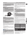 3
3
-
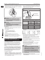 4
4
-
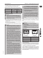 5
5
-
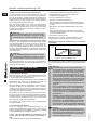 6
6
-
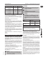 7
7
-
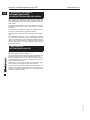 8
8
-
 9
9
-
 10
10
-
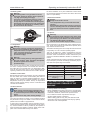 11
11
-
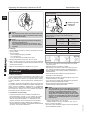 12
12
-
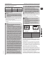 13
13
-
 14
14
-
 15
15
-
 16
16
-
 17
17
-
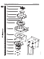 18
18
-
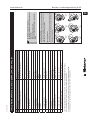 19
19
-
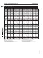 20
20
-
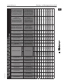 21
21
-
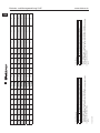 22
22
-
 23
23
-
 24
24


Elektror S-HP 265/33 Operating And Assembly Instructions Manual
- Category
- Measuring & layout tools
- Type
- Operating And Assembly Instructions Manual
- This manual is also suitable for
Ask a question and I''ll find the answer in the document
Finding information in a document is now easier with AI
in other languages
- Deutsch: Elektror S-HP 265/33
Other documents
-
HEYLO K 120 User manual
-
ABB DMP 180-4S Operating And Maintenance Instructions Manual
-
Maico EDR 31 Mounting And Operating Instructions
-
Maico DZF E Series Mounting And Operating Instructions
-
Marantec CS 310 FU Owner's manual
-
Schneider Electric ALTIVAR 18 User manual
-
Maico EZQ D Series User manual
-
HELIOS RDD Operating
-
Lenze 8200 motec Operating Instructions Manual
-
WEG MAS Getriebemotoren - Montageanleitung / Geared Motors - Mounting User manual