
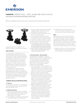
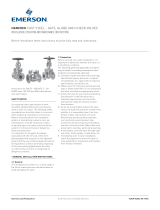
OPERATION AND MAINTENANCE MANUAL 12-2016
Operation and maintenance
manual for
PN25
DRIVE-READY
FLANGED
GATE VALVES
WITH SOFT SEALS
P/N
2911
2902
Approved for use by
President of Factory, JAFAR S.A.
Failure to comply with the guidelines and instructions in this Operation and
Maintenance Manual releases the manufacturer from all obligations, liability and guarantee.
Due to continuous business development, we reserve the right to introduce
modifications and structural changes to the presented product.

OPERATION AND MAINTENANCE MANUAL 12-2016
2
CONTENTS
1 TECHNICAL DESCRIPTION ............................................................................................................................ 3
1.1 PRODUCT DESIGNATION AND IDENTIFICATION .............................................................................. 3
1.2 USE ............................................................................................................................................................... 3
1.3 TECHNICAL SPECIFICATION .................................................................................................................. 3
2.1 DESCRIPTION OF THE VALVE DESIGN ................................................................................................ 3
2.2 MATERIALS ................................................................................................................................................ 4
2.3 DIMENSIONS .............................................................................................................................................. 5
2.4 REFERENCE STANDARDS ....................................................................................................................... 6
2.5 ORDERING INFORMATION ..................................................................................................................... 6
2.6 PRODUCTION AND ACCEPTANCE ........................................................................................................ 6
2.7 MARKINGS ................................................................................................................................................. 7
3 PROTECTION, STORAGE & TRANSPORT .................................................................................................... 7
3.1 PROTECTIVE COATINGS ......................................................................................................................... 7
3.2 PACKAGING ............................................................................................................................................... 7
3.3 STORAGE .................................................................................................................................................... 7
3.4 TRANSPORT ............................................................................................................................................... 8
4 ASSEMBLY AND INSTALLATION ................................................................................................................. 8
4.1 ASSEMBLY GUIDELINES ......................................................................................................................... 8
4.2 ASSEMBLY INSTRUCTIONS .................................................................................................................... 8
4.3 OPERATION ................................................................................................................................................ 9
4.4 GENERAL .................................................................................................................................................... 9
4.5 OCCUPATIONAL HEALTH AND SAFETY ............................................................................................. 9
5 WARRANTY TERMS AND CONDITIONS .................................................................................................... 10

OPERATION AND MAINTENANCE MANUAL 12-2016
3
1 TECHNICAL DESCRIPTION
1.1 PRODUCT DESIGNATION AND IDENTIFICATION
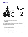
The subject of this Operation and Maintenance Manual is:
Type 2902 and 2911 drive-ready flanged cast iron wedge gate valves with soft seals.
- full smooth walled bore design
- wedge (closure) embedded in 100% pure elastomer
- non-rising spindle
- stem head-type seal in valve cover (O-rings)
1.2 USE
The gate valves with soft seals are intended for water supply systems, especially for potable water,
sewage systems, and industrial processing systems. The valves are intended for surface and underground
systems and must be installed in horizontal pipelines.
1.3 TECHNICAL SPECIFICATION
The Type 2902 and 2911 drive-ready flanged cast iron wedge gate valves with soft seals are applied in
transfer of potable water, process water and other liquids as approved by the manufacturer.
- Operating temperature range: +70°C max.
- Nominal diameter (dimension) range: DN40 to DN500 [mm]
- Maximum medium flow rate: - liquid: max. 4 [m/s]
- gas: max. 30 [m/s]
- The driving torque at opening start and closing end is as listed below:
- Valve control mode: the standard version of gate valve has the clockwise closing sense of rotation.
The closing sense of rotation can be opposite on special order.
- The valve connection flange design is acc. to EN 1092-2
with the sizes compliant with the nominal pressure values.
- the connection flanges are manufactured to EN ISO 2285210
- Valve drive coupling type: B3
- Installation length: EN 558-1 series 14 - Type 2911
series 15 - Type 2902
- Nominal pressure ratings (PN): - 2.5 MPa
2 DESIGN
2.1 DESCRIPTION OF THE VALVE DESIGN
Type 2902 and 2911 drive-ready flanged gate valves with soft seals manufactured by F.A. „JAFAR”S.A.
feature a smooth walled bore, a non-ring spindle, and an o-ring spindle seal installed in a head-type valve cover.
The stem is guided by a bushing in the valve cover neck and a sealing plug. The spindle seal is effected by the
plug sealing assembly, which is a system of o-rings. The gate valve closure is a cast iron wedge completely
coated with rubber and featuring a stem nut located on the wedge lug. The stem is equipped with an interlocking
collar installed by necking. From the bottom the stem collar rests on a seat in the head via a bushing which acts as
a sealed bearing. The plug over the flange is secured against loosening with a wire spring ring. The valve cover to
body joints is made with hex cap screws mounted flush with the valve cover and preserved with a paraffin
compound. The valve cover to body seal is a rubber gasket which also seals the bolt penetration points to prevent
any leaks from their leads. All inner and outer cast-iron surfaces of the valve are epoxy powder coated. The gate
valves from DN350 to DN600 feature a wedge guide system made of plastic inserts.
DN [mm] 40 50 65 80 100
125 150 200 250 300 350 400 450 500
Mmax [Nm]
25 50 100 200 250 280 300 320

OPERATION AND MAINTENANCE MANUAL 12-2016
4
The stem is tipped with a Form B3 (coupling type) key shaft sized according to EN ISO 5210.
2.2 MATERIALS
The table below lists the structural materials of the gate valves with soft seals.
Item Part designation Material Reference standard
1 Body Cast-iron, EN-GJS-400-15
or EN-GJS-500-7 EN 1563
2 Cover Cast-iron, EN-GJS-400-15
or EN-GJS-500-7 EN 1563
3 Sealing plug Brass EN 1982
4 Safety ring Steel grade 1.1260 74/H-84032
5 Wedge+skid
Cast-iron, EN-GJS-400-15
or EN-GJS-500-7
Rubber EPDM/NBR
Polyamide
EN 1563
EN 1563
ISO 1629
EN ISO 1874-1
6 Spindle nut Brass
or EN-GJS-400-15 EN 1982
EN 1563
7 Spindle Steel grade 1.4021 EN 10088-1
8 Valve cover gasket Rubber EPDM/NBR ISO 1629
9
10 O-ring Rubber EPDM/NBR ISO 1629
11 Bolt Steel, Fe/Zn5, stainless steel EN ISO 4762

OPERATION AND MAINTENANCE MANUAL 12-2016
5
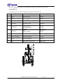
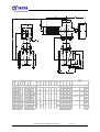
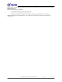
2.3 DIMENSIONS
-
40 140 240 150 84 110 188 238 461 170 11
50 150 250 165 99 125 198 248 471 170 13,5
65 170 270 185 118 145 232 283 507 170 14
80 180 280 200 132 160 255 307 530 170 17
100 190 300 235 156 190 23 290 346 565 170 21
125 200 325 19 270 184 220 329 385 604 170 26
150 210 350 20 300 211 250 400 457 675 170 26
200 230 400 22 360 274 310 475 538 750 170 34,5
250 250 450 25 425 330 370 560 625 875 180 42,5
300 270 500 28 485 389 430 635 700 950 180 51
350 290 550 30 555 448 490 34 720 785 1033 180 60
400 310 600 32 620 503 550 980 1060 1268 180 58
450 330 - 35 670 548 600 1050 1130 1340 180 65
500 350 700 37 730 609 660 1160 1240 1555 180 63
d
3
d
5
d
6
4
20
385
332
175 140
31
19
3
AUMA
type-flange / opening torque / No. of
turns
Saxx.x-Fx / [Nm] / ---
C
1
C
2
H
3
d
4
x
nd
1
[mm]
DN
2911
L
2902
L
C f D
[mm]
H
20
70
H
2
102
90
282 125
H
1
200
16
19
12
265 250
256
28
325
9x4 105
30 18x4 153
400
315
160
11x4 125
SA 7.6-F10
SA 14.2-F14 100-250
dd
2
37
4
8
20-60
SA 10.2-F10
SA 14.6-F14 300-500
K I n
40-120
SA 7.2-F7 10-30

OPERATION AND MAINTENANCE MANUAL 12-2016
6
2.4 REFERENCE STANDARDS
EN 1074-1 Valves for water supply. Fitness for purpose requirements and appropriate
verification tests. General requirements
EN 1074-2 Valves for water supply. Fitness for purpose requirements and appropriate
verification tests. Isolating valves.
89/H-02650 Valves and pipelines. Pressure and temperature ratings.
EN 1092-2 Flanges and their joints. Circular flanges for pipes,
valves, fittings and accessories, PN designated. Cast iron flanges.
EN19 Industrial valves. Marking of metallic valves
EN 12266-1 Industrial valves. Testing of metallic valves. Pressure tests, test procedures
and acceptance criteria. Mandatory requirements.
EN 558 Industrial valves. Face-to-face and centre-to-face dimensions of metal valves
for use in flanged pipe systems. PN-designated valves.
EN ISO 5210 Industrial valves. Multi-turn valve actuator attachments.
EN ISO 6708 Pipework components. Definition and selection of DN (nominal size).
EN 1559-1 Founding. Technical conditions of delivery. General.
EN 1561 Founding. Grey cast irons.
EN 1563 Founding. Spheroidal graphite cast irons.
EN 1370 Founding. Surface roughness inspection by
visual tactile comparators.
EN 10088-1 Stainless steels. List of stainless steels.
74/H-84032 Spring steel. Grades.
EN 1982 Copper and copper alloys. Ingots and castings.
EN 12420 Copper and copper alloys. Forgings.
ISO 965-1 General purpose ISO metric threads. Tolerances. Principles and basic data.
ISO 2903 Trapezoid ISO metric threads. Tolerances.
EN ISO 4762 Hexagon socket head cap screws.
EN 10204 Metallic products. Types of inspection documents.
ISO 1629 Rubbers and latices. Nomenclature.
EN ISO 1873-1 Plastics. Polypropylene (PP) moulding and extrusion materials. Designation
system and basis for specifications.
EN ISO 1874-1 Plastics. Polyamide (PA) moulding and extrusion materials. Designation
system and basis for specification.
EN ISO 12944-5 Paints and varnishes. Corrosion protection of steel structures by protective
paint systems. Protective painting systems.
2.5 ORDERING INFORMATION
Water supply system fittings are specific purpose industrial fittings, therefore orders must include:
- part number (P/N, equal to the product type);
- intended use, e.g. for water supply systems,
and:
- nominal diameter, acc. to EN ISO 6708
- nominal pressure, acc. to 89/H-02650;
- type of body material — acc. to EN 1561 or EN 1563
- maximum operating temperature, acc. to 89/H-02650.
2.6 PRODUCTION AND ACCEPTANCE
Type 2902 and 2911 drive-ready flanged gate valves with soft seals are accepted and produced in
accordance with EN 1074-2 (Valves for water supply. Fitness for purpose requirements and appropriate
verification tests. Isolating valves) and EN 12266-1 (Industrial valves. Testing of valves). All gate valves are leak
tested (100%). The tests include external body tightness and closing tightness.

OPERATION AND MAINTENANCE MANUAL 12-2016
7
2.7 MARKINGS
The gate valve marking meets the following standards: EN-19, EN-1074-1.
The valve bodies feature markings on the front and back walls of the body chamber. The marking
contains the following data:
- valve type (defined by the product reference standard number)
- nominal diameter
- nominal pressure
- body material type
- manufacturer trademark
The location on the valve specified in the documentation features the nameplate which contains the
following data: - manufacturer's company name and logo
- serial number
- sealing temperature rating
- construction mark "B" and/or mark "CE" (as applicable)
- product type.
3 PROTECTION, STORAGE & TRANSPORT
3.1 PROTECTIVE COATINGS
All inner and outer cast-iron surfaces are protected with electro-deposited epoxy coat. The coat has been
approved for contact with foodstuffs.
The anti-corrosion coating layer minimum thickness is 250µm.
The casting surface is pre-treated for epoxy coating in accordance with the relevant technical documentation and
EN ISO 12944-5.
The screws connecting the body and the cover are manufactured as stainless, grade OH18N9 or Fe/Zn5
(galvanised steel).
3.2 PACKAGING
The gate valves are packed on EURO pallets (1200x800) and protected with heat-shrunk film.
3.3 STORAGE
Store the gate valves in sheltered rooms.

OPERATION AND MAINTENANCE MANUAL 12-2016
8
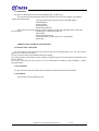
3.4 TRANSPORT
Transport the gate valves on sheltered vehicles.
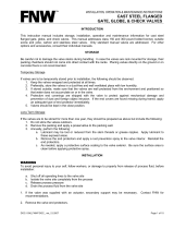
Heavy gate valves (DN350 and larger) shall be handled with the integrated handling pieces made of eye
bolts; the gate valves from DN40 to DN300 shall be handled on slings (see the example diagram below) and
secured from turning.
Never suspend the valve by its drive actuator when handling.
DN350>
DN40 to DN300
4 ASSEMBLY AND INSTALLATION
4.1 ASSEMBLY GUIDELINES
The TYPE 2902 and TYPE 2911 drive-ready flanged gate valves with soft seals can be installed in
underground or surface pipelines both in horizontal or vertical orientation. The listed products are suitable for
joining with the flanged ends of pipelines with the size equal to that of the valve flanges. Note that the system
must not expose the (gate) valve to bending or tensile stress from loading with the weight of unsupported pipeline
sections. It is recommended to perform installation works considering pipeline compensation due to temperature
and pressure. The valve assembled and adjusted by the manufacturer is ready for installation. Any dismantling of
the valve components may result in loss of seal.
When installing the gate valve with its drive actuator, follow the OHS requirements specified in the actuator
operation and maintenance manuals.
4.2 ASSEMBLY INSTRUCTIONS
Before attempting to install the valve, check the technical and commercial documents delivered with the
product to verify that the media and pipeline operating parameters comply with the manufacturer's declaration.
Any change in the operating conditions must be consulted with the valve manufacturer beforehand.
Before attempting to assemble the valve, remove the main bore plugs, check the inner surfaces of the
valve and thoroughly flush with water, if necessary.
CAUTION! If the product is damaged mechanically, do not install it in the pipeline.
Before commissioning the valve with the drive actuator and during the connection and adjustment of the
drive unit, verify the electric connections and fire protection according to the technical manual from the
drive actuator manufacturer.

OPERATION AND MAINTENANCE MANUAL 12-2016
9
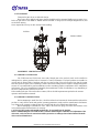
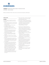
The figure below shows the method for coupling the gate valve with its drive actuator and the valve
orientation diagrams:
1. Valve; 2. Nut; 3. Gasket; 4. Pipeline flange; 5. Washer; 6. Fastening bolt
4.3 OPERATION
The gate valve shall be operated according to all relevant requirements for cut-off valves, i.e. either in fully
open or fully closed positions. Leaving the gate valve partially opened (or closed) may result in seal failure. To
ensure full performance, switch the gate valve periodically (once a year, from fully open to fully closed).
Overruning the valve operating limits may damage the valve
and the manufacturer's suretyship liability shall not apply.
4.4 GENERAL
This Manual applies to all Group 2000 products designed for equipping with actuators (i.e. gate valves of
various connection end types) and manufactured by FA. JAFAR S.A.:
- Cast iron flanged wedge gate valves with soft seals
- Gate valves with soft seals with threaded connection ends
- Gate valves with soft seals and ferrule connection ends
- Cast iron flanged wedge gate valves with soft seals for natural gas systems
- Cast iron annular wedge gate valves
4.5 OCCUPATIONAL HEALTH AND SAFETY
The valves are eligible for the OHS guidelines and recommendation concerning installation of pipelines
and devices for water supply stations, heat power plants, water treatment plants, sewage treatment plants,
pumping stations and other facilities, and eligible for the Polish Regulation concerning general OHS laws (use of
Recommended Permitted
Not permitted

OPERATION AND MAINTENANCE MANUAL 12-2016
10
personal protective equipment for hands, legs and head, and safety garment), especially at work with low or high
temperature hazard.
Misuse of this product is prohibited.
5 WARRANTY TERMS AND CONDITIONS
The product assembled, installed and operated in compliance with this Manual is covered by a
commercial warranty from the manufacturer. The conditions and period of the warranty is specified in the
warranty sheet.
-
 1
1
-
 2
2
-
 3
3
-
 4
4
-
 5
5
-
 6
6
-
 7
7
-
 8
8
-
 9
9
-
 10
10


Jafar 2911 Operation and Maintenance Manual
- Type
- Operation and Maintenance Manual
- This manual is also suitable for
Ask a question and I''ll find the answer in the document
Finding information in a document is now easier with AI
Related papers

Other documents
-
ITT Controls GH-500 Owner's manual
-
American Flow Control 2608ARAFMM Installation guide
-
NIBCO NHA300F Installation guide
-
 FNW 561 Installation guide
-
Sempell Pressure seal Gate Valve - Style A User guide
-
Apollo Conbraco 6GA21HB1LFA Installation guide
-
Watts FPP User guide
-
 Fasani Gate Valves Owner's manual
-
 Hancock Forged Steel Gate, Globe and Check Valves IOM Owner's manual
-
 Hancock Cast Steel Gate, Globe and Check Valves IOM Owner's manual


