Montigo C34-DV Owner's manual
- Category
- Fireplaces
- Type
- Owner's manual
This manual is also suitable for

www.montigo.com
Installation Operation & Maintenance Manual
Check local codes and read all instructions prior to installation.
XG0170 Canadian Heating Products Inc. Langley, BC V4W 4A Montigo Del Ray Corp. Ferndale, WA 98248 080610
C34DV Indoor
C38DV Indoor
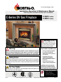
C-Series DV Gas Fireplace
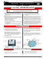
C38DV Indoor Shown
For Your Safety:
Do not store or use gasoline or other ammable vapors and liquids in the
vicinity of this or any other appliance.
Safety Notice:
Glass doors on gas replaces are extremely hot while the replace is on and remain
hot even after the replace has been turned off. Safety screens are available and
can reduce the risks of severe burns. Please keep children away from the replace
at all times.
®
C US
Warning:
Improper installation, adjustment, alteration, service or maintenance can cause
injury or property damage. Refer to this manual. For assistance or additional
information consult a qualied installer, service agency or the gas supplier.
• Installer: Leave this manual
with the appliance.
• Consumer: Retain this
manual for future reference.
• Do not try to light any appliance.
• Do not touch any electrical
switch; do not use any phone in
your building.
• Immediately call your gas
supplier from a neighbor's
phone. Follow the gas supplier's
instructions.
• If you cannot reach your gas
supplier, call the re department.
Installation and service must be
performed by a qualied installer,
service agency or the gas supplier.
Warning: If the infor-
mation in these instructions is not
followed exactly, a re or explosion
may result causing property dam-
age, personal injury or death.
WHAT TO DO IF YOU SMELL GAS

Page 2
C-Series DV Gas Fireplace
Part No. XG0170 - 080610
Warning:
Read this manual before installing, operating or troubleshooting this
appliance. Please retain this owner's manual for future reference.
Congratulations!
Congratulations on selecting a Montigo gas replace, an elagent
and well designed gas replace built to your specications. The
Montigo gas replace you have selected is designed to provide
the utmost in safety, reliability, and engineering standards.
As the owner of this new replace, you'll want to read and care-
fully follow all the instructions contained in this Installation,
Operations and Maintenance manual. Pay special attention to all
cautions, warnings, and Important warnings.
This owner's manual should be retained for future reference. We
suggest that you keep it with all your other important documents
and product manuals.
The information contained in this owner's manual, unless noted
otherwise, applies to all models, and gas control systems.
Your new Montigo gas replace will give you years of durable,
reliable use. Welcome to the Montigo family of gas replace
products.
Table Of Contents
Safety Alert Key:
• DANGER! Indicates a hazardous situation which, if not avoided will result in death or serious injury.
• WARNING! Indicates a hazardous situation which, if not avoided could result in death or serious injury.
• CAUTION! Indicates a hazardous situation which, if not avoided, could result in minor or moderate injury.
• NOTICE: Used to address practices not related to personal injury.
• Important: Used to address practices not related to personal injury.
Congratulations
Safety Alert Key
Introduction .............................................................................. 3
Installation
Installing and Framing the Fireplace .............................. 4
Installing the Gasline ...................................................... 5
The Remote Switch ........................................................ 6
Direct Vent Installation ................................................... 5
General Venting Requirements ......................... 5
Terminations ...................................................... 6
Top Vent Venting Runs ................................7 - 9
Rear Vent Venting Runs ........................... 10 - 11
Finishing around the replace
Facing .............................................................. 12
Mantels and Surrounds ................................... 12
Wiring ..................................................................13 - 14
Installing Optional Fans................................................ 13
Removing and Installing the Door ................................ 15
Installing the Horizontal Trim ........................................ 15
Positioning the Logset .................................................. 16
Operation ..................................................................17 - 20
Maintenance ....................................................................20 - 22
Spare Parts ................................................................. 22
Warranty ................................................................................. 23
Appendix
A. Termination Locations .............................................. 24
B State of Massachusetts / Amendment .................... 25
Notes ..................................................................................... 26

Page 3
C-Series DV Gas Fireplace
Part No. XG0170 - 080610
Introduction
Thank You for choosing a Montigo Gas Fireplace.
About this Fireplace:
The C-Series DV is a dual burner replace with glowing embers and
ve piece ceramic bre logset. The replace is available in two models,
and in top or rear vent for each model.
Standard Log Set
The C34DV is rated for Natural Gas at 20,000 BTU/H (5.86
Kilowatts) Input or Propane at 20,000 BTU/H (5.86 Kilowatts) Input.
QC34DT; Top Vent, Millivolt Pilot.
QC34DR; Rear Vent, Millivolt Pilot.
QC34DT-I; Top Vent, Intermittent Pilot (HSI).
QC34DR-I; Rear Vent, Intermittent Pilot (HSI).
QC34DT-F; Top Vent, Electronic Ignition (IPI).
QC34DR-F; Rear Vent, Electronic Ignition (IPI).
Standard Log Set
The C38DV is rated for Natural Gas at 25,000 BTU/H (7.32
Kilowatts) Input or Propane at 25,000 BTU/H (7.32 Kilowatts) Input.
QC38DT; Top Vent, Millivolt Pilot.
QC38DR; Rear Vent, Millivolt Pilot.
QC38DT-I; Top Vent, Intermittent Pilot (HSI).
QC38DR-I; Rear Vent, Intermittent Pilot (HSI).
QC38DT-F; Top Vent, Electronic Ignition (IPI).
QC38DR-F; Rear Vent, Electronic Ignition (IPI).
How to use this manual:
This manual covers installation, operation and maintenance. Lighting,
operation and care of this replace can be easily performed by the
homeowner. However, all installation and service work should be
performed by a qualied or licensed installer, plumber, or gastter who
is qualied or licensed by the state, province, region, or governing body
in which the appliance is being installed.
This manual covers all models and unless otherwise specied, the
designation C-Series DV refers to all models. Sections which are
specic to a particular model are marked with a symbol, plus the
appropriate model number.
CAUTION!
Due to its high operating temperatures, the appliance should
be located out of traffic & away from furniture and draperies.
Children and adults should be alerted to the hazards
of the high surface temperature, which could cause
burns or clothing ignition.
Young children should be carefully supervised when
they are in the same room as the appliance.
Clothing or other flammable materials should not be
placed on or near the appliance.
Warranty and Installation Information:
The Montigo warranty will be voided by, and Montigo disclaims any
responsibility for, the following actions:
QModication of the replace and/or components including Direct-
Vent assembly or glass doors.
QUse of any component part not manufactured or approved by
Montigo in combination with this Montigo replace system.
QInstallation other than as instructed in this manual.
Consult your local Gas Inspection Branch on installation requirements
for factory-built gas replaces. Installation & repairs should be done by
a qualied contractor.
Installations in Canada must conform to the current CAN/CGA B-149.1
and .2 Gas Installation Code and local regulations. If the optional air-
circulating fan kit is installed, it must be electrically grounded in accordance
with CSA C22.1 Canadian Electrical Code Part 1 and/or Local Codes.
Installations in the USA must conform to local codes, or in the absence
of local codes to the National Fuel Gas Code, ANSI Z223.1-1988. If the
optional air-circulating fan is installed, it must be grounded in accordance
with local codes or, in the absence of local codes, with the National
Electrical Code, ANSI/NFPA 70-1987. See Appendix B for installation
within the State of Massachusetts.accordance with local codes or, in
the absence of local codes, with the National Electrical Code, ANSI/
NFPA 70-1987.
See Appendix B for installation within the State of Massachusetts.
WARNING
HOT GLASS WILL
CAUSE BURNS.
DO NOT TOUCH GLASS
UNTIL COOLED.
NEVER ALLOW CHILDREN
TO TOUCH GLASS.

Page 4
C-Series DV Gas Fireplace
Part No. XG0170 - 080610
Installation
Installing and Framing the Fireplace
The replace may be installed in any location that maintains proper clear-
ances to air conditioning ducts, electrical wiring and plumbing. Safety,
as well as efciency of operation, must be considered when selecting
the replace location. Try to select a location that does not interfere
with room trafc, has adequate ventilation, and offers an accessible
pathway for Direct Vent installation. Refer to page 4 - Vent Installation
for more information.
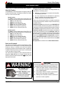
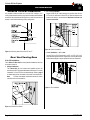
The replace dimensions are shown below:
When installing a shelf over the top of the replace, the following
guidelines must be adhered to: For Rear Vent applications the
minimum clearance from the top of the replace to a shelf is 6 1/2". For
Top Vent applications, the minimum clearance is 13 1/2". (Minimum
2" clearance must still be maintained around the vent pipes.)
Figure 4. Framing for shelves over the fireplace.
Top Vent
Figure 3. Minimum Corner framing dimensions, using a 45° elbow.
Figure 2. Framing dimensions.
* When sheetrock is
not used behind the
fireplace, framing
depth may be reduced
by 5/8"
Framing
Top View
Front View Side View
* Clearance from the top of the replace to a combustible ceiling
within the replace enclosure.
** Refer to graph and requirements on Page 11.
Unprotected combustible walls which are perpendicular to the replace
opening, must not project beyond the shaded area shown in Figure 25.
For protection against freezing temperatures, it is recommended that
outer walls of the chase be insulated with a vapor barrier. This will reduce
the possibility of a cold-air convection current on the replace.
Figure 1. Fireplace dimensions.
Rear Vent (On Applicable Models)
M
N
O
N
P
Q
2" clearance
to corners only
M
N
O
N
P
Q
2" clearance
to corners only
M
N
O
N
P
Q
2" clearance
to corners only
M
N
O
N
P
Q
2" clearance
to corners only
M
N
O
N
P
Q
2" clearance
to corners only
WARNING!
When this appliance is installed directly on any combustible mate-
rial other than wood ooring, it must be installed on a metal or
wood panel extending the full width and depth of the appliance.
MT
6 1/2
S
13 1/2
Framing / Header,
shelf
L
M
MEL Short
90 elbow
shelf
Framing/ Header
Clearances
These clearances apply to all dimensions except the framed opening,
where the clearance to combustibles is 0". The C-Series DV clearances
to combustible materials are:
M N O P Q R T
C34-DV 363
/
433 141
/
250 353
/
8303
/
8397
/
8
C38-DV 393
/
437 175
/
856 395
/
8333
/
8427
/
8
C42-DV 44 411
/
418 613
/
8433
/
8375
/
8471
/
8
C34-DV C38-DV
Top - Rear Vent * 6 1/2" 6 1/2"
Top - Top Vent 13 1/2" 13 1/2"
Back 0" 1"
Sides 1" 0"
Floor 0" 0"
Mantle** 6" 8"
C34-DV 333
/
4311
/
231 11
/
418 1 3
/
4213
/
48 5 8 251
/
4
C38-DV 373
/
4341
/
2343
/
411
/
421 1 7
/
8241
/
89 5 8 283
/
8
C42-DV 42 383
/
4383
/
411
/
4241
/
211 63
/
4277
/
8101
/
458 321
/
2
A B C D E F G H I J K L
11
15

Page 5
C-Series DV Gas Fireplace
Part No. XG0170 - 080610
Installation
Q All joints must be secured with a minimum of two screws per joint
Q Vent terminations must not be recessed in walls or siding
Q Horizontal runs must be supported by a minimum of two supports per horizontal
run. A minimum of one screw on each side of support is also required
Q Flex vent sections may be stretched up to 50% of their total length (eg. a
24" section may be stretched to 36")
Q Maximum horizontal run for a flex section with no vertical rise is 3 feet.
Q Flex vent sections over 3 feet must fall within the limits set by the venting
graph and must have a minimum vertical rise of 3 inches per foot of flex.
Q Solid vent sections may be cut less than half way from the female end
Q Venting components can be used in any combination of solid/rigid pipe or
flex pipe and in any orientation (Male connectors can face in any direction)
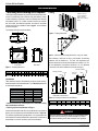
Vent Terminations
Selecting A Termination Location
Choosing your vent termination location will help to determine whether
you need to use a top vent or rear vent replace. Figure 6, below, shows
typical replace locations and the venting options they provide.
For a more detailed diagram of allowed termination locations, see Ap-
pendix A.
Figure 6. Fireplace locations and vent terminations.
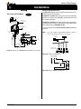
Installing The Gas Line
The gas line must be installed before nishing the C-Series DV Fireplace.
Natural Gas requires a minimum inlet gas supply pressure of 5.5" W.C.
& a manifold pressure of 3.5" W.C. Propane Gas requires a minimum
inlet gas supply pressure of 11" W.C. & a manifold pressure of 10" W.C.
Provision must also be made for a 1/8" N.P.T. plugged tapping and be
accessible for test gauge connection immediately upstream of the gas
supply controls to the appliance. The replace gas connection and the
main operating gas valve is located behind the removable trim at the
bottom of the unit and need only be attached to the gas line with an
approved tting, as required by the applicable installation codes.
• Only use gas shut-off valves approved for use by the state, province,
region, or governing body, in which the appliance is being installed, or
as required by the applicable installation codes.
• Flexible gas connectors must not exceed 3 feet in length, unless it is
allowable within applicable installation codes.
Note: After gas line is connected, each appliance connection,
valve and valve train must be checked while under normal
operating pressure with either a liquid solution, or leak
detection device, to locate any source of leak. Tighten
any areas where bubbling appears or leak is detected until
bubbling stops completely or leak is no longer detected.
DO NOT use a flame of any kind to test for leaks.
Figure 5. Gas line access.
The appliance and its individual shut-off valve must be disconnected
from the gas supply piping system during any pressure testing of that
system at test pressures in excess of 1/2 psig (3.5 kPa).
The appliance must be isolated from the gas supply piping system by
closing its individual manual shut-off valve during any pressure testing
of the gas supply piping system at test pressures equal to or less than
1/2 psig (3.5 kPa).
Vent Installation
This section covers the installation of direct venting and terminations.
Installation Requirements
Q
C-Series DV fireplaces are certified for use with Montigo Premium Series
(5"/8") venting components. The C-Series DV Top Vent may be used with
the Montigo Standard Series (4"/7") components on vertical vent runs only.
Q Minimum 1" clearance to combustibles around the vent pipe.
Q Use only certified Montigo vent components. (Use of other parts will void
the Montigo warranty, and may impede the operation of the fireplace.)
CAUTIONS!
Vent terminations can be very hot. If the termination is less than 7 feet
above a public walkway, it should be tted with a certied Montigo
Heat Guard. (Part no. PTKOG).
Do not obstruct, or attempt to conceal the vent termination.
These actions will affect the operation of the replace, and may
be hazardous.
In heavy snow areas, take extra care to prevent snow buildup
from obstructing the vent termination.
Use Montigo Vinyl Heat Shield (Part no. VSS) when using on
applications with vinyl siding to guard against possible damage.

Page 6
C-Series DV Gas Fireplace
Part No. XG0170 - 080610
Installation
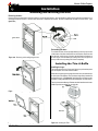
Installing Terminations with Built-In Frames
Installing Terminations with MSR Frames
12
12
1. Frame the termination opening to 12" x 12".
2. Fasten the termination to the studs using a minimum of 4 screws.
11
11
1. Frame the termination opening to 11" x 11".
2. Fasten the termination to the studs using a minimum of 4
screws.
Installing Terminations with MOSR Frames
1212
12
MOSR
1. Frame the termination opening to 12" x 12".
2. Fasten the MOSR frame to the interior side of the studs using a
minimum of 4 screws.
3. Insert the termination into the MOSR frame as shown here, and
attach by screwing through the four pilot holes in the termination.
MSR
MTO-3 (4"/7")
PTO-3 (5"/8")
MTO-3F (4"/7")
PTO-3F (5"/8")
MTO-3 (4"/7")
PTO-3 (5"/8")
MTKOG (4"/7")
PTKOG (5"/8")
1. Ensure that the two long mounting brackets are facing the bottom
of the termination. (See inset). This will provide more heat protection
at the top of the termination, where temperatures are highest.
2. Attach to the faceplate of the termination using four sheet metal
screws.
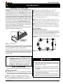
Installing Heat Guards over Terminations
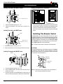
Installing The Remote Switch
The C-Series DV's gas valve, located behind the lower trim, may be
connected to a wall switch. The valve will either generates its own power
on a millivolt circuit or draws its power from an AC connection inside
the replace, depending on the model of your unit. Use only low voltage
wire, and DO NOT connect any external power to the remote switch.
Refer to Figures 26 & 27 for wiring requirements.
Note: The switch location must not exceed 30' from the replace.
Heat Shields
Due to high ue temperatures, heat shields are required on all C Series
DV installations (except those with vertical terminations) at the point
where the venting connects to the termination. With the heat shield,
vent clearances can be maintained at 1”.
Figure 8. Heat Shield. Install by sliding over the vent pipe where it
passes through combustible construction.
1 MIN
1 MIN
1 MIN. Both
sides Typical
RHS8 Heat
Shield

Page 7
C-Series DV Gas Fireplace
Part No. XG0170 - 080610
Installation
Top Vent Venting Runs
For the C-Series DV Top Vent, there are two types of installations:
A) Through-The-Wall Installations and B) Vertical (Through-The-Roof)
Installations.
A) Through-The-Wall Installations
Before you install any venting, you must determine whether the venting
run will be acceptable. Unacceptable venting can affect the replace's
combustion.
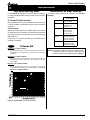
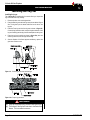
The Venting Graph
Measure the vertical height from the replace hearth to the centre of
the termination and the horizontal run from the from the replace ue
collar to the wall ange of the termination. Plot on the Venting Graph
(Fig. 9) with an 'X'.
If the 'X' falls on or above the top boundary of the shaded area, the
installation is acceptable.
C-Series DV
Example A: (Acceptable Installation)
If the vertical dimension from the hearth is 84" and the horizontal run to
the wall flange of the vent termination is 30", this would be an acceptable
installation.
Example B: (Acceptable Installation)
If the vertical dimension from the hearth is 108" and the horizontal run to
the wall flange of the vent termination is 120", this would be an accept-
able installation.
Example C: (Unacceptable Installation)
If the vertical dimension from the floor of the fireplace is 72" and the
horizontal run to the wall flange of the vent termination is 84", this would
NOT be an acceptable installation.
Figure 9. C34-DV, C38-DV Top Vent Venting Graph
5" / 8" Venting
A - Termination PTO-3 (3" Length)
PTO-3F (3" Length)
B - Stucco Kits MSR (Stucco Frame)
MOSR (Stucco Can)
BSR ( Brick Can)
C - Flex Sections PFL-1 (12" Section)
PFL-2 (24" Section)
PFL-3 (36" Section)
PFL-4 (48" Section)
D - Rigid
Sections
PEXT-1 (12" m/f Section)
PEXT-2 (24" m/f Section)
PEXT-3 (36" m/f Section)
PEXT-4 (48" m/f Section)
E - Elbows PEL-90MM (m/m 90° Elbow)
PEL-90FF (f/f 90° Elbow)
PEL-90FM (f/m 90° Elbow)
NOTES: All dimension lengths for vertical or horizontal runs are
measured from centre of the vent pipe. Venting runs must
fall within the limits set by the venting graph (see Figure 9).
C-Series DV
B
A
18”
C
C38 42 7/8”
C34 39 7/8”
Installation of Rear Vent DV
The following venting components are available for the Rear Vent
installation:

Page 8
C-Series DV Gas Fireplace
Part No. XG0170 - 080610
PEL
Example 1:
For our shortest venting conguration use components A and E (see
table on page 6).
Figure 10. Typical Top Vent installation. If the 90° elbow is installed
directly on the fireplace, for height to the center of the
termination see chart on page 4.
Horizontal Venting
Figure 11. Typical Top Vent installation. The solid sections can be used in
various combinations to obtain the desired vent run. The vent
run must fall within the limits set by the venting graph.
90° Elbow
PEXT Section
Termination
Figure 12. Extended Installation using a combination of solid and flex
venting. Use the vent graph to determine your allowable
run, then select appropriate components.
Figure 13. Retracted Installation using a combination of solid and flex
venting. Use the vent graph to determine your allowable
run, then select appropriate components.
Figure 14. Horizontal flex installation with no vertical rise.
Installation
PEL-90F/F Elbow
Example 2:
Rigid sections and an elbow used in conjunction with 3 ft. ex section
(MFL-3) will, when extended in a ve foot chase, allow for a maximum
horizontal run of twelve and one-half feet from the centre of the replace
to outside wall and a minimum of 7'6" when retracted in opposite direction
(see Figure 12 & 13).
"C" ex sections and "D" rigid sections may be used in conjunction with
one another to obtain different possible horizontal length installations,
Figure 13.
NOTE: Flex section with no vertical rise must not exceed maximum
horizontal length of 3 feet (see Figure 14). Flex runs over 3 feet must
fall within the limits set by the venting graph, and must have a minimum
vertical rise of 3" per foot of ex.
36” max.
Flex Section
Hearth
Termination
Exterior
Wall

Page 9
C-Series DV Gas Fireplace
Part No. XG0170 - 080610
Installation
B. Vertical (Through-The-Roof) Installations
Vertical rise > 12' can be reduced
Vertical Terminations must be installed:
• minimum 2' (two feet) above the highest point where vent
passes through the roof.
• minimum 6' (six feet) from a mechanical air inlet
• minimum 18" (1 1/2 feet) from a parapet wall.
Maximum vent height is 32 feet above replace.
Note: Flame characteristics will change if the maximum vent height
is used.
Minimum clearances 1" from vent to all combustible materials must
be maintained.
4" / 7" Venting 5" / 8" Venting
A - Termination MVTK-1 PVTK-1
B - Flex Sections MFL-1 (12" Section)
MFL-2 (24" Section)
MFL-3 (36" Section)
MFL-4 (48" Section)
PFL-1 (12" Section)
PFL-2 (24" Section)
PFL-3 (36" Section)
PFL-4 (48" Section)
C - Rigid Sections MEXT-1 (12" m/f Section)
MEXT-2 (24" m/f Section)
MEXT-3 (36" m/f Section)
MEXT-4 (48" m/f Section)
PEXT-1 (12" m/f Section)
PEXT-2 (24" m/f Section)
PEXT-3 (36" m/f Section)
PEXT-4 (48" m/f Section)
D - Support Ring
& Plate
MSPXT-8 PSPXT-8
E - Firestop FS-8 PS-8
F - Roof Flashing MRF-7 (1/12 - 7/12 pt.)
MRF-12 (7/12 - 12/12 pt.)
PRF-7 (1/12 - 7/12 pt.)
PRF-7 (7/12 - 12/12 pt.)
G - Adaptor / Vent
Reducer
PVA5487 (5"/8" to 4"/7")
A maximum of two offsets (each offset has two 90° bends) may be
made and shall not exceed total length of 25% of the vertical vent
height, when measured center to center of piping.
Example: Typical vent installation.
20' vertical vent
2 - 2' offsets required
25% of 20' = 5' max. offset allowed
This venting conguration meets requirements.
MEXT/PEXT
MEXT/PEXT
MXT-10/PXT-10
Figure 15. Straight, vertical venting showing required PXT-10 adaptor
(supplied with the PVTK-1 termination).
Figure 17. Vertical venting with 2 offsets (1 offset= two 90° bends).
Figure 16. Vertical venting with 1 offset (1 offset= two 90° bends).

Page 10
C-Series DV Gas Fireplace
Part No. XG0170 - 080610
Installation
Figure 20. Corner installation.
Figure 21. Flex installation.
2. 45° Corner Installation.
Attach an PEL-45 (45° elbow) directly onto the ue collar. Cut the
PXT-20 to suit, and attach it to the PEL-45. Slide the replace into
position and attach to the termination. Maximum horizontal run
must not exceed 20"
3. Corner Installation — 45° or less.
Use an PTO-3 or PTO-3F termination, an PFL-1 or PFL-2(12" or 24"
compressed length) and a frame, if appropriate. Flex may be turned to
obtain desired degree of angle required but must not exceed 45°.
Figure 19. Extended installation.
Rear Vent Venting Runs
A. No Lift Installations
The C-Series DV Rear Vent has three possible installations which do
not require vertical lift.
1. Straight Installation.
The C-Series DV rear vent versions are supplied with and 18"
extension pipe (PXT-20) with female/female connections. For shorter
installations, cut the PXT-20 to the desired length. Refer to page 4
for measurements from the hearth to the center of the termination.
Note: For Rear Vent models, maximum horizontal run with no
vertical lift must never exceed 20".
Figure 18. Reducing Vertical Vent from 5/8" to 4/7".
Reduced Vertical Installation
It is possible to reduce vertical vent runs from 5"/8" venting to 4"/7"
venting. Reduced vertical venting may only be used when the installation
exceeds 12 feet and terminates through the roof, and if the vertical vent
reducer is used with the following venting conguration.
PXT-20
PEL-45
PXT-20

Page 11
C-Series DV Gas Fireplace
Part No. XG0170 - 080610
Installation
Example A: (Acceptable Installation)
If the vertical dimension from the hearth is 84" and the horizontal
run to the wall ange of the vent termination is 30", this would be
an acceptable installation.
Example B: (Acceptable Installation)
If the vertical dimension from the hearth is 108" and the horizontal
run to the wall ange of the vent termination is 120", this would be
an acceptable installation.
Example C: (Unacceptable Installation)
If the vertical dimension from the oor of the replace is 60" and
the horizontal run to the wall ange of the vent termination is 108",
this would NOT be an acceptable installation.
B. Multi-Elbow Installations
For more difcult installation situations, the C-Series DR Rear Vent may
be installed with two - 90° elbows and up to 15' of horizontal run. If using
this installation option, you must adhere to the following guidelines:
Important: Some models are not available to be installed in a rear
vent application. Please refer to the model specications on page
2 of this manual.
the rst 90° elbow must be placed directly on the ue collar
you must have a minimum vertical lift of 50" (measured from the
hearth)
your vent run must fall within the limits set by Figure 22.
Before you install any venting, you must determine whether the venting
run will be acceptable. Unacceptable venting can affect the replace's
combustion.
The Venting Graph
Measure the vertical height from the replace hearth to the centre of
the termination and the horizontal run from the from the replace ue
collar to the wall ange of the termination. Plot on the Venting Graph
(Fig. 22) with an 'X'.
If the 'X' falls on or above the top boundary of the shaded area, the
installation is acceptable.
Figure 22. C-Series DV Multi-Elbow Venting Graph.
Figure 23. Multi-elbow installation. Distance 'H' must be a minimum of
of 50". The vent run must comply with figure 22.
NOTES: All dimension lengths for vertical or horizontal runs are
measured from center of the vent pipe.
Venting runs must fall within the limits set by the venting
graph (see Figure 22).
Installation Of Rear Vent DV
The following venting components are available for an C-Series DV in
a Rear Vent installation:
5" / 8" Venting
A - Termination PTO-3 (3" Length)
PTO-3F (3" Length)
B - Stucco Kits MSR (Stucco Frame)
BSR-4 (4" Brick Frame)
BSR-6 (6" Brick Frame)
MOSR (Stucco Can)
C - Flex Sections PFL-1 (12" Section)
PFL-2 (24" Section)
PFL-3 (36" Section)
PFL-4 (48" Section)
D - Rigid
Sections
PEXT-1 (12" m/f Section)
PXT-20 (20" section)
PEXT-2 (24" m/f Section)
PEXT-3 (36" m/f Section)
PEXT-4 (48" m/f Section)
E - Elbows PEL-90MM (m/m 90° Elbow)
PEL-90FF (f/f 90° Elbow)
PEL-90FM (f/m 90° Elbow)
PEL-45FM (f/m 45° Elbow)
18
B
A
18”
C
C34 25 1/4”
C38 28 3/8”

Page 12
C-Series DV Gas Fireplace
Part No. XG0170 - 080610
Installation
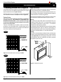
Finishing Around the Fireplace
Combustible mantels and mouldings may be safely installed over the
top and on the front of the replace provided that they do not project
beyond shaded area shown in Figure's 24 & 24a.
Side wall clearances are 3". Combustible surrounds may be installed
with 3" clearance to the side of the replace as shown in Figure 25.
Fireplace Facing
When selecting the nish material for your replace, it is important to
remember the following: THE HORIZONTAL LOUVRES MUST NOT
BE OBSTRUCTED IN ANY WAY - to do so restricts the air supply
for the control compartments and heat exchanger it also prevents
access for servicing controls.
The face of the replace may be painted to match the room decor,
provided you use a heat-resistant paint. Decorative facing must not
extend past the replace opening at all, because it will interfere with
the access to retainers for removal of glass door.
Mantels & Surrounds
NOTE: National Canadian Gas Association mantel test requirements
are for re hazard prevention to combustible materials.
New technology, to meet consumer and government demands for the
wise use of energy, has prompted us to manufacture many models of
replaces which are hot, fuel and energy efcient.
Please be aware; temperatures over the mantel will rise above normal
room temperature and walls above replace may be hot to touch.
Warning:
When covering the upper metal portion of the replace with a non-
combustible material Please Note: The decorative facing materials
may be subject to temperatures in excess of 250° F. This should be
considered when selecting facing materials.
We recommend careful consideration be given to the effects of elevated
mantel temperatures which may be in excess of product design, for
example: candles, plastic or pictures. This can cause melting, deformation,
discoloration or premature failure of T.V. and radio components.
Painting:
Special care is recommended by the Master Painters and Decorators
Association, when painting the replace surrounds, to select and apply
a quality Alkyd sealer prior to the applying of latex paints. This is to
prevent leaching of water from evaporation and causing a brownish
staining effect to paint over coats.
Figure 25. Combustible surrounds.
Figure 24. Combustible mantles and facings for C34DV.
Figure 24a. Combustible mantles and facings for C38DV.
C34DV
C38DV

Page 13
C-Series DV Gas Fireplace
Part No. XG0170 - 080610
Installation
Wiring
Gas Control and Pilot Wiring C-Series DV-I
Honeywell (Q3450)
Pilot Assembly
Pilot Electrical
Harness Connector
Honeywell Gas
Control (SV9501M)
Gas Control
Connector Fuse
Limit
Switch
Wall
Switch
Fan Plug
Receptacle
Junction Box
Junction Box Cover
White
Black
Green
40 VA
Transformer
115VAC
24VAC
Grnd Screw
Figure 26. Wiring for the C-Series DV-I with Honeywell gas control and pilot.
Wiring for the optional Fan Kit
All C-Series DV replaces may be equipped with optional fan kits for
circulating heat into the living space.
Installations in Canada which employ the fans must be electrically
grounded in accordance with CSA C22.1 Canadian Electrical Code
Part 1 and/or Local Codes.
Installations in the USA which employ the fans must be grounded in
accordance with local codes or, in the absence of local codes, with the
National Electrical Code, ANSI/NFPA 70-1987.
For more information see the Fan Kit Installation Guide included with
the fan kit.
NOTE: If any of the original wire supplied with the appliance is replaced, it
must be replaced with the same type, or its equivalent.
Figure 26b. Wiring schematic for optional fans.
Figure 26a. Wiring for optional fans.
115/1/60 Supply
G L1 L2
G
L2-WH
L1-BLK
Quick Connect
plug to motor

Page 14
C-Series DV Gas Fireplace
Part No. XG0170 - 080610
Figure 27. Wiring for the SIT IPI Wiring Schematic
Installation
Gas Control and Pilot Wiring C-Series DV-F
CAUTIONS!
QDO NOT OPERATE THIS FIREPLACE WITHOUT THE
GLASS DOOR OR WITH A BROKEN GLASS DOOR.

Page 15
C-Series DV Gas Fireplace
Part No. XG0170 - 080610
Installation
Removing and Installing the Door
Removing the door:
Remove the trim (as described in the next column) to access the door latches. Open the latches by pulling Part A upwards and towards you to
disengage Part B from the door. Lift Part B clear of the door. Repeat for both latches. Be sure to hold the door carefully so it does not fall. (See
gure 28a.)
Figure 28a. Removing and installing the glass door.
Figure 28b. Removing and installing the glass door.
Figure 28c. Removing and installing the glass door.
Re-installing the door:
To re-install the door, tilt the top edge towards you and line up the tabs
of the bottom of the door with the slots on the replace. Place the tabs
into the slots, and tilt the top of the door back towards the replace as
far as it will go. Close the latches by hooking Part B onto the groove at
the top of the door and pushing Part A down completely.
Installing the Trim & Bafe
Installing the Logs:
The 6 horizontal trim pieces (3 upper and 3 lower) are purchased separate
from the replace, and must be eld-installed.
Install the trim by placing the top edge of the trim over to the retainer clips
on either side of the replace. Push the bottom edge rmly inwards and
the trim will snap on. (See gure 29) Install the upper trim pieces so that
the bafe is resting between the top and middle piece, as shown below.
The trim piece with the Montigo Emblem should be installed on the lower
middle clips with the emblem on the right side.
Figure 29. Installing the Trims.

Page 16
C-Series DV Gas Fireplace
Part No. XG0170 - 080610
Installation
Installing the Log Set
Installing the Logs:
The C-Series DV is supplied with ve ceramic bre logs. Unpack the
logs and handle them very carefully.
1. Remove the door cover and the glass door.
2. Place the Back log onto the back log rest as shown below in gure
24a. The log has lip on the bottom which ts into the slot on the
log rest.
3. Place the Front log onto the front log rest as shown in gure 30.
Center the log from side to side, and push it against the back of the
log rest. Carefully push the log onto the metal spikes on the log rest.
4. Place the top logs in position as shown in gure 30a, place the
centre log down rst, then the right and left logs.
5. Start the replace. If the ame appears satisfactory, replace the
glass door and door cover.
CAUTIONS!
QIf logs are not placed properly, excessive sooting will result.
QThe surface of the logs will crack due to the heat of the
ames. This is a normal occurrence.
Figure 30. Positioning for the front and back logs.
Figure 30a. Proper log placement.

Page 17
C-Series DV Gas Fireplace
Part No. XG0170 - 080610
Operation - Model C-Series DV
C-Series DV
WARNING: If you do not follow these instructions exactly, a re or explosion may result causing
property damage, personal injury or loss of life.
Q If you cannot reach your gas supplier, call the Fire
Department.
C. Use only your hand to push in or turn the gas control knob.
Never use tools. If the knob will not push in or turn by hand,
don't try to repair it, call a qualified service technician. Force
or attempt to repair may result in a fire or explosion.
D. Do not use this appliance if any part has been under water.
Immediately call a qualified service technician to inspect the
appliance and to replace any part of the control system, and
any gas control which has been under water.
A. This appliance has a pilot which must be lighted by hand.
When lighting the pilot, follow these instructions exactly.
B. BEFORE LIGHTING smell all around the appliance area for
gas. Be sure to smell next to the floor because some gas is
heavier than air and will settle on the floor.
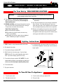
What To Do If You Smell Gas:
Q Do not try to light any appliance.
Q Do not touch any electrical switch; do not use any phone
in your building.
Q Immediately call your gas supplier from a neighbour's
phone. Follow the gas supplier's instructions.
To Turn Off Gas To Appliance:
3. Push in gas control knob slightly and turn clockwise to
"Off". Do not force.
4. Flip up the lower trim.
1. Turn off remote switch.
2. Flip down the lower trim.
1. STOP! Read the safety information above on this label.
2. Flip down the lower trims.
3. Push in gas control knob and turn clockwise to "OFF."
4. Wait five (5) minutes to clear out any gas. Smell for gas,
including near the floor. If you then smell gas, STOP! Follow
"B" in the safety information above on this label. If you don't
smell gas, go to the next step.
5. Locate pilot burner (See illustration at right.) and follow steps
below.
6. Turn knob on gas control counter clockwise to
"PILOT."
7. Push in gas control knob completely and hold. Light with Piezo
Igniter button. Continue to hold the control knob in for about
(1) minute after the pilot is lit. Release the knob and it will pop
back up. Pilot should remain lit. If it goes out repeat steps 3
through 8.
Q If knob does not pop up when released. Stop and immediately
call your service technician or gas supplier.
Q If the pilot will not stay lit after several
tries, turn the gas control knob to "OFF"
and call your service technician or gas
supplier.
8. Push in gas control knob and turn counter-
clockwise to "ON."
9. Flip up the lower trim.
10.Turn on remote switch to ignite fire.
Lighting Instructions:
with Continuous Pilot
For Your Safety - READ BEFORE LIGHTING:
NOTE: Gas control knob cannot be turned from
"PILOT" to "OFF" unless knob is pushed
in slightly. Do not force.
Gas Control Knob
(Shown in "Pilot" postion.)

Page 18
C-Series DV Gas Fireplace
Part No. XG0170 - 080610
For Your Safety - READ BEFORE LIGHTING:
To Turn Off Gas To Appliance:
Lighting Instructions:
Q If you cannot reach your gas supplier, call the Fire
Department.
C. Use only your hand to push in or turn the gas control knob.
Never use tools. If the knob will not push in or turn by
hand, don't try to repair it, call a qualified service technician.
Force or attempt to repair may result in a fire or explosion.
D. Do not use this appliance if any part has been under water.
Immediately call a qualified service technician to inspect
the appliance and to replace any part of the control system,
and any gas control which has been under water.
A. This appliance is equipped with an ignition system that
lights the pilot burner automatically. Do not attempt to
light the pilot by hand.
B. BEFORE LIGHTING smell all around the appliance area for
gas. Be sure to smell next to the floor because some gas
is heavier than air and will settle on the floor.
What To Do If You Smell Gas:
Q Do not try to light any appliance.
Q Do not touch any electrical switch; do not use any
phone in your building.
Q Immediately call your gas supplier from a neighbour's
phone. Follow the gas supplier's instructions.
1. Turn off remote switch.
2. Flip down the lower trim.
3. Turn the switch on the gas control to "Off".
4. Flip up the trim.
1. STOP! Read the safety information above on this label.
2. Flip down the lower trims.
3. Turn switch on the gas control to OFF".
4. Wait 5 minutes to clear out any gas. If you smell gas,
STOP! Follow "B" in the safety information above on this
label. If you don't smell gas, go to the next step.
5. Turn switch on the gas control to "ON". NOTE: This unit is
equipped with an ignition system that lights the pilot burner
automatically. Do not attempt to light the pilot by hand.
6. Turn on wall switch.
7. Flip up the lower trim.
8. If the fireplace does not operate, follow the instructions "To
Turn Off Gas To Appliance" and call your service technician
or gas supplier.
with Honeywell Electronic Ignition
Operation - Model C-Series DV-I
C-Series DV-I
Gas
Inlet
Gas Control Switch
Shown in "On" Position
WARNING: If you do not follow these instructions exactly, a re or explosion may result causing
property damage, personal injury or loss of life.

Page 19
C-Series DV Gas Fireplace
Part No. XG0170 - 080610
Operation - Model C-Series DV-F C-Series DV-F
To Turn Off Gas To Appliance:
1. Turn off remote switch.
2. Remove the lower Horizontal access panel.
3. Turn the incoming gas control valve to "Off".
4. Replace the lower Horizontal access panel.
with American Flame Electronic Ignition
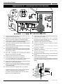
For Your Safety - READ BEFORE LIGHTING:
Proame SIT Electronic Ignition
Lighting Instructions:
phone. Follow the gas supplier's instructions.
If you cannot reach your gas supplier, call the Fire
Department.
C. Use only your hand to push in or turn the gas control knob.
Never use tools. If the knob will not push in or turn by
hand, don't try to repair it, call a qualied service technician.
Force or attempt to repair may result in a re or explosion.
D. Do not use this appliance if any part has been under water.
Immediately call a qualied service technician to inspect
the appliance and to replace any part of the control system,
and any gas control which has been under water.
A. This appliance is equipped with an ignition system that
lights the pilot burner automatically. Do not attempt to light
the pilot by hand.
B. BEFORE LIGHTING smell all around the appliance area for
gas. Be sure to smell next to the oor because some gas is
heavier than air and will settle on the oor.
What To Do If You Smell Gas:
Do not try to light any appliance.
Do not touch any electrical switch; do not use any phone
in your building.
Immediately call your gas supplier from a neighbour's
1. STOP! Read the safety information above on this label.
2. Remove the lower Horizontal access panel.
3. Turn Incoming gas valve to the ON" position.
4. Wait 5 minutes to clear out any gas. If you smell gas,
STOP! Follow "B" in the safety information above on this
label. If you don't smell gas, go to the next step.
5. Turn wall switch "ON".
6. If the Fireplace does not light, the System will cycle through
two trials, (one minute audible clicking, thirty seconds of
silence, and then another one minute of audible clicking).
7. After completion of the information in the Troubleshooting
section, Repeat step 5.
8. If the system will not function correctly, follow the instruc-
tions "To Turn Off Gas To Appliance" and call your service
technician or gas supplier.
EV1 (Pilot
burner)
EV2 (Main
burner)
Pilot Adjust Screw
Lockout Reset Key
Diagnostic Terminal
Power
Command (Wall
switch)
Pilot Sensor
Igniter
Ground
EV1 (Pilot burner)
EV2 (Main burner)
Gas "Out"
Gas "In"
Incoming Gas
Line, Shut-off
Valve
To replace Main
burner
WARNING! If you do not follow these instructions exactly, a re or explosion may
result causing property damage, personal injury or loss of life.

Page 20
C-Series DV Gas Fireplace
Part No. XG0170 - 080610
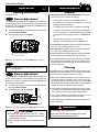
Burner Adjustment
The C-Series DV-F is equipped with an adjustable burner, allowing you
to raise or lower the ames. To adjust the ames, locate the black knob
marked 'Hi-Lo', in the left of the gas control valve (See Figure 32). The
front burners are not adjustable.
■ To raise the ame height, turn the black knob (located behind the
lower trim) counter-clockwise.
■ To lower the ame height, turn clockwise.
Maintenance
Operation
WARNING:
Do not attempt to clean glass when hot.
Do not clean glass with abrasive materials as any glass
etching may cause premature glass failure.
CAUTIONS!
■ Fireplace gas control must be in the “OFF” position
and pilot and main burners extinguished when cleaning
appliance with a vacuum.
■ Doors and logs can get very hot. Handle only when
cool.
General
■ Have the replace and installation inspected yearly. The inspection
must include, but is not limited to, the following:
• A visual check of the entire vent system and termination.
• An inspection of the explosion relief appers and the door
gasketing to ensure a proper seal.
• An inspection of the burner, venturi, and primary air openings.
• An inspection of the gas valve, gas components, and pilot ame.
For your convenience a 1/8" manifold pressure tap is supplied
on the gas valve for a test gauge connection. See Figure 31 &
32.
• Ensure proper log placement as per this manual.
• Inspection of all optional equipment; fans, thermostats, etc.
■ For Natural Gas this appliance requires a minimum inlet pressure
of 5.5" W.C. and a manifold pressure of 3.5" W.C.
■ For Propane Gas this appliance requires a minimum inlet pressure
of 11" W.C. and a manifold pressure of 10" W.C.
■ Always keep the replace area clear and free of combustible materials,
as well as gasoline and other ammable vapors and liquids.
■ Do not use this appliance if any part has been under water. Immediately
call a qualied service technician to inspect the appliance and to
replace any part of the control system and any gas control which
has been under water.
Lighting Instructions
See pages 17 to 19.
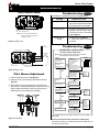
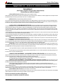
Burner Adjustment
The C-Series DV is equipped with an adjustable burner, allowing you
to raise or lower the ames. To adjust the ames, locate the black knob
marked 'Hi-Lo', in the right of the gas control valve (See Figure 31). The
front burners are not adjustable.
■ To raise the ame height, turn the black knob (located behind the
lower trim) counter-clockwise.
■ To lower the ame height, turn clockwise.
Figure 31. 'Hi-Lo' Adjustment on the C-Series DV's gas valve.
Cleaning
When the replace is rst activated, there may be some smoking and
a visible lm may be left on the glass. This is a normal condition, and is
the result of burning of protective coatings on new metal.
■ Glass must be cleaned periodically to remove any lm (which is
a normal by-product of combustion) which may be visible. Film
can easily be removed by removing the door, as shown on page
15. Handle the door carefully, and clean it with non-abrasive glass
cleaners. One of the most effective products is Kel Kem.
■ Silicone seals on inner door during initial ring will "off gas", leaving
a visual deposit of a white substance on combustion chamber walls.
This can easily be removed using normal household products.
■ Use a vacuum cleaner or whisk broom to keep the control
compartment, burner, and rebox free from dust and lint.
■ Logs may be cleaned periodically with a vacuum to remove soot or
other contaminates.
Note: C-Series DV-I models (electronic ignition) do not feature
hi/lo adjustment.
Figure 32. 'Hi-Lo' Adjustment on the C-Series DV-F's gas valve.
C-Series DV
C-Series DV-I
C-Series DV-F
Manifold Pressure
Test Connection
Pilot Adjustment Screw
Inlet
Pressure
Power
Generator
Wall Switch
Gas Control Knob
(Shown in "Pilot" postion.)
Page is loading ...
Page is loading ...
Page is loading ...
Page is loading ...
Page is loading ...
Page is loading ...
Page is loading ...
Page is loading ...
-
 1
1
-
 2
2
-
 3
3
-
 4
4
-
 5
5
-
 6
6
-
 7
7
-
 8
8
-
 9
9
-
 10
10
-
 11
11
-
 12
12
-
 13
13
-
 14
14
-
 15
15
-
 16
16
-
 17
17
-
 18
18
-
 19
19
-
 20
20
-
 21
21
-
 22
22
-
 23
23
-
 24
24
-
 25
25
-
 26
26
-
 27
27
-
 28
28


Montigo C34-DV Owner's manual
- Category
- Fireplaces
- Type
- Owner's manual
- This manual is also suitable for
Ask a question and I''ll find the answer in the document
Finding information in a document is now easier with AI
Related papers
-
Montigo C38B-I Specification
-
-
-
-
-
-
-
-
-


