
1
IMPORTANT!
DO NOT DESTROY
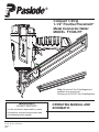
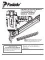
Note: An optional Two Strip Magazine is
available as a service part.
Service part # 502316–Two Strip Magazine
It is the customers responsibility to have
all operators and service personnel read
and understand this manual.
OPERATING MANUAL AND
SCHEMATIC
PRINTED IN U.S.A.
© 2019, Illinois Tool Works Inc.
Compact 1-Strip
1-1/2" Positive Placement
®
Metal Connector Nailer
MODEL F150S-PP
515857-1
0
9/19
®

2
INTRODUCTION
®
TOOL AND FASTENER SPECIFICATIONS ................................................................. 3
SAFETY INSTRUCTIONS ............................................................................................. 4
TOOL INSTALLATION AND OPERATION ................................................................ 5-6
AIR SYSTEMS ............................................................................................................. 7-8
FEATURES AND BENEFITS .......................................................................................... 9
EXPLODED VIEW AND SPARE PARTS LIST ....................................................... 10-11
MAINTENANCE ....................................................................................................... 12-13
TROUBLESHOOTING .................................................................................................. 14
WARRANTY .................................................................................................................. 15
ACCESSORIES ........................................................................................................... 16
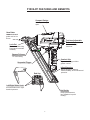
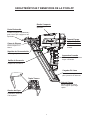
The PASLODE F150S-PP Positive Placement Metal Connector Nailer is a
quality-built tool designed for use in residential framing applications. This tool will deliver
efficient, dependable performance when used according to the manufacturer’s guide-
lines. Please study this manual, including the safety instructions, to fully understand the
operation of this tool.
®

3
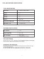
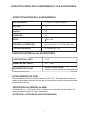
TOOL SPECIFICATIONS
MODEL NO. F150S-PP (Part# 515850)
HEIGHT
11.7"
WIDTH
LENGTH 13"
WEIGHT 6 lbs. 4 oz.
OPERATING PRESSURE 90 to 120 psi (6.2 to 8.3 bar)
FASTENER SPECIFICATIONS
TOOL AIR FITTINGS:
This tool uses a 1/4” N.P.T. male plug. The fitting must be capable of discharging
tool air pressure when disconnected from the air supply.
OPERATING AIR PRESSURE:
90 to120 psi (6.2 to 8.3 bar). Select the operating air pressure within this range
for best tool performance.
DO NOT EXCEED THIS RECOMMENDED OPERATING PRESSURE.
NAIL LENGTH
1-1/2"
SHANK DIAMETER
.131"-.148"
TOOL AND FASTENER SPECIFICATIONS
NAIL COATINGS
Heat Treated,
Galvanized Heat Treated
MAGAZINE TYPE
30 Degree, Strip
3.7"

4
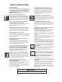
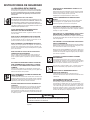
WARNING
Failure to follow any of the above instructions could result in severe personal
injury to tool user and bystanders or cause damage to tool and property.
Contact your local Paslode Representative for a presentation of Paslodeʼs Safety Awareness Program.
SAFETY INSTRUCTIONS
SAFETY FIRST
These safety instructions provide information necessary
for safe operation of Paslode
®
tools. DO NOT ATTEMPT
TO OPERATE THE TOOL UNTIL YOU READ AND
UNDERSTAND ALL SAFETY PRECAUTIONS AND
MANUAL INSTRUCTIONS.
WEAR EYE AND HEARING PROTECTION
Always wear hearing and eye protection devices, that
conform to ANSI Z87.1 requirements, when operating
or working in the vicinity of a tool. As an employer you
are responsible for enforcing the use of eye protection.
Wear hard hats in environments that require their use.
THE TOOL MUST BE USED ONLY FOR THE PUR-
POSE FOR WHICH IT WAS DESIGNED
Do not throw the tool on the floor, strike the housing in
any way or use the tool as a hammer to knock
material into place.
NEVER ENGAGE IN HORSEPLAY WITH THE TOOL
The tool is not a toy so do not use it like one. Never
engage in horseplay with the tool or point it at yourself
or any other person, even if you think it is not loaded.
NEVER ASSUME THE TOOL IS EMPTY
Check the magazine for fasteners that may be left in the
tool. Even if you think the tool is empty or disconnected,
never point it at anyone or yourself. Unseen fasteners
could fire from the tool.
NEVER CLAMP THE TRIGGER IN A LOCKED OR
OPERATING POSITION
The trigger of the tool must never be tampered with,
disabled or clamped in a locked or operating position
since this will cause the tool to drive a fastener any time
the work contacting element depressed.
DO NOT LOAD FASTENERS WITH THE AIR LINE
CONNECTED, OR WITH THE TOOL TRIGGER OR
WORK CONTACTING ELEMENT DEPRESSED
When loading fasteners into the tool be sure you
disconnect the air line and that you do not depress
the trigger or work contacting element.
OPERATE THE TOOL ONLY ON A WORKPIECE
The tool should be operated only when it is in contact
with the workpiece. Even then you should be careful
when fastening thin material or working near the edges
and corners of the workpiece since the fasteners may
drive through or away from the workpiece.
DO NOT DISABLE OR REMOVE THE WORK
CONTACTING ELEMENT
This tool is equipped with a safety mechanism, called a
work contacting element, to help prevent
accidental firing. Never tamper with, disable or remove
the work contacting element. Do not use the tool unless
the work contacting element is working properly. The
tool could fire unexpectedly.
DISCONNECT THE TOOL WHEN NOT IN USE
Always disconnect the tool from the air line when it
is not in use, when you leave the work area or when
moving the tool to a new location. The tool must
never be left unattended because people who are
not familiar with the tool might handle it and injure
themselves or others.
CARRY THE TOOL ONLY BY THE HANDLE
Always carry the tool by the handle only. Never carry
the tool by the air hose or with the trigger depressed
since you could drive a fastener unintentionally and
injure yourself or someone else.
DO NOT WEAKEN THE TOOL HOUSING
The tool housing is a pressure vessel and should never
be weakened by having your companyʼs name, area of
work or anything else stamped or engraved into its
surface.
DISCONNECT THE TOOL WHEN PERFORMING
REPAIRS AND CLEARING JAMS
Never attempt to clear a jam or repair a tool unless you
have disconnected the tool from the air line and
removed all remaining fasteners from the tool.
ALWAYS USE THE PROPER FITTING FOR THE
TOOL
Only MALE pneumatic type air connectors should be
fitted to the tool, so that high pressure air in the tool is
vented to atmosphere as soon as the air line is
disconnected.
NEVER install FEMALE quick disconnect couplings on
the tool. Female couplings will trap high pressure air in
the tool when the air line is disconnected, leaving the
tool charged and able to drive at least one fastener.
DO NOT EXCEED THE MAXIMUM RECOMMENDED
AIR PRESSURE
.erusserp ria dednemmocer eht ta ylno loot eht etarepO
Do
not exceed the maximum air pressure marked on
the tool. Be sure the air pressure gauge is
operating properly and check it at least twice a day.
Never use any bottled air or gases such as oxygen to
operate the tool since they could cause the tool to
explode.
Do not operate in explosive atmospheres.
INSPECT TOOL FOR PROPER OPERATION
.deriuqer sa etacirbul dna yliad tsael ta loot eht naelC
Never operate a dirty or malfunctioning tool.
USE ONLY PASLODE RECOMMENDED PARTS AND
FASTENERS
Use only parts and fasteners specifically designed and
recommended by Paslode for use in the tool and for
work to be done. Using unauthorized parts and
fasteners or modifying the tool in any way creates
dangerous situations. Replace all missing warning
labels---refer to tool schematic for correct placement
and part number.

5
TOOL INSTALLATION
Your Paslode tool comes ready for immediate use
and can be installed by following these steps:
1. SAFETY - All tool operators and their immediate
supervisors must become familiar with the operator
safety instructions before operating the tool. The
instructions are on page 4 of this manual.
2. Included with each tool is a copy of the operation
manual and schematic.
Keep this publication for
future reference. An ownership registration card is
also included. This card must be completed and
returned to Paslode immediately to register your
ownership.
3. The plastic cap in the air inlet of the tool must be
removed before the male fitting is installed. The fit-
ting must be a male pneumatic type that discharges
the air from the tool when the air line is discon-
nected.
4. Install a filter/regulator/lubricator unit, with a
gauge as close as practical to the tool, preferably
within ten feet. Refer to the Air Systems section of
this manual for air hose requirements and lengths.
In general, no other special installation is required.
5. If the operator is working at a bench or table,
it is usually best to run the air line underneath the
bench. A small tray under the benchtop can hold
the fastener supply and the tool when not in use.
6. If this tool does not work when it is first connect-
ed, do not try to make repairs. Call your Paslode
representative immediately.
TOOL OPERATION
■
Depress the work contacting element and hold
it against the work surface before pulling the
trigger.
■
After each fastener is driven, completely release
the trigger and lift the tool from the work surface.
Driving of Nails
The tool is equiped with a sequential (gray) trigger
to operate the tool.
Step No. 1- Grasp the nailer handle firmly.
Loading of Nails
Step No. 2- Insert one strip of fasteners into
the rear of the magazine with the point of the
nails facing the nose area.
Step No. 3- Pull the follower to the rear of the
magazine until it is engaged behind the nails.
The tool is now ready to use.
Use only fasteners that meet Paslode specifications.
Use of fasteners that do not meet Paslode specifications
can result in damage to the tool or injury to the operator
or bystanders.
WARNING
Note:
Follow the metal connector manufacturer’s
instructions when installing the nails. Always
use the nail size specified by the metal
connector manufacturer and/or the local
building codes.

6
TOOL OPERATION -
continued
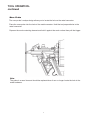
Nose Probe
The nose probe’s unique design allows you to locate the hole on the metal connector.
Place the nose probe into the hole of the metal connector. Hold the tool perpendicular to the
metal connector.
Depress the work contacting element and hold it against the work surface then pull the trigger.
Note:
The probe is a wear item and should be replaced when it can no longer locate the hole in the
metal hardware.
6
TOOL OPERATION -
continued
Nose Probe
The nose probe’s unique design allows you to locate the hole on the metal connector.
Place the nose probe into the hole of the metal connector. Hold the tool perpendicular to the
metal connector.
Depress the work contacting element and hold it against the work surface then pull the trigger.
Note:
The probe is a wear item and should be replaced when it can no longer locate the hole in the
metal hardware.

7
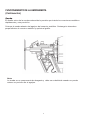
AIR SYSTEMS
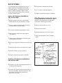
For air-powered tools to work their best, the air
supply system must be properly installed and
maintained regularly. A drawing in this section
shows a properly installed air supply system.
Handy checklists for installing and maintaining
air supply systems follow.
Indoor Air System Installation
-Be certain that:
• All pipes supplying air have a large enough
inside diameter to ensure adequate air supply.
• The main supply pipe slopes down, away from
the compressor (1/16 inch per foot).
• Air storage is provided along lengthy air lines.
• Pipe line branch outlets are at the top of the
main pipe line.
• Cutoff valves are provided at each branch pipe
line throughout the system.
• Water legs extend from the bottom of each branch
line.
• A refrigerant-type dryer is installed on the system.
• Air hoses are kept as short as practical.
• A regular maintenance program is followed.
Outdoor Air System Installation
-Be certain that:
• A moisture trap and a filter/regulator/lubricator are
installed at the compressor.
• Air hoses and fittings are large enough so that air
flow is not restricted. Minimum hose size is 3/8
inch ID with 1/2 inch ID hose used for any
application over 25 feet.
• Air hoses are not longer than 150 feet.
• The air system is lubricated regularly.
• A regular maintenance program is followed.
Filter/Regulator/Lubricator Units
Filter/regulator/lubricator units that can supply
enough air and protection for Paslode tools
must meet the following specifications:
• Minimum 3/8 inch NPT port size .
• 50 micron or fine filters.
• Regulated pressure from zero to 120 psi.
• Lubricators designed for low or changing
airflow.

8
AIR SYSTEMS - Continued
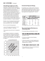
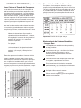
Calculating Compressor Size
Use the air consumption chart in the Tool
Schematic for each tool when calculating the
operating requirements for the tools.
Paslode
tools are designed to operate efficiently
between 80 and 120 psi and should never be
operated at pressure greater than 120 psi.
The air consumption chart will help you find the
correct compressor size for your application
that will quickly replenish tool air pressure.
To use the chart you will need to know how
many tools will be used and approximately
how many fasteners will be driven each minute
by each tool onthe line. Using the equation:
Number of tools X average fasteners/minute/
tool X 1.2 (safety factor) X air consumption
(scfm) @ pressure* (psi) = scfm required.
We can use the following example:
10 tools X 30 fasteners/minute/tool X 1.2 X
0.051scfm* (@100psi) = 18.36 scfm.
*This number is found in the Air Consumption
Chart
In this example, using the air consumption
chart we find that a compressor providing at
least 19 scfm of air is required. Because in
compressors approximately 1 hp is required to
produce 4 scfm, a compressor of at least 5 hp
is required.
Calculated Required Piping
For example, given a 20 hp electric compressor
supplying approximately 80 cfm of air at 120 psi
and a main supply pipe length of 350 feet, we see
by the table the minimum main pipe inside diam-
eter required for this
application is 1-1/4 inch.
Pneumatic System Maintenance
- Be certain that:
• Pneumatic fittings are tight and do not leak.
and ensure that automatic draining systems are
operating correctly.
• Air lines are cleared to prevent freezing,
especially in winter.
• Lubricator operation is checked regularly and
ensure it has an adequate supply of lubricant.
(Paslode Part No. 403720)
• Only regulated air is being used and that each
regulator is operating properly.

9
F150S-PP FEATURES AND BENEFITS
Tool-less Adjustable
Exhaust Cap
Deflects air away
from user.
Bypass Follower
For fast loading
Nose Probe
Comfort Grip
Ergonomic design provides
greater comfort.
Locates hole and
guides nail as it is
driven.
Compact Design
Nail Guide
Helps guide fasteners
into magazine for quick
loading.
Sequential Trigger
Lock-Out
Eliminates blank firing.
Promotes driver blade
durability.
Left/Right Rafter Hook
Accommodates left-or right-
handed operators.
End Cap
Inline Magazine
Narrow design for balance,
maneuverability, and unobstructed
operation.
Able to get into tight
spots.

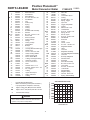
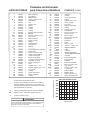
PARTS LEGEND
F150S-PP
515850
▲
1
502330 1 Main Valve Nut
2
502304 1 Air Deflector
3
502343 1 Wave Washer
4
502339 4 S.H.C.S. #10-24 x 7/8”
rehsaW talF7 203804 5
6 502303 1 Cap
7 502313 1 Gasket, Cap
8 360594 1 Spring,
* 9
gniR-O 1 283202
*10
201806 1 O-Ring
*11 539676 1 O-Ring
*12
13
502056 1 Exhaust Seal Assembly
14
1011802 1 Washer
15
502327 1 B.H.C.S. 1/4-20 x 1-1/2”
16
502311 1 Piston Seal
17
502309 1 Sleeve,Cylinder
*18
egnalF ,gniR-O 1 179290
02*
192799 1 O-Ring, Flange
*21
502310 1 Check Band
22
502317 1 Bumper
24
502302 1 Housing W/Overmolded grip
*26
502345 1 S.H.C.S. 5/16-18 x 5/8”
27
502034 1 Label, Housing RIGHT
30
502305 1 End Plug, Housing
*28
502035 1 Label, Housing-Left
402963 1
29
32
502336 2 S.H.C.S. #10-24 x 1”
33
515851 1
34
380931 1 Roll Pin 3/16 x 1-1/2”
*35
502333 1 Roll Pin, Trigger 1/8 x 1-1/2”
*37
197913
1 O-Ring
502044 1
*38
502059 1 Spring, Valve Pin
39
1015358
1 O-Ring
*40
502045 1 Valve Pin
41
196345 1 O-Ring
*42
502043 1 Lower Valve Spool
43
092747 1 O-Ring
44
403796 1 Roll Pin 1/8”x 1-1/4”
45
502060 1 Spring, Trigger
▲
46
502225 1
S.H.C.S. 1/4-28 x 1/2”
*47
502224 1 Trigger, Sequential
48
502042 1 O-Ring
49
091866 2
Roll Pin 1/8” x 3/4”
50
002187 5 Lock Washer
*51
091545 4 S.H.C.S. 1/4-20 x 7/8”
52
502328 1
53
reppU .E.C.W 1 123205
54
502337 1 S.H.C.S. 1/4-20 x 3/8”
55
404800
1 Flat Washer
*56
502325 1
57
511059 1
58
502320 1
59
502338 2
61
515855 1 Label
442681 1 Lock Nut
511883 1 Magazine Assembly
*19
502307 1 Flange
60
502323 1
Magazine Washer
23
-- ------------------
502332 1 Rafter Hook
*
Denotes Normal Wear Items
**
Make sure Warning Label (Part No.502917)
is properly affixed. Replace if necessary.
▲
Apply Loctite 242 (Blue) Part N o. 093500
■
Denotes New Change
WARNING
All parts must be periodically inspected and replaced if
worn or broken. Failure to do this can affect the toolʼs
operation and present a safety hazard.
AIR CONSUMPTION CHART
AIR CONSUMPTION-SCFM FASTENER
AIR PRESSURE-PSIG
25
31
36
502324 1 Pin, Trigger
.120
.110
.080
.090
.100
120
.060
.070
06 07 08 09 001 011
➔
**
.086
502033 1
O-Ring, Housing End Plug
W.C.E. Guide Block
Nose
Upper Valve Spool
Trip Lever
Spring, W.C.E.
Probe Pin
Probe
W.C.E., Lower
Positive Placement
Metal Connector Nailer
Drum Pin Assembly
Negator Spring
▲
62
62B
63
502316 1 Two Strip Magazine Assembly
64
092037 1 Lock Nut
65
502329 1 End Cap, Magazine
66
511183 1 Follower Claw
67
68
502025 1
69
502017 1 B.H.C.S 1/4-20 x 3/4”
70
502928 1
Logo Label
72
502335 1
B.H.C.S. 8-32 x 1/2”
73
502347 1 S.H.C.S. 10-32 x 5/8”
74
502020 1 Spring, Follower Body
1 Follower Body
75
502318
71
500627 1
Lockout Bar
502226
1
502340 1 Spiral Pin
▲
▲
▲
▲
▲
®
▲
*
®
®
Apply
Loctite 620 (Green) Part
No. 401491
----------
➔
10
PARTS LEGEND
PF150S-PP
502300
▲
1
502330 1 Main Valve Nut
2
502304 1 Air Deflector
3
502343 1 Wave Washer
4
502339 4 S.H.C.S. #10-24 x 7/8”
5 408302 7 Flat Washer
6 502303 1 Cap
7 502313 1 Gasket, Cap
8 360594 1 Spring,
* 9
202382 1 O-Ring
*10
201806 1 O-Ring
*11 539676 1 O-Ring
*12
13
502056 1 Exhaust Seal Assembly
14
1011802 1 Washer
15
502327 1 B.H.C.S. 1/4-20 x 1-1/2”
16
502311 1 Piston Seal
17
502309 1 Sleeve,Cylinder
*18
092971 1 O-Ring, Flange
*20
192799 1 O-Ring, Flange
*21
502310 1 Check Band
22
502317 1 Bumper
24
502302 1 Housing W/Overmolded grip
*26
502345 1 S.H.C.S. 5/16-18 x 5/8”
27
502034 1 Label, Housing RIGHT
30
502305 1 End Plug, Housing
*28
502035 1 Label, Housing-Left
402963 1
29
32
502336 2 S.H.C.S. #10-24 x 1”
33
502306 1
34
380931 1 Roll Pin 3/16 x 1-1/2”
*35
502333 1 Roll Pin, Trigger 1/8 x 1-1/2”
*37
197913
1 O-Ring
502044 1
*38
502059 1 Spring, Valve Pin
39
1015358
1 O-Ring
*40
502045 1 Valve Pin
41
196345 1 O-Ring
*42
502043 1 Lower Valve Spool
43
092747 1 O-Ring
44
403796 1 Roll Pin 1/8”x 1-1/4”
45
502060 1 Spring, Trigger
▲
46
502225 1
S.H.C.S. 1/4-28 x 1/2”
*47
502224 1 Trigger, Sequential
48
502042 1 O-Ring
49
091866 2
Roll Pin 1/8” x 3/4”
50
002187 5 Lock Washer
*51
091545 4 S.H.C.S. 1/4-20 x 7/8”
52
502328 1
53
502321 1 W.C.E. Upper
54
502337 1 S.H.C.S. 1/4-20 x 3/8”
55
404800 1 Flat Washer
*56
502325 1
57
511059 1
58
502320 1
Drum Pin Assembly
59
502338 2
Negator Spring
▲
61
502917 1 Label
62
442681 1 Lock Nut
63
502316 1 Magazine Assembly
64
092037 1 Lock Nut
65
502329 1 End Cap, Magazine
66
511183 1 Follower Claw
67
68
502025 1
69
502017 1 B.H.C.S 1/4-20 x 3/4”
70
502928 1
Logo Label
*19
502307 1 Flange
72
502335 1
B.H.C.S. 8-32 x 1/2”
73
502347 1 S.H.C.S. 10-32 x 5/8”
74
502020 1 Spring, Follower Body
1 Follower Body
60
502323 1
Magazine Washer
23
1 Blade Seal
75
502332 1 Rafter Hook
*
Denotes Normal Wear Items
**
Make sure Warning Label (Part No.502917)
is properly affixed. Replace if necessary.
▲
A
pply Loctite 242 (Blue) Part N o. 093500
■
A
pply Loctite 620 (Green) Part
No. 401491
Denotes New Change
WARNING
All parts must be periodically inspected and replaced if
worn or broken. Failure to do this can affect the toolʼs
operation and present a safety hazard.
AIR CONSUMPTION CHART
AIR CONSUMPTION-SCFM FASTENER
AIR PRESSURE-PSIG
502318
25
31
36
502324 1 Pin, Trigger
71
500627 1
.120
.110
.080
.090
.100
120
.060
.070
06 07 08 09 001 011
➔
**
.086
502033 1
O-Ring, Housing End Plug
W.C.E. Guide Block
Nose
Upper Valve Spool
Trip Lever
Spring, W.C.E.
Probe Pin
Probe
W.C.E., Lower
Lockout Bar
502226
1
502340 1 Spiral Pin
Positive Placement
Metal Connector Nailer
▲
▲
▲
▲
▲
®
▲
*
®
®
511587
➔

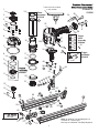
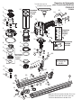
F150S-PP
47
46
45
44
48
Trigger
Assembly
#502253
Seal must be installed
in this position.
*
42
33
40
39
37
36
35
41
38
Trigger
Valve
Assembly
#502908
43
Piston
Assembly
#515853
1
2
3
4
5
6
7
8
9
10
11
12
13
14
15
16
26
24
23
21
19
18
17
25
27
28
29
5
30
31
52
51
48
55
54
49
53
50
49
34
32
65
66
64
63
62
57
56
59
58
67
72
71
68
74
73
75
60
69
Tor
IN/LBS
70
5
15
62B
20
180
80
140
210
80
90
140
70
#502920
*
61
100
120
515850
11
20
Note: An optional Two Strip Magazine is
available as a service part.
Service part # 502316–Two Strip Magazine

12
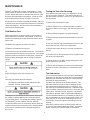
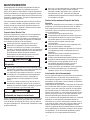
MAINTENANCE
Paslode
®
tools are built for ease of maintenance. A few
simple details will assure trouble-free operation and long
tool life. Anyone who uses or maintains the tool must read
the safety and maintenance instructions. Study the sche-
matic drawing before starting any repairs on the tool.
Air-operated tools must be inspected periodically, and worn
or broken parts must be replaced to keep the tool operating
safely and efficiently. Also the items on the maintenance
chart must be checked often.
Cold Weather Care
When temperatures are below freezing, tools should be
kept warm by any convenient, safe method. If this is not
possible, the following procedure should be used to warm
up the tools.
❑ Reduce the regulated air pressure to 30 psi.
❑ Remove all fasteners from the tool.
❑ Connect an air line and blank fire the tool. The reduced
air pressure will be enough to free-fire the tool. Slow speed
operation tends to warm up the moving parts. Slowing up
the piston helps the bumper and the O-rings to become
springy.
❑ Once the tool is warmed up, readjust the regulator to the
proper working pressure and reload the tool.
❑ Tool operators working outdoors or in unheated areas in
extremely cold temperatures should also:
Use Paslode pneumatic oil with antifreeze in the
lubricator, Part No. 219090 (8oz.)
Cleaning the air-operated tools with solvents removes the
thin coating of grease applied to the cylinder wall and
O-rings at the factory. To replace this coating of grease,
use Chemplex grease (Paslode Part No. 403734).
❑ Open the drain on the air compressor tank to drain any
moisture at least daily in extremely cold or humid weather.
A few ounces of antifreeze in the tank will keep the air
free of frost.
Testing the Tool After Servicing
After replacing any part or parts, it is important to check
the tool for proper operation. This ensures that the tool
was put together correctly, is safe to use, and will perform
the job properly.
❑ Ensure that all hardware is tight.
❑ Ensure that the work contacting element is installed
correctly in relation to the trigger, and that both parts move
freely.
❑ Ensure that the magazine is properly attached.
❑ Ensure that the required safety information on the tool
is legible.
❑ Use only Paslode approved fasteners in the tool, and
ensure that they are correct for the application.
❑ Ensure that a male air fitting is securely connected to
the tool.
❑ Test the tool by driving fasteners into a workpiece iden-
tical to the tool's application.
❑ Check the tool for air leaks during testing and for the
proper sequence of operation.
❑ Ensure that all fasteners are driven to the same depth
and that the crown of the fastener is flush with the work-
piece.
Tool Lubrication
It is most important that the tool be properly lubricated by
keeping the air line lubricator filled and correctly adjusted.
Without proper lubrication the tool will not work properly
and parts will wear prematurely.
Use the proper lubricant in the air line lubricator. The
lubricator should be of low air flow or changing air flow
type, and should be kept filled to the correct level. Use
only Paslode recommended lubricants. Substitutes may
harm the rubber compounds in the tools O-rings and other
rubber parts. Paslode Part No. 403720 is a pneumatic
lubricating oil specially made for pneumatic applications.
If a filter/regulator/lubricator is not installed on the air sys-
tem, air operated tools should be lubricated at least once
a day with 6 to 20 drops of oil, depending on the work
environment, directly through the male fitting in the tool
housing.
Most minor problems can be resolved quickly and eas-
ily using the maintenance table that follows. If problems
persist, contact your Paslode dealer for assistance.
®
®
®
®
®
®
®
12
MAINTENANCE
Paslode
®
tools are built for ease of maintenance. A few
simple details will assure trouble-free operation and long
tool life. Anyone who uses or maintains the tool must read
the safety and maintenance instructions. Study the sche-
matic drawing before starting any repairs on the tool.
Air-operated tools must be inspected periodically, and worn
or broken parts must be replaced to keep the tool operating
safely and efficiently. Also the items on the maintenance
chart must be checked often.
Cold Weather Care
When temperatures are below freezing, tools should be
kept warm by any convenient, safe method. If this is not
possible, the following procedure should be used to warm
up the tools.
❑ Reduce the regulated air pressure to 30 psi.
❑ Remove all fasteners from the tool.
❑ Connect an air line and blank fire the tool. The reduced
air pressure will be enough to free-fire the tool. Slow speed
operation tends to warm up the moving parts. Slowing up
the piston helps the bumper and the O-rings to become
springy.
❑
proper working pressure and reload the tool.
❑
extremely cold temperatures should also:
Use Paslode pneumatic oil with antifreeze in the
lubricator, Part No. 219090 (8oz.)
Cleaning the air-operated tools with solvents removes the
thin coating of grease applied to the cylinder wall and
O-rings at the factory. To replace this coating of grease,
use Chemplex grease (Paslode Part No. 403734).
❑ Open the drain on the air compressor tank to drain any
moisture at least daily in extremely cold or humid weather.
A few ounces of antifreeze in the tank will keep the air
free of frost.
Testing the Tool After Servicing
After replacing any part or parts, it is important to check
the tool for proper operation. This ensures that the tool
was put together correctly, is safe to use, and will perform
the job properly.
❑ Ensure that all hardware is tight.
❑ Ensure that the work contacting element is installed
correctly in relation to the trigger, and that both parts move
freely.
❑ Ensure that the magazine is properly attached.
❑ Ensure that the required safety information on the tool
is legible.
❑ Use only Paslode approved fasteners in the tool, and
ensure that they are correct for the application.
❑ Ensure that a male air fitting is securely connected to
the tool.
❑ Test the tool by driving fasteners into a workpiece iden-
tical to the tool's application.
❑ Check the tool for air leaks during testing and for the
proper sequence of operation.
❑ Ensure that all fasteners are driven to the same depth
and that the crown of the fastener is flush with the work-
piece.
Tool Lubrication
It is most important that the tool be properly lubricated by
keeping the air line lubricator filled and correctly adjusted.
Without proper lubrication the tool will not work properly
and parts will wear prematurely.
Use the proper lubricant in the air line lubricator. The
lubricator should be of low air flow or changing air flow
type, and should be kept filled to the correct level. Use
only Paslode recommended lubricants. Substitutes may
harm the rubber compounds in the tools O-rings and other
rubber parts. Paslode Part No. 403720 is a pneumatic
lubricating oil specially made for pneumatic applications.
If a filter/regulator/lubricator is not installed on the air sys-
tem, air operated tools should be lubricated at least once
a day with 6 to 20 drops of oil, depending on the work
environment, directly through the male fitting in the tool
housing.
Most minor problems can be resolved quickly and eas-
ily using the maintenance table that follows. If problems
persist, contact your Paslode dealer for assistance.
®
®
®
®
®
®
®

13
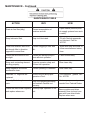
MAINTENANCE - Continued
Drain air line filter(daily).
Keep lubricator filled.
Clean filter element-then blow
air through filter in direction
opposite to normal flow.
Check that all screws on tool
are tight.
Keep work contacting element
working properly.
Keep magazine and feeder
mechanism clean.
Lubricate "O" rings that are
replaced.
Use only Paslode replacement
parts.
ACTION
WHY
HOW
MAINTENANCE TABLE
Prevent accumulation of
moisture and dirt.
Keep tool lubricated.
Prevent clogging of filter with
dirt.
Prevent air leakage and pro-
mote efficient operation.
Promote operator safety and
efficient tool operation.
Prevent jamming of fasteners.
Assure long life and proper
operation of tool.
Keep tool operating efficiently
and maintain Paslode tool
warranty.
Open manual petcock (most
air supply systems have such
a valve).
Fill with Paslode pneumatic
tool lubricant. Part No.
403720.
Wash with soap and water or
follow manufacturers instruc
-
tions.
Check screws daily.
Blow clean daily.
Blow clean daily.
Use Chemplex grease, Part
No. 403734.
Order any repacement parts
needed from Paslode Dealer.
Check the driver blade regularly
and replace when worn.
Ensure proper operation of the
tool.
Remove piston and driver
assembly from tool and com-
pare with new driver blade.
Replace when worn.
®

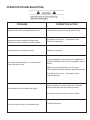
14
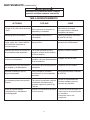
OPERATOR TROUBLESHOOTING
PROBLEM CORRECTIVE ACTION
Fasteners will not drive completely into wood.
Fasteners penetrate properly during normal
operation, but won't drive fully at faster speeds.
Fasteners drive too deeply into wood.
Tools skips during operation - no fasteners are
driven from time to time.
Tool operates, but no fasteners are driven.
Air leaks at cap when tool is connected to air.
Increase air pressure (do not exceed 120 psi).
Increase air flow to tool -- use larger air lines
(3/8 inch ID minimum).
Reduce air pressure.
Check magazine for proper fasteners. Magazine fol-
lower should slide freely. Clean as needed to remove
debris.
Make sure correct fasteners are being used.
Use fasteners that meet Paslode
®
specifications only.
Increase air flow to tool -- use larger air lines
(3/8 ID minimum).
Check magazine for proper fasteners. Fasteners
should slide freely with no follower pressure.
Increase air pressure (do not exceed 120psi).
Tighten capscrews.
30
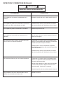
DETECCION Y CORRECCION DE FALLAS
14
PROBLEMA SOLUCIÓN
Los sujetadores no penetran completamente en la
madera.
Los sujetadores penetran bien durante las operaciones
normales, pero fallan a velocidades más altas.
Los sujetadores penetran demasiado en la madera.
Los sujetadores se acumulan en la punta de la her-
ramienta.
La herramienta “salta” mientras está funcionando; de
vez en cuando no impulsa sujetadores.
La herramienta funciona, pero no dispara sujetadores.
Hay pérdidas de aire en la cubierta cuando la herra-
mienta está conectada a la línea de aire.
Aumente la presión de aire (no debe exceder 120 psi).
Aumente el flujo de aire a la herramienta; use líneas
de aire más grandes (3/8” de diámetro como mínimo).
Reduzca la presión de aire.
Abra el seguro delantero, quite el sujetador obstruido y
cierre bien el segurro.
Compruebe si el cargador tiene los sujetadores apro-
piados. El transportador debe deslizarse sin dificultad.
Límpielo para quitar cualquier suciedad.
Verifique que se usen los sujetadores apropiados.
Use solamente sujetadores que reúnan las especifica-
ciones de Paslode.
Aumente el flujo de aire a la herramienta; use líneas
de aire más grandes (3/8” de diámetro como mínimo).
Compruebe si el cargador tiene los sujetadores apro-
piados. Los sujetadores deben deslizarse libremente
sin presión del transportador.
Abra el seguro delantero o afloje el botón del cargador
y revise si hay suciedad o alguna obstrucción en el
área de la punta. Límpiela si es necesario.
Aumente la presión de aire (no debe exceder 120 psi).
Apriete los tornillos.
PRECAUCIÓN
Desconecte la herramienta al hacer cualquier
reparación o eliminar cualquier obstrucción.
14
OPERATOR TROUBLESHOOTING
PROBLEM CORRECTIVE ACTION
Fasteners will not drive completely into wood.
Fasteners penetrate properly during normal
operation, but won't drive fully at faster speeds.
Fasteners drive too deeply into wood.
Tools skips during operation - no fasteners are
driven from time to time.
Tool operates, but no fasteners are driven.
Air leaks at cap when tool is connected to air.
Increase air pressure (do not exceed 120 psi).
Increase air flow to tool -- use larger air lines
(3/8 inch ID minimum).
Reduce air pressure.
Check magazine for proper fasteners. Magazine fol-
lower should slide freely. Clean as needed to remove
debris.
Make sure correct fasteners are being used.
Use fasteners that meet Paslode
®
specifications only.
Increase air flow to tool -- use larger air lines
(3/8 ID minimum).
Check magazine for proper fasteners. Fasteners
should slide freely with no follower pressure.
Increase air pressure (do not exceed 120psi).
Tighten capscrews.

15
An Illinois Tool Works Company
155 Harlem Avenue
Glenview,IL 60025
TOOL WARRANTY AND LIMITATIONS
TOOL WARRANTY
P
than
•
Probe
MODEL F150S-PP
15
An Illinois Tool Works Company
155 Harlem Avenue
Glenview,IL 60025
TOOL WARRANTY AND LIMITATIONS
TOOL WARRANTY
P
than
•
Probe
MODEL PF150S
15
An Illinois Tool Works Company
155 Harlem Avenue
Glenview,IL 60025
TOOL WARRANTY AND LIMITATIONS
TOOL WARRANTY
P
than
•
Probe
MODEL PF150S

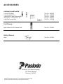
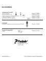
L
ubricants and Loctite
Loctite 242 (Blue)
Part No. 093500
Lubricating Oil 16 oz.
Part No. 403720
Lubricaing Oil with Antifreeze 8 oz. Part No. 219090
Chemplex 710 Lubricant 1lb.
Part No. 403734
Tool Cleaner
Ideal cleaner for all Paslode tools. Part No. 219348
Safety Glasses
Clear Part No. 401382
ACCESSORIES
®
®
Lubricant 5 gram tube
Part No. 219188
Paslode and Positive Placement are registered trademarks of ITW.
All other trademarks are property of their respective owners.
®
®
®
An Illinois Tool Works Company
155 Harlem Avenue
Glenview,IL 60025
P

17
¡IMPORTANTE!
NO DESTRUYE ESTE MANUAL
El cliente tiene la responsabilidad de que
todo el personal de operaciones y servicio
lea y entienda este manual.
Manual de Funcionamiento y
Esquema
®
Note: Una Revista opcional de Dos Tiras está
disponible como parte de servicio. Pieza de
servicio # 502316-Revista de Dos Tiras
Clavador de Conector Metálico
1-Tira Compacta 1-1/2"
Colocación Positiva®
MODELO F150S-PP

18
INTRODUCCIÓN
La clavadora Paslode F150S-PP para conectores metálicos es una herramienta de
calidad, diseñada para uso en aplicaciones residenciales.
Esta herramienta le provera un rendimiento fiable cuando sea usada en acorde
con las reglas del fabricante.
Lea cuidadosamente este manual y las instrucciones de seguridad para comprender como
usar la herrmienta correctamente.
CONTENIDO
SPECIFICACIONES DEL LA HERRAMINETA Y SUS SUJETADORES.............................3
INSTRUCCIONES DE SEGURIDAD................................................................................... 4
INSTALACION Y OPERACION DE LA HERRAMINETA..................................................5-6
SISTEMAS DE AIRES......................................................................................................7-8
BENEFICIOS DE LA HERRAMIENTA................................................................................ 9
ESQUEMA CON LISTA DE PIEZAS DE REEMPLAZOS.............................................10-11
MANTENIMIENTO.........................................................................................................12-13
DETECCION Y CORRECION DE FALLAS........................................................................14
GARANTIA.........................................................................................................................15
ACESORIOS.......................................................................................................................16
2

19
ESPECIFICACIONES DE LA HERRAMIENTA
NO. de MODELO F150S-PP (Pieza# 515850)
ALTURA 11.7"
ANCHO "7.3
DUTIGNOL 13"
PESO
lbs. 4 oz.
PRESIÓN de OPERACIÓN 90 hasta 120 p.s.i. (6.2 hasta 8.3 bar)
TIPO de CARGADOR
30 Grados, en Tira
ESPECIFICACIONES de los SUJETADORES
ACOPLAMIENTO DE AIRE:
Esta herramienta utiliza un tapón macho de 1/4" N.P.T. El acoplamiento debe ser
adatcenocsed aes odnauc atneimarreh al ne eria ed nóiserp al ragracsed ed zapac
del suministro de aire.
OPERACION de PRESIÓN de AIRE:
90 hasta120 p.s.i. (6.2 hasta 8.3 bar). Seleccione una presión de aire dentro de
esta gama para obtener el mejor rendimiento.
NO EXCEDA LA PRESIÓN DE AIRE RECOMENDADA.
LONGITUD DEL CLAVO 1-1/2"
DIAMETRO DEL TALLO .131" - .148"
ESPECIFICACIONES DE LA HERRAMIENTA Y LOS SUJETADORES
3
Tratados Térmicamente,
Tratados Térmicamente en Galvanizado
ACABADOS DEL CLAVO

20
PELIGRO
La falta de observación de cualquiera de estas instrucciones puede ser causa de graves
lesiones personales, tanto al operador de la herramienta comoa quienes estén cerca de
ella o de daños materiales o a la herramienta
.
Comuníquese con el representante de Paslode sobre la presentación de Programa de Alerta sobre
Seguridad.
LA SEGURIDAD ESTA PRIMERO
Estas instrucciones proporcionan la información necesatia para el
funcionamiento sin peligrode las herramientas Paslode. NO trate
de usar su herramienta hasta que no haya léido y entendido
todas las precauciones de seguridad y las instrucciones de
este manual.
PROTEJASE LOS OJOS Y LOS OIDOS
Use siempre el equipo adecuado para protegerse los ojos
y los oídos que sea conforme con ANSI Z87, meintras usa
una herramienta o trabaja cerca de una herramienta en
uso. Como empleador usted es responsable de imponer el
usp del la porteccion de ojo. Lleve sombreros duros en los
ambientes que requieren su uso.
USE SU HERRAMIENTA SOLAMENTE PARA EL
PROPOSITO CON QUE FUE DISEÑADA
No arroje la herramienta al suelo; no golpee el armazón ni la use
como un martillo.
NUNCA USE LA HERRAMIENTA PARA JUGUETEAR
Esta herramienta no es un juguete; por lo tanto no la trate como
tal. Nunca juguetee con ella, ni se apunte a usted mismo ni a otra
persona, aun cuando crea que no está cargada.
NUNCA ASUMAQUE LA HERRAMIENTA ESTA VACIA
Verfique que ho haya sujetadores en elcargador. Aun cuando crea
que está vacía o desconectada, nunca se apunte ni apunte a otra
persona con la herramienta, porque podría dispararse un sujetador
que no esté a la vista.
NUNCA SUJETE EL GATILLO EN LA POSICION DE
CIERRE O DE FUNCIONAMIENTO
Nunca se debe manipular indebidamente o dejar inoperante el
gatillo, o sujetarlo en la posición de cierre o defuncionamiento,
porque se podría disparar un sujetador al oprimirse el elemento de
contacto.
NO CARGUE SUJETADORES CUANDO LA LINEA DE
AIRE COMPRIMIDO ESTE CONECTADA, O CUANDO
EL GATILLO O EL ELEMENTO DE CONTACTO ESTE
OPRIMIDO.
Antes de cargar sujetadores en la herramienta, verifique que la
línea de aire comprimido esté desconectada y que ni el gatillo ni el
elemento de contacto estén oprimidos.
USE LA HERRAMIENTA SOLAMENTE SOBRE UN MA-
TERIAL DE TRABAJO
La herramienta debe funcionar sólo cuando esté en contacto con el
material de trabajo. Debe tener mucho cuidado cuando el material
sea delagado o trabaje cerca de las aristas del mismo, porque los
sujetadores podrían atravesar o salirse del material.
NO DEJE INOPERANTE NI QUITE EL ELEMENTO DE
CONTACTO
Esta herramienta está equipada con un mecanismo de seguridad,
llamado elemento de contacto, para prevenir cualquier disparo
accidental. Nunca manipule indebidamente, deje inoperante, ni
quite el elemento de contacto. No use la herramienta a menos que
dicho elemento funcione correctamente, porque podría producirse
un disparo imprevisto.
DESCONECTE LA HERRAMIENTA CUANDO NO LA
ESTE USANDO
Siempre desconecte la herramienta de la línea de aire comprimdo
cuando no la esté usando o al dejar su lugar de trabajo. Nunca la
descuide, porque cualquier persona que no esté
familiarizada con ella podría lastimarse o lastimar otros.
TOME LA HERRAMIENTA SOLAMENTE POR EL
MANGO
Siempre tome la herramienta sólo por el mango. Nunca la tome
por la manguera o con el gatillo oprimido, porque se podría
disparar un sujetador y herirlo o herir a otra persona.
NO ALTERE EL ARMAZON DE LA HERRAMIENTA
El armazón de la herramienta es un recipiente a presión y nunca se
debe grabar en su superficie el nombre de su compañia, el del área
de trabajo, ni ningún otro detalle.
DESCONECTE LA HERRAMIENTA PARA HACER
REPARACIONES O ELIMINAR OBSTRUCCIONES
Nunca trate de eliminar obstrucciones o reparar una herramienta
sin haberla desconectado de la línea de aire compromido y quitado
todos los sujetadores.
USE SIEMPRE LOS ADAPTADORES APROPIADOS
PARA SU HERRAMIENTA
Se debe conectar a la herramienta solamente conectores neumáticos
MACHOS, para permitir que el aire de alta presíon salga tan pronto
como se desconecte la línea de aire comprimido.
NUNCA coloque enlaces HEMBRAS de desconexíon rápida en la
herramienta, porque atrapan el aire a alta presíon al desconectar
la línea de aire comprimido, dejándola cargada y lista para disparar
por lo menos un sujetador.
NO EXCEDA LA PRESION NEUMATICA MAXIMA
RECOMENDADA
La herramienta debe funcionar sólo con la presíon neumática
recomendada. No exceda la presíon neumática máxima marcada
en la herramienta. Verifique por lo menos dos veces al día que el
calibre de la presíon neumática funcione correctamente.
Nuna use aire o gases envasado, como el oxígeno, para hacer
funcionar la herramienta porque podrían hacer que explotara.
INSPECCIONE LA HERRAMIENTA PARA LA
OPERACION APROPIADA
Limpie diariamente la herramienta y lubríquela como se
recomienda. Nunca trate de hacer funcionar una herramienta sucia
o defectuosa.
USE SOLAMENTE PIEZAS Y SUJETADORES
RECOMENDADOS POR PASLODE
Use sólo piezas y sujetadores específicamente diseñados y
recomendados por Paslode para usar con esa herramienta y para
la tarea requerida. Si se usan piezas o sujetadores no autorizados
o se modifica de alguna forma la herramienta, se pueden crear
situaciones peligrosas. Vuelva a colocar todas las etiquetas de
precaucíon que flaten. Consulte el diagrama de la herramienta sobre
el número de cada parte y su ubligación correcta.
INSTRUCCIONES DE SEGURIDAD
4
Page is loading ...
Page is loading ...
Page is loading ...
Page is loading ...
Page is loading ...
Page is loading ...
Page is loading ...
Page is loading ...
Page is loading ...
Page is loading ...
Page is loading ...
Page is loading ...
-
 1
1
-
 2
2
-
 3
3
-
 4
4
-
 5
5
-
 6
6
-
 7
7
-
 8
8
-
 9
9
-
 10
10
-
 11
11
-
 12
12
-
 13
13
-
 14
14
-
 15
15
-
 16
16
-
 17
17
-
 18
18
-
 19
19
-
 20
20
-
 21
21
-
 22
22
-
 23
23
-
 24
24
-
 25
25
-
 26
26
-
 27
27
-
 28
28
-
 29
29
-
 30
30
-
 31
31
-
 32
32


Ask a question and I''ll find the answer in the document
Finding information in a document is now easier with AI
in other languages
- español: Paslode 515850 Manual de usuario
Related papers
-
Paslode T250S-F16P User manual
-
-
-
-
-
-
Paslode 515600 User manual
-
-
-
Other documents
-
 Smarter Tools ST-LX6010 User manual
-
 DUO-FAST FloorMaster 200-C Operating Manual And Schematic
-
DUO-FAST DF350S User guide
-
 DUO-FAST 502950 User manual
-
 Berkling Tools BT 2443J User manual
-
POWERNAIL 2000 Pneumatic Powernailer User guide
-
-
-
-
Impulse IM200 F18 User manual


