Page is loading ...

MT–XLR MT–XLR
Reference ManualReference Manual
Reference ManualReference Manual
Reference Manual
Reference ManualReference Manual
Reference ManualReference Manual
Reference Manual
MT-XLR
© 2001 by Crown Audio, Inc., P.O. Box 1000, Elkhart, IN 46515-1000 U.S.A.
Telephone: 219-294-8000. Fax: 219-294-8329. The MT-XLR module is
produced by Crown Audio, Inc. Trademark Notice: Power-Tech
™
is a
trademark and Crown
®
, Amcron
®
, CSL
®
, Power Base
®
Macro-Tech
®
and
Micro-Tech
®
are registered trademarks of Crown International. Other
trademarks are the property of their respective owners.
MT
-
XLR
CH-2 INPUT CH-1 INPUT
PUSHPUSH
3
12
GND
THESE XLR INPUTS ARE CONNECTED IN PARALLEL WITH THE PHONE JACK INPUTS.
For Technical Support contact:
Crown Technical Support Group
Plant 2 SW, 1718 W. Mishawaka Rd., Elkhart, Indiana 46517 U.S.A.
Phone:
800-342-6939800-342-6939
800-342-6939800-342-6939
800-342-6939 (North America, Puerto Rico and Virgin Islands)
or 219-294-8200 Fax: 219-294-8301 Internet: http://www.crownaudio.com
FRONT
BOTTOM VIEW
J1
ROUTE THE MT-XLR CABLE
THROUGH THE SAME HOLE
AS THE RIBBON CABLE.
MT-XLR
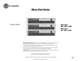
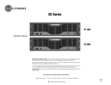
Fig. 2.2 Installing an MT-XLR
Page 4
PPPrinted on
recycled paper.
130656-1
10/01
phone jacks and level control
knobs clear the back panel.
Then carefully lift the rear of the
board to expose its top side (Fig-
ure 2.2).
5. Insert the MT-XLR cable through
the back panel opening, and
through the same chassis hole
where the ribbon cable is routed.
6. Plug the MT-XLR connector into
J1 on the main board. J1 is the
five-pin header located immedi-
ately behind the Ground Lift
Switch. The wires at the connec-
tor should face the rear.
7. Fasten the MT-XLR panel in
place using the screws provided
and reassemble the amplifier by
reversing steps 4 through 2.
IMPORTANT: Make sure no
wires impede the fan rotation.
8. Restore power to the unit and re-
adjust the level controls.

MT–XLR MT–XLR
Reference ManualReference Manual
Reference ManualReference Manual
Reference Manual
Reference ManualReference Manual
Reference ManualReference Manual
Reference Manual
FROM
SOURCEINPUT
–
+
3
1
2
GND
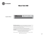
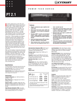
Fig. 1.1 MT-XLR
MT
-
XLR
CH-2 INPUT CH-1 INPUT
PUSHPUSH
3
12
GND
THESE XLR INPUTS ARE CONNECTED IN PARALLEL WITH THE PHONE JACK INPUTS.
2 Installation
CAUTION: This input accessory
panel should only be installed by
qualified service personnel in the
following manner:
1. Turn down the level controls
(fullly counterclockwise), turn off
the amplifier and unplug it from
the AC power source.
2. Remove the filter/grill from the
front panel (3 Phillips screws).
Remove the cover plate from the
back panel (2 Phillips screws).
3. Lay the amplifier upside down
and remove the bottom cover
(8 Phillips screws).
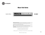
4. Locate the main board (Figure
2.1) and remove the two Phillips
screws which secure it to the
chassis. Remove the nuts which
secure the input phone jacks to
the rear panel. Slide the main
board toward the front until the
FRONT
BOTTOM VIEW
MAIN BOARD
REMOVE SCREW REMOVE SCREW
Fig. 2.1 Inside a Micro-Tech
1 Welcome
The MT-XLR accessory panel is
designed to give your Micro-Tech
®
,
Power Base
®
, Power-Tech
™
and
CSL
®
amplifiers the same bal-
anced XLR inputs which are stan-
dard for a Macro-Tech
®
amplifier.
Installation requires access to the
top side of the main circuit board
and should only be attempted by
a qualified technician.
The female XLR connectors are
wired with the following pin assign-
ments:
Pin 1 Signal Ground
Pin 2 Positive (+) Input (non-in-
verting)
Pin 3 Negative (–) Input (invert-
ing)
Balanced and unbalanced input
wiring is shown in Figures 1.2 and
1.3. Notice that a jumper should
Fig. 1.3 Unbalanced
Input Wiring
Fig. 1.2 Balanced
Input Wiring
FROM
SOURCEINPUT
+
3
1
2
SHIELD
WARNING: TO PREVENT
ELECTRIC SHOCK, THIS
ACCESSORY SHOULD
ONLY BE INSTALLED BY
QUALIFIED SERVICE
PERSONNEL.
be installed between pins 1 and
3 when connecting an unbal-
anced source.
Page 2 Page 3
/