Page is loading ...

STORMSHELL
AssemblyandInstallationInstructionsfor44"StormShellTV
HardCoverandWallMount

Caution
Prior to installation of this product, the installation instructions should be read and
completely understood. The installation instructions must be read to prevent personal injury
and property damage. Keep these installation instructions in an easily accessible location for
future reference.
This mount and hard cover contains small parts which can act as a choking hazard if
swallowed.
CAUTION: The maximum TV load capacity is 33 lbs. (15 kg). Use with products exceeding the
maximum load capacity may cause serious injury.
The wall structure must be capable of supporting at least five times the maximum load
capacity as indicated. If not, the wall must be reinforced.
Recommended mounting surfaces: wood stud and solid-flat concrete/brick. If the mount is
to be installed on any surface other than wood studs, solid concrete or brick, use suitable
hardware (not included but commercially available).
Do not install on a structure that is prone to vibration, movement or chance of impact.
Failure to do so could result in damage to the display and/or damage to the mounting
surface.
Do not install near heater, fireplace, air conditioning or any other heat producing source.
Failure to do so may result in damage to the display and/or the hard cover and could
increase the risk of fire.
Make sure no water or natural gas lines are present where the mount is to be installed.
Cutting or drilling into water or natural gas lines could cause personal injury or property
damage.
Proper installation procedure by yourself or a qualified service technician, as outlined in the
installation instructions, must be adhered to. Failure to do so could result in serious personal
injury.
When mounting to a wall that contains wood studs, confirm the dead center of the wood
stud prior to installation, it is recommended that the wood studs be a minimum of 16" apart
(if applicable).
It is recommended that two people perform the installation. Injury and/or damage can result
from dropping or mishandling the display.
If you don't understand these installation instructions, please consult an installation
specialist.

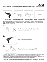
ToolsRequired
Electronic stud finder for drywall installation
Phillips head screw driver or electric drill
Bubble Level
13 mm socket and wrench
Electric drill, 18
⁄
" and 14
⁄
” drill bit for wood stud installation.
CenteringtheStormShellHardCover–AdapterMountingPlate
The 44” Storm Shell hard cover and TV wall mount are designed to be installed on solid concrete or
brick or on wood studs. For wood stud installation, the 44” Storm Shell is designed for installation
on three studs spaced 16” apart as shown in Figure 1. If a different placement of the 44” Storm
Shell is required to center the TV in a particular space, or if the wall studs are built at 20” spacing,
then an Adapter Mounting Plate will be required. Please consult Item “44 Storm Shell Adapter
Mounting Plate”, as shown on StormshellTV.com/Products.
Figure1
ConcreteorBrickInstallation
When installing the Storm Shell Hard Cover and TV Bracket on a concrete or brick wall, the provided
S7 and S8 screws alone will not be sufficient. Do not attempt to use the supplied S7 and S8 screws
alone on masonry or concrete.
Several options are commercially available for concrete or brick anchors. Options include concrete
sleeve anchors or concrete screws. Consult your local hardware store or online resources to
determine the best solution for your specific wall material. Obtain proper anchors and screws to
replace the S7 and S8 screws.

StormShellandTVMountingBracketParts
1.StormShellFront1pc 2.StormShellBack1pc 3.TVbracket(preassembled
inStormShellBack) 1set
Screws:
No. Name QTY Picture No. Name QTY Picture
S1 M6X10 Screw 4
S8 ST8.0X60
Self Tapping
Screw
3
S2 M8X10 Screw 4
W1 3-hole
Washer
4
S3 M5X25 Screw 4
W2 Thick
Washer
4
S4 M6X25 Screw 4
W3 D8 Washer 3
S5 M8X25 Screw 4
W4 D6 Washer 2
S6 ST3.5X20 Self
Tapping Screw
12
B1 Buckle
Latch
4
S7 ST6X30 Self
Tapping Screw
4
B2 Extension
Bar
4
M6
10
10
M8
25
M5
M6
25
25
M8

PreparetheStormShellBack
Remove the TV bracket from the Storm Shell Back by unscrewing the two shipping screws
(Figure 2).
Assemble the four buckle latches (B1) onto the Storm Shell Back using the S6 screws (Figure
3).
Figure2
Figure3
InstalltheStormShellBackontothewall
Two people are needed for this installation.
A) WoodStudInstallation
1. Use a high quality electronic stud finder (commercially available) to locate dead center of three
adjacent wood studs spaced 16” apart. Mark the location of each stud (Figure 4). Note: If a
different placement of the 44” Storm Shell is required to center the TV in a particular space, or if the
wall studs are built at 20” spacing, then an Adapter Mounting Plate will be required. Please
consult Item “44 Storm Shell Adapter Mounting Plate”, as shown on StormshellTV.com/Products.
Figure4
2. Determine the height location for the top of the TV mounting display. Mark this height on the
center of the mounting stud positioned furthest to the right. Drill a hole into the stud at this
location using a 18
⁄
” drill bit 1.5 inches deep. Screw one of the S7 screws into this location,
leaving the head about 18
⁄
” away from the wall. Note: if the TV display is smaller than the 44”
Screws:
S6: ST3.5X20: 12
p
cs
B1: Buckle Latch

Storm Shell (for example, a 32” display), you may need to adjust the location of this mounting screw.
This mounting screw will be placed in the top right keyhole of the Storm Shell Back – see Figure 5
below.
3. Lift the Storm Shell Back to the wall and position the S7 screw head (Step 2) into the top right
keyhole (Figure 5). Place a bubble level on top of the Storm Shell Back and rotate until the Storm
Shell Back is Level. Place a mark on the wall through the top left keyhole. Make sure to mark the
top left key hole at the center of the top (where the screw will rest). Remove the Storm Shell Back
from the wall and check to ensure that the mark for the top left keyhole is centered on a stud.
Repeat the procedure in Step 2 to drill and screw an S7 screw for the top left keyhole. Mount the
Storm Shell Back on the wall using the mounted screws and the top left and right keyholes. Check
that the Storm Shell Back is level using the bubble level.
Figure5
4. Place a mark through the Storm Shell Back onto the wall in the remaining five (5) mounting
locations (Figure 6). Remove the Storm Shell Back from the wall and ensure that the five (5)
remaining mounting location marks are located over a stud. For position B, use the same drill
procedure as Step 2 (1/8” drill bit 1.5 inches deep). For position A, drill a hole using a 1 4
⁄
” drill bit,
3 inches deep.
Figure6 – Storm Shell Back Mounting Locations
A
A
A
B
B
B
B
Top Right Keyhole
Top Left Keyhole

5. Hang the Storm Shell Back on the wall. Use a 13 mm socket and wrench to attach the TV
Bracket using the S8 screws and the W3 washers (note the washers are placed between the S8
screw head and the TV Bracket mounting hole). See Figure 7.
Figure7
6. Secure the Storm Shell Back to the wall by installing two (2) S7 screws and two (2) W4 washers
in the lower mounting holes (Figure 8). Tighten the S7 screws in the upper left and right keyholes.
Figure8
Screws:
S8- ST8.0X60: 3 pcs
W3- D8 Washer: 3 pcs
Screw:
S7- ST3.5X20: 2pcs
W4-D6 washer: 2pcs

7. Install the Storm Shell Front and check that cover and latches fit correctly. Figure 9.
Figure9
B) ConcreteorBrickInstallation
When installing the Storm Shell Hard Cover and TV Bracket on a concrete or brick wall, the S7 and S8
screws alone will not be sufficient. Do not attempt to use the supplied S7 and S8 screws alone on
masonry or concrete.
Several options are commercially available for concrete or brick anchors. Options include concrete
sleeve anchors or concrete screws. Consult your local hardware store or online resources to
determine the best solution for your specific wall material. Obtain proper anchors and screws to
replace the S7 and S8 screws.
The installation procedure for concrete or brick is the same as for wood stud installation with the
following exceptions:
Locating three wood studs is not required. Determine the desired location for the Storm
Shell Hard Cover and proceed at Step 2, using the selected concrete anchors.
InstalltheTVDisplay
Caution:ThisTVbracketcanbeusedforaTVupto44".ThemaximumweightoftheTVdisplay
shouldbelessthan33lbs.(15kg.).
The installation kit includes screws of various diameters to ensure optimal installation.
Figure 10 shows the parts of the TV Bracket.

Figure10
1. Place the TV display screen down on a soft, flat surface. Locate the four (4) threaded
mounting points that are located on the back of the display (called the VESA mounting holes).
2. Determine which screw (S3/S4/S5) is the proper size for the VESA mounting holes.
3. If the TV display has a curved back, or recessed VESA holes, the W2 Thick Washer can be used as
needed.
4. Determine the VESA mounting hole pattern dimensions. Typical dimensions are 200 mm x 200
mm (7 7/8” x 7 7/8”), 400 mm x 400 mm (15 34
⁄
” x 15 34
⁄
”), 200 mm x 400 mm (7 7/8” x 15
34
⁄
”).
5. The Extension Bars (B2) on the TV Bracket can be configured to match the corresponding VESA
hole pattern. When the Extension Bars (B2) are removed from the Hook Plate, the Hook Plate
will accommodate a 200 mm x 200 mm VESA hole pattern. Other configurations are shown in
Figure 11.
Figure11
6. Remove the Hook Plate from the Swing Arm by removing the two securing screws at the
connection of the Hook Plate to the Swing Arm (Figure 12):
400mm
400mm
480mm
200mm
200mm
480mm
Hook plate
Swing arm
B2: Extension bar

Figure12
7. Configure the Extension Bars (B2) as desired. If the TV display has a 200 mm x 200 mm
VESA pattern, skip this step. Use the S1 and S2 screws to secure the Extension Bars (B2) as
shown in Figure 13.
Figure13
8. Fix the Hook Plate and Extension Bars to the back of the TV Display by connecting the proper
screw (S3/S4/S5) into the VESA holes. Select the proper washer (W1/W2/W3) to be used
with the screws. Figure 14.
Figure14
9. Lift the TV Display (with the Hook Plate firmly attached to the back) and slide the Hook Plate
in place on the Swing Arm (Figure 14). Replace the securing screws that were removed in
Step 6.
Screws:
S1- M6X10 Screw: 4pcs
S2- M8X10 Screw: 4pcs

SetTVCables
Figure15
/