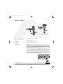
Dormont Mfg A200 Pressure Vacuum Breaker is a reliable device designed to protect your water system from backflow and contamination. Capable of handling pressures up to 150psi, it ensures uninterrupted water flow while preventing potentially hazardous backflow situations. Its versatile design allows for installation in various settings, including sprinkler systems, with a minimum clearance of 12 inches above the highest point of downstream piping. Regular testing and maintenance, as outlined in the manual, are crucial for optimal performance and longevity.
Dormont Mfg A200 Pressure Vacuum Breaker is a reliable device designed to protect your water system from backflow and contamination. Capable of handling pressures up to 150psi, it ensures uninterrupted water flow while preventing potentially hazardous backflow situations. Its versatile design allows for installation in various settings, including sprinkler systems, with a minimum clearance of 12 inches above the highest point of downstream piping. Regular testing and maintenance, as outlined in the manual, are crucial for optimal performance and longevity.


-
 1
1
-
 2
2
-
 3
3
-
 4
4


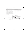
Dormont Mfg A200 Pressure Vacuum Breaker is a reliable device designed to protect your water system from backflow and contamination. Capable of handling pressures up to 150psi, it ensures uninterrupted water flow while preventing potentially hazardous backflow situations. Its versatile design allows for installation in various settings, including sprinkler systems, with a minimum clearance of 12 inches above the highest point of downstream piping. Regular testing and maintenance, as outlined in the manual, are crucial for optimal performance and longevity.
Ask a question and I''ll find the answer in the document
Finding information in a document is now easier with AI
Related papers


Other documents
-
Watts 912HP 1 Installation guide
-
Ames Fire & Waterworks A200 Installation guide
-
Ames Fire & Waterworks 200B 2 Installation guide
-
-
Febco 767FR 1 1/2 Installation guide
-
Toro 53300 User manual
-
Ames Fire & Waterworks A100-AVB 1 Installation guide
-
Watts 2000S-M5 3/4 Installation guide
-
Innova PF6011-SS-SD Installation guide
-
Watts M300N(A)-DOSY-C 2 1/2 Installation guide