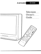
Sony KV-36FV26 Owner's manual

Type
Owner's manual

This manual is also suitable for

I
WARNING
re :educe the :isk of fi:o or shock hazarc do not expose the "IV to
_ain or mols[ure
ATTENTION
RISQUE DE CHOC ELECTRIQUE
NE PAS OUVRER
PRECAUCION
RIESGO DE CHOQUE ELECTR_CO
NC _RER
CAUIION: 10 REDUCE IHE RISK OF £L[CTRIC SHOCK
DO NO]" REMOVE COVER (OR BACKk
NO USER-SERVICEABLE PARTS INSIDE.
REFER SERVICING TO QtlAI.IFIEB SERVICE pERSONNEL
This symbol is intended to alert the user to the
presence of uninstgated "dangei ous voltage
within the product's enclosm_ that may be of
sufficient magnaude to constitute a risk ot
electric shock to persons
This symbol is intended to alert the user to the
presence ofimpoi rant operating and mainter_ance
servicing) irlsti uctions in the literature
accompanying the appliance
CAUTION
FO PREVENT ELECTRIC SHOCK MATCH WIDE BLADE DF
PLUG TO WIDE SLOT FULLY INSERT
CAUTION
When using TV games, computers, and similar products with your
PV keep the brightness and conh-ast functions at tow settings, If a
!ixPd [non InovingJ I IttPrn Js left on tho screen for long periodsof
[tnle at a nigb brigbEness or contrast setting, tb_ irrlage can De
aermanently imprinted onto the screen Continuously watching
tbe same program can cause [no imprint of station loges onto the
PV screen Those types of imprints are not ¢'overed by youi
warran D DPeause [ney are the result Df Fi1isuse
Note on CaptionVision
Phis television receiveI provides display _f television chxsed
captioning in accordance wah §15.119 of the FCC rules
Note on Cleaning the TV
Cleat] the TV with a soft dry qoth Never use strong solvents such
_s thinner or benzine, which might damage the finish of the
Note to CAIV System Installer
the reminder is provided to call the CATV system instaIler s
_ttendon to Araele 820 40 of the NEe that provides guidelit ms fo_
proper grounding and, in par tietliar, specifies that the cable glound
_hall bPconnected to tbe groundblg system of the building, as clos_
o me point of cable ent]3r as practical
Use of this television receiver for other than pi irate viewing of
arog] _ms broadcast on UItF ox VItF or transmitted by cable
corn I mies for the use of the general public may ieqube
_uthorization flom the broadcaster/cable compan 3 and/or
arogram owner
NOTiFiCATION
Fhis equipment has been tested and found to {'omply with th_
[imas for a Class g digital device pursuant to Pair 15 of the FCC
Rules These gmas are designed to provide ieasonable pro[er[mn
against harmful interference in a residential installation. This
equipment geneiams uses and can radiate radio fequency energy
mid if not installed and used in accordance with the instructions
may cause ha_ mful h]ter repel]re wah iadio eonllIlunieations
[towever there is no guarantee that interfoience will not occur in a
particular instaganon If this eqmpment does cause harmful
mterfoienre to Iadio or television rpcepEton whh'b can be
determined by lu_nlngme eqmpment offand on me userIs
encouI aged to try to COlTPCtthe inter ferenee by 3no or more of the
rogowmg measures
Reorient or relocate the receiving antennas
_.] Increase die separanol I between the equlplnen[ anti receiver.
k_ Connect the equi f _lent into an outlet on a _irc nit different
from that to which the receiver is connected
{_ Consult the dealer or an experienced radio f[_ technician for
help.
You am (autioned that any changes or modigcations nol
expressly approved in this manual could void youi authority
m ope_ ate this equipmenL
Safety
kJ Operate tile TV only m 120 V AC
kJ The plug is designed for safety purposes to fit into the wall
ounot only one way, If you are unable to insert the plug fully
into the outlet contact your dealer
LJ if any liquid or solid ob Pet should fall inside the cabinet
unpmg the TV immediately and have it checked by qualified
servlc_ personnel he fern operanng it further
Installing
J To prevent internal heat buildu f do not block the vennIatkm
openings
_1 Do not install the TV in a hot oi hu mid place, or in a place
suoject to excesMve dust or mechanical vibration
-1 The AC power cord is attached to the i oar of the TV with
hooks Do not attempt to remove the cord fiom these hooks
Doing so could cause damage to the TV
AS an ENER(,y STAR®Partne r
Sony has determined that this
pi OdtlCt or product models meets
the EN_Ra¥ S'IARa guideline,
for energy efficiency
ENER;YStAg _is a U.S reg]smre_ lnarK
(o)_ SRSSound Retrieval System
The 10) SRS {SOUND RETRIEVAL SYSTEM is manufactm_d by
Sony Coi poration under license fom SRS Labs in< It is covered by
US. Parent No. 4 _48.669 Other US. and foreign patents pending
fhP word "SRS" and the SRS symbol {0) are registorod trademaiks
of SRS Labs Inc
Licensed by BBE Sound. Inr under USP 46382584482866 aBE and
abe symbol axe trademarks of aBE Sound In_
gD Trinaron and the Wega logo are trademarks of Sony
Corpm ation
Owner's Record
The model and s_rial numbers ai_ provided on the front of thi_
instruction manual and at the iear of the T_Z RPfF,r to them
whenever you tail upon your Sony dealei regarding this product.
About this Manaal
fhis manuatis for models KV32FV16 KV32FV2f KV36FSI2 KV
36FS16 KVSGFVI6 and KV36FV26 The menu and illustrations
shown are for model KV36FV26 to show the maximum features
available Differences in operation will be indicated in the text for
example, "For KV 36FV26 only"
Important Safeguards
For your protection, please read these instmcUons compIetely, and
keep this manual for future reference¸
Car_fogy observ_ and comply with all wai nings, cautions and
_nstructions placed On the s_t or described in the opei aTmg
instru_*Uons or service man_lai
WARNING
To guard against mjur3_ the following basic safety precautions
should be observed in the insr.lilation usa and servicing of the set
use
Power Sources
['his set should be operated only from the type
of power source indicated on the serial/model
3fate, If you are not sure of the type of electrical
_ower supl)tied to your holrle, corlsuU your
dealer or local power compan3_ For those sets
clestgnecl _o op_Iat_ from battery powoi i_far
o [ne operating ins[i uc[lons
Grounding or Polarization
[`his set is equipped with a polarized AC power cord plug (a plug
qavmg ane blade wider alan the otho or wltn a [gtl'eO v41re
grounding type plug {a plug Caving a third pin fo_
grounding Follow the instructions below:
For the set with a polarized AC power cord plug
['his plug wig fit into the power outlet only one ,/_ _
way Thisisasafetyfeatulx,.If} )umeunabl_to _]-
insm't the plug fully into thp outlet. [l'y reversing
Cleaning
Unplug =tieset froln tile wall outlet hefore
cleaning polishing it. Do not rise liquid
cleaners or aerosol cleaners Use a cloth ligntty
oampened with water for cleaning me exterior
of the set
|nstaHation
Attachments
[ _ ]lot Use atta_h[n_nts not reco_rli_PndPd by [n_
manufacturer as they may cause hazaids
Water and Moisture
Do not use powerline operatecl sets near
water for exampm near a bathtub
wasnt}owt kitchen sink or laundry tul). in a
wet basemen[ or near a swnllming pool, etc
the plug If the plug still fails to fit con[art your electrician to have
Accessories
[ 3 not pl*lce the set on an unstablF" Tart s[anQ
table or sheI£ The set may fall, causing serious
LnJury to a chUd o_ ¸an adult and serious damage
[o the sat Use only a cart or .stand recommended
suitable outlet installed. Do not d_faat the safety put pose of the _y die manufacturer fo[ the specific model of T_
3olarized plug by forcing it in An appliance and cart combination should be
[110VeCl wl[n [:are QLlick stops exces._ive forc_
ARtetnate Warn_t_ and uneven surfaces may cause the applian¢ e and
cart combine[loll to ove[ [ltrn
For the set with a three-wire grounding type AC plug
This plug witl only fit into a grounding type
power outlet This is a safety feature. If you are
anabte to insert the plug
youI electrician to have a su aabie outlet installed
Do not defeat the safety puIpose of the grounding plug
Overloading
Do not ovei load wall outlets, extension cords or
-onvenience receptacles beyond theh capacity, []7Q_,_ -.._ _
since this c....... U]ng ....... lectrk' shock. _.5_
Always tuzn the set off when it is not being
3_e_I.When the set is left unattended and g_<_'__"
.mused for long periods of tim_ u_lplug it _" ;_<_/_,_1__/_'_
!rom the wall oudet as a precaut,on against _ _gJ
the possibility of an internal nlalfuncnon that
-ould create a file hazard
Ventilation
l'he slots and opening_ in the caBinet and in the back or Bottom are
provided for necessar} ventilation. To ensure i eliable opei ation of
the set ariel _o protect it from ovedloaUng these slots and openings
must never be Blocked or covei_d.
if a snapping o[ popping sound from a TV s_t is
:onUnuous or frequent while the TV is operating
tmplug the TV and consuU you]" dealer or service
ochnician tt is normal for some TV sets to make
occasional snapping or popping sounn,
aarUcuIarty when being turned on or off
Never rover the slots and openings wl[n a
cloth or other materials.
d Never block the sIots and openings by
placing me set on a _)on. sofa itlg or ethel"
sitnilar surfacp
J Never place the set in a confined space such
as a Bookcase oi Built in cabinet unless
proper ventilation is I rovided
9 -, kl Do not place thp sot near oi over a iadiator
'_ or heat register, or where it is exposed tc
Object and Liquid Entry
Novel push objects of any kind into the set _ .
.hrough the cabinet slots as they may touch _1_
dangerous voltage points or short out parts that
could result in a fire or electric shock Never spill
liquid of any kind on the set
Power-Cord Protection
Do not allow anytlting to iest on or iolI over the
power cmd and do i_ot t lace the set where the _F_-_ -
power coId is subject to wear or abuse _L_flj_
Antennas
Outdoor Antenna Grounding
[fan outdoor antmma is installed, follow the precautions below. An
outdoor antenna system should not be located in the, icinit y of
S_'v]ee
Damage Requiring Service
Unplug "he set from the wag outlet and refm servicing to qualigpd
seI vice personnel under the following conamons
d When th_ f Jwer cord or plug
is damaged or frayea _;g_,
El If liquid has been spgled into A_L_ :_A¢_ £_
tile set
overhead power lines or other electric light or power circuits or
where it call come in contact with such powei liner oi eil'_uits
WHEN INSTALLING AN OUTDOOR ANTENNA SYSTEM
EXTREME CARE SHOULD BETAKEN TO KEEP FROM
CONTACTING SUCH POWER LINES OR CIRCUITS AS
CONTACT WITH THEM tS ALMOST INVARIABLYFATAL
El If tile sot has been exposed to
rain or 1A/ales
Be sure the antenna system is grounded so as to provtgle SOtlle
_rotecUon against voltage surges arid built up static ('narges.
Section 810 of the Natiorkll Electrical Code [NECt in USA and
Section 54 of the Canadian Electrical Code in Canada pmvide_
information with respect to proper grounding of the mast and
supporting structure, gi ou nditlg of the lead in wire to an antenna
dischaige unit siz_ of grounding conductors location of antenna
dischalge unit connection to gIounolng electrodes and
requirements for the grounding electrode
Antenna Grounding According to the NEC
Refi_r to section 54 S00 of Canadian Electrical Code for Antenna
Grounding
[fthe_ot has been su[ or[to
excessive shock l y oetng
aroppPo _rthecabinethas
bPPn _amageG
If the set does not opera[e
normally when following th_
operating irlstructions Adjusl
only those controls that ar_
specified in the opera_mg
instructions¸ Improper
adjustment of other contmh
may result in damage ann
wilt often require extensive
work by a qualified wchnician
to restore the set to normal operation
El When the set exhibits a distinct change in per foi monte, it
_ An[ennalead _nwire )ndicates a need for service.
// "11 oltageoroiherhazard .Rof ,r llsorvi ingto(fr;X ,J
! _ ] ,_ quagfied service personnel. '_/"
r ir r h ,,
kntennateacHnwre wRep{a_eme_tPnart_eepace e tea tsae equ' ed, besu et ese_!ce
NEC Nattonal Eect, ca Code Powe so vce 0undng eec ode _pc_'_f_e_bcy`_PIe_s_n'_u`f_a`c_tiu`neg_t_;'at_'_hvas_usesd_'p_c_ce_an;_ent_p::_a_
system _NECArt 250 Pan the origUlal parts
Unautholized substitutions ma 3 ]esult in fire electric shDck or
other hazards.
Lightning
For added I [election for this television receiver during a lightning
_mrm or wlwn it is left unattended and unused for long periods of
tme unplug it from tile wall outlet and disconnect tile antenn_
fhis will aravent aamage to tile receivei due to lightning ariel
power line surges
Safety Check
Upon completion of any sei vice or iepairs to the
se[ ask tile service technician to perform routine (
safety checks (as specified by the manufacturer/to L
determine that the set is in salt, opei anng
conomon and to so certiI_ 'When the set reaches
the end of its us_fuI life impmpe_ dis_ asal r'ould
resin[ tn a picture mop mq lesion Ask a qualifie_
SOl.ice technician to dispose of the set
Contents
ln_roduc/ng the FD Trin rron Wege Usino the Menus
Overview ................................................................ 1 Overview .............................................................. 35
Presenting the FD Ttinitron Wega ......................2
Using the Remote Control ...................................3
Instafltng the TV
Overview ................................................................ 7
TV Controls and Connectors ............................... 8
Connecting a Cable oi" Antenna ........................ 10
Using the Video Menu .......................................36
Using the Audio Menu ......................................38
Using the Channel Menu ...................................40
Using the Parent Menu ......................................42
Using the Timer Menu .......................................45
Using the Setup Menu ........................................47
Using the Basic Menu .........................................49
Connecting a VCR and Cable ............................14
Connecting a VCR and Cable Box ....................15 Other Information
Connecting Two VCRs for Tape Editing .......17
Connecting a Satellite Receiver .........................18
Connecting a Satellite Receiver with a VCR.., 19
Connecting an Audio Receiver ........................ 21
Connecting a DVD Player with Component
Video Connectors ................. 22
Connecting a DVD Player with
A/V Connectors ..................................... 23
Connecting a Camcorder ...................................24
Using the CONTROL S Feature ........................25
Setting Up the TV Automatically ....................26
Overview ........................................................... 5]
Troubleshooting .......... 57
Specifications .......................................................59
Index .................................................................. 61
Usino the Features
Overview .............................................................. 27
Using Favorite Channels .................................... 28
Using Picture in Picture P1PI .......................29
Using Wireless Headphones .............................32
v
Overview
This chapter defines the contents of your Wega TV and provides an
overview of how to set up and use basic features.
Topic Page
Presenting the FD Trinitron Wega 2
Contents 3
Using the Remote Control 3
1
Introducing the FD Trinitron Wega
Presenting the FD Trinitron Wega
The FD Trinitron Wega tpronounced VAY-GAHI is characterized by
outstanding contrast, uncompromising accuracy, and corner-to
corner detail.
You'll recogmze the superiority of Wega technology almost
immediately. The first thing you'll notice is minimal glare from the
flat picture tube. This fiat-screen technology improves picture detail
"without distortior unlike conventional curved screens. The FD
Trinitron delivers outstanding image detail not only at the screen
center but also at the corners so you can enjoy a bright, clear
picture from any location in a room.
Features
Some of the features that you will enjoy with your new TV include:
L.I 16:9 Enhancement: Vertical Compression technology that
maximizes picture resolution on "anamorphic" or "enhanced for
widescreen" sources, including selected DVDs.
J Velocity Modulation: Vertical line enhancement that sharpens
picture definition.
d Steady Sound: Equalizes volume levels so there is consistent
output between programs and commercials.
J Parental Control: V-Chip technology allows parents to block
unsuitable programming for younger viewers.
J Component Video Inputs: Offers the best video quality for DVD
player connections.
.J S-VIDEO Inputs: Provides a high-quality image for connected
equipment.
d Dual Tuner Picture in Picture (PIP): Allows you to watch two
programs at once _except model KV-36FS121.
d Favorite Channel Preview: Preview up to eight favorite channels
without leaving the current channel Lexcept model KV-36FS121.
U Wireless Infrared Headphones: Enjoy listening to programs
without disturbing anyone else models KV-32FV26 36FV26
only,
2
Contents
Introducing the FD Trinitron Wega
Your box contains your new Trinitron TV. a remote control and two
AA batteries. No peripheral cables are included with this TV. Please
check the hookup instructions for your desired setup before you
begin. You may need to purchase cables and/or splitters to complete
the hookup properly.
Models KV-32FV26 and 36FV26 also contain wireless headphones
and one additional AA batterv.
Using the Remote Control
Inserting Batteries Insert two size AA {R61batteries isupplied) by matching the + and -
on the batteries to the diagram inside the battery compartment.
3
Introducing the FD Trinitron Wega
Button Descriptions_
sYs_
®®0
®®®
®®®
50'8
@
_ _e--7-_ O
VOL CH
MUTING Mutes the sound. Press again or press V0L+ to restore
the sound.
(GREEN) equipment,
........................................................n0 o,kw!!h equipment'!....................................
FUNCTIONbuttons Select the equipment (TV,VCR/DVD_ SAT/CABLE)
(WHITE orBLACK) that you want to operate, The indicator lights up
momentarily when pressed to show which device the
remote control is operating,
" TV/VIDEO
Model Remog:e
KV-36FS16 RM-Y169 * DVDMENL
KV-32FV16and36FV16RM-Y171 * TITLE
KV-36FS12 RiVI-YI68 ANT
KV-32FV26and36FV26RM-YI7O
PICTUREMODE
_ YettowPicture-in-Picture
DUt[OnSnlgnllgnteo adore [ grit)
arenotavailableontheRM-Y16{
remote_odelKV-36FS12,
Buttonswithastedsks_ inthet_st
are tocaten on[Re nstae oanet Of
SLEEP
Cyclesthrough the video equipment connected to your
TV's video inputs
Displays the DVD menu
Displays the DVD's Title menu.
Changes the VHF/UHF input to the AUX input.
Cycles through the available video picture modes: Vivid
Standard.Movie.Sports,Also available in the Video menu.
For details see "Selecting Video Options" on page 36,
Press repeatedly until the TV displays the time in
minutes (15.30. 45.60. or 901that you want the TV to
remain on before shutting off automatically. Cancel by
pressing until SLEEPOFFappears
the RM-Y170remnte _onms
KVo32FV26and 36FV26).
4
Introducing the FD Trinitron Wega
MUTtk_ POWER
V_R:OVOS_J_SLE
\
sr_E_ _ _U_C_ON
5 ®%°
TVJSAT GUmE
VT_DVOa_p F,U.y170
BONY
j_
MUI_ PONi_R
o
(J(_(J
Button
* MTStSAF
DISPLAY
JUMP
TVISAT
GUIDE
O
RESET
MENU
@
CODESET
VTR123DVDIMDP
IQll
¢)
Oescriptton
Cycles through the Multi-channel TV Sound {MTS/
options: Stereo. Auto-SAP {Second Audio Programl. and
Mono. For details see "Using the Audio Menu" on
page 38.
Press once to display the current time and channel label
{ifset) and channel number. Press again to turn Display
off. For details on setting the time see "To set the
Current Time" on page 45,
Press to jump back and forth between two channels. The
TV alternates between the current channel and the last
channel that was selected.
Switches between the TV and SAT (satellite) inpu[s
when in SAT FUNCTION mode.
Displays the program guide of your satellite antenna.
{Models KV-32FV26 36FV26 only.) Turns on/offthe
headphones. For details, see "Using Wireless
Headphones" on page 32.
Provides quick access to for changing available audio
settings. For details, see "Selecting Audio Options" on
page 38.
Press when in a menu to reset the settings to the factory
defaults.
Press to display the TV menu. Press again to exit from
the menus
Joystick {models KV-32FV26 36FV26 only) Allows for
movement of the on-screen cursor. Pressing down o17
the center of the joystick selects the item.
Arrows and Select _all models except KV-32FV26 and
36FV261. Pressing down on the center button selects the
item.
Used for programming the remote control to operate
non-Sony video equipment. For details, see
?rogrammmg the Remote Control" on page 52,
{Models KV-32FV26 36FV26 only !. Use to switch
control for connected video equipment. You ca_7
program one video source for each switch position. Foi
details, see "Programming the Remote Control" on
page 52)
5
Overview
This chapter includes illustrated instructions for setting up your TM
Topic Page
TV Controls and Connectors 8
Basic Connection (cable TV, antenna or cable box) 10
Connecting a VCR and Cable 14
Connecting a VCR and Cable Box 15
Connecting Two VCRs for Tape Editing 17
Connecting a Satellite Receiver 18
Connecting a Satellite Receiver with a VCR 19
Connecting an Audio Receiver 21
Connecting a DVD Player with Component Video 22
Connectors
Connecting a DVD Player with A/V Connectors 23
Connecting a Camcorder 24
Using the CONTROL S Feature 25
Setting Up the TV Automatically 26
Note About the AC The AC power cord is attached to the rear of the TV with hooks. Use
Power Cord caution when removing the AC plug from its holder. Gently slide the
cord in the upward direction without removing the cord from the two
lower hooks.
Yo can detach _ _
the co_dfrom
this {¸took
ii i!! iiiiil@
Donotremovethecordfromthe
hook(s)(TheKV36FS/2,36FS16,
q
36FV16aridJ6FV26modelshave
ACPowercord o_llyone,largerlook
7
Installing the TV
TV Controls and Connectors
Front Panel Menu
Controls
The front panel menu controls allow access to the on-screen menus
without the use of a remote control. Pressing the MENU button brings
up the on-screen menus. The arrow buttons (_,_) move the on-screen
cursor in the menus and the (+1 button selects the menu item.
TV Rear Panel
Model KV-36FS12
/+-"
_$_ . ._ L _ _.
Model KV-36FS16
D
Models KV-32FV16.32FV26.36FV16 and 36FV26
@a@ ",._"
8
Installing the TV
Back Panel Descriptions
Connection Description
[_AUX Allows you to view local and cable channels il your cable
mxcepl provider does not feature local channels. You can switch
KV-36ES12) between local and cable channels easily by pressing ANT
on the remote control. Devices connected to the AUX
input cannot be viewed in PIP
[] TO CONVERTER This is a VHF/UHF out jack that lets you se[ up your TV
1except to switch between scrambled channels/through a cable
KV-36FS 121 boxl and normal cable channels tCATV! Use this jack
instead of a splitter to get better picture quality when
needing to switch between scrambled and unscrambled
cable channels.
[_VHF/UHF Connects to your VHF/UHF antenna or cable.
[] S VIDEO Connects to the S VIDEO OUT jack of your VCR or other
S VIDEO-equipped video component. Provides better
picture quality than the VHF/UHFjacks or the Video 1N
jack.
Lets you record the program you are watching to a VCR.
When two VCRs are connected tsee page 17), you can
use your TV as a monitor for tape-to-tape editing
[] MONITOROUT
lexcept models
KV-36FS12 and
36FS16,
[]AUDIO (UR)I
VIDEO
Connects to the audio and video OUT jacks on your VCR
or other video component. A third video input IVIDEO
21 is located on the front panel of the TV. The Audio and
Video IN jacks provide better picture quality than the
VHF/UHF jack.
[_AUDIO OUT Connects to the left and right audio inputs of your audio
(VAPJFIX) or video component. You can use these outputs to listen
L/MONOltR to your TV's audio through your stereo system
[] S-LINK Allows the TV to receive/IN} and send lOUT} remote
CONTROLS IN/OUTcontrol signals to other Sony infrared-controlled audio or
1except models video components
KV-36FS12 and
36FS16,
[] Y.PB.PR.L R Connects to your DVD player's or Digital Set-top box's
component video Y. PB. PRI and audio/L/R/jacks.
9
In,tailing the TV
Connecting a Cable or Antenna
Connecting Directly
to Cable or an
Antenna
The connection you choose depends on the cable found in your
home. Newer homes are equipped with standard coaxial cable {see
[]); older homes probably have 300-ohm. twindead cable (see []);
other homes may contain both tsee []).
VHFOnly or VHF/UHFor Cable
q
/5 o_
C08xa
C_bi/! __ 0 v
VHF Onlyor UHF Onlyor VHFIUHF
_ULJ 0]i[[ [WIll
eao ca
VHF and UHF
/b_
][Cz]DR!
_ H/Of SL:DU
Jt)tJ t] l/r] [WI[
10
Installing the TV
Cable and Antenna
If your cable provider does not feature local channels, you may find
this set up convenient.
_hScoo_tona estoa_ mod_sexca _KV'*36F81:2
......... PP ..... _ ........
;A1
I_JU /:OIL[ [_C[[UH
0 L;QNVLRI LR
_ Rearol /V
ro ( JNVLdL]_
/Ai]ieNfla CP£JQ
Select CABLE or antenna (ANT) mode by pressing ANTon the remote
control.
Basic Cable Box
Connections
Cable Box and Cable
This is the preferred basic cable TV hookup to use if:
LI Your cable TV company scrambles some channels, but not all of
them @ay channels vs. regular cable channels}, and you need to
use a cable box. and
-J You want ro enjoy the PIP feature.
With this setup you can:
J Use the TV remote control to change channels using your cable
box when the signal is scrambled.
d Use the TV remote control to change channels using your TV
when the signal is not scrambled. EYour TV's tuner provides a
better signal than the cable box.,
d Use the PIP feature. EWhen all channels are routed through your
cable box. only one signal is sent to the T'V. so you cannot use the
PIP feamre.I
(Continued on the next page) "!
Installing the TV
1
2
Connect the Cable TV cable to the TV's VHF/UHF jack.
Using a coaxial cable, connect the TV's TO CONVERTER lack to
the cable box's IN jack. The TV's internal converter allows you to
switch betweeen unscrambled signals coming straight into the
£V and scrambled signals coming in through the cable box,
eliminating the need for an external splitter.
3 Using a coaxial cable, connect the cable box's OUTjack to the
rV's AUX jack.
,_ue r /b ohrncoaxatcabe
)[ [_LJ[ID[I/_ r_u
)L 3
2 1©/'ONVER t_ °
/[) O]lr_/ COaX _J[ CaE /Uf SL
PressingANI on the
emotecon[rolswl[ctles
3etweentrlecrtannels
comingm[nrougnme
cablebox scra[llDleQl 81t(2
[nosecomingo_recuy[o
the I\ Jnscrarnblec
12
Installing the TV
Cable Box only
Use this hookup if:
You subscribe to a cable TV system that scrambles or encodes all
signals, requiring a cable box to view all channels, and
:.3 You do not intend to hook up any other audio or video
equipment ro your TV.
When all channels are routed through your cable box. only one
unscrambled signal is sent to the TV. so you cannot use the P1P
feature. If some of your channels are scrambled, but others are not.
consider using the hookup "Cable Box and Cable" on page 11
instead.
1 Connect the coaxial connector from your cable service to the
cable box's 1N jack.
2 Using a coaxial cable, connect the cable box's OUT jack to the
fV's VHF/UH1 _jack.
VR ,JR_
)UI
13
Installing the TV
Connecting a VCR and Cable
Use this hookup if:
dl You subscribe to a cable TV system that does not require a cable
box.
1 Connect the cable TV cable to the VCR's IN lack.
2 Using a coaxial cable connect the VCR's OUT jack to the TV's
VHF/UHF jack.
Using an A/V cable connect the VCR's Audio and Video OUT
jacks to the TV's Audio and Video IN jacks.
" _UX VIDEO IN Y
CONV_EE 8 '41DEO Pe
Pn
AUDIOR AUDIOL 'dDEO
1
A/V cab_c
_ AUL)JO_ (rod
AUb]OL!whi[{_
/_VIDEO M )w
14
Installing the TV
Connecting a VCR and Cable Box
Use this hookup if:
d Your cable TV company scrambles some channels, but not all of
them ,pay channels vs. regular cable channels} and you therefore
need [o use a cable box. and
J You want ro enjoy the PIP feature.
With this setup you can:
J Use the TV remote control to change cable box channels when the
signal is scrambled.
J Use the TV remote control to change TV channels when the
signal is not scrambled. Your TV's tuner provides a better signal
than the cable box.I
-J Use the PIP feature. (When all channels are routed through the
cable box. only one signal is sent to the TV. so you cannot use the
PIP feature
1
2
Connect the Cable TV cable to the TV's VHF/UHF jack.
Using a coaxial cable connect the TV's TO CONVERTER .ack to
the cable box's IN jack. The TV's internal converter allows you to
switch between unscrambled signals coming straight into the TV
and scrambled signals coming in through the cable box. This
eliminates the need for an external splitter.
3 Using a coaxial cable connect the cable box's OUTjack to the
VCR's IN jack.
4 Using an A/V cable connect the VCR's Audio and Video OUT
jacks to the TV's Audio and Video IN iacks.
5 Using a coaxial cable connect the VCR's OUT jack to the TV's
A UXjack.
(Continued on the next page) 15
  • Page 1 1
  • Page 2 2
  • Page 3 3
  • Page 4 4
  • Page 5 5
  • Page 6 6
  • Page 7 7
  • Page 8 8
  • Page 9 9
  • Page 10 10
  • Page 11 11
  • Page 12 12
  • Page 13 13
  • Page 14 14
  • Page 15 15
  • Page 16 16
  • Page 17 17
  • Page 18 18
  • Page 19 19
  • Page 20 20
  • Page 21 21
  • Page 22 22
  • Page 23 23
  • Page 24 24
  • Page 25 25
  • Page 26 26
  • Page 27 27
  • Page 28 28
  • Page 29 29
  • Page 30 30
  • Page 31 31
  • Page 32 32
  • Page 33 33
  • Page 34 34
  • Page 35 35
  • Page 36 36
  • Page 37 37
  • Page 38 38
  • Page 39 39
  • Page 40 40
  • Page 41 41
  • Page 42 42
  • Page 43 43
  • Page 44 44
  • Page 45 45
  • Page 46 46
  • Page 47 47
  • Page 48 48
  • Page 49 49
  • Page 50 50
  • Page 51 51
  • Page 52 52
  • Page 53 53
  • Page 54 54
  • Page 55 55
  • Page 56 56
  • Page 57 57
  • Page 58 58
  • Page 59 59
  • Page 60 60
  • Page 61 61
  • Page 62 62
  • Page 63 63
  • Page 64 64
  • Page 65 65
  • Page 66 66
  • Page 67 67
  • Page 68 68
  • Page 69 69
  • Page 70 70
  • Page 71 71

Sony KV-36FV26 Owner's manual

Type
Owner's manual
This manual is also suitable for

Ask a question and I''ll find the answer in the document

Finding information in a document is now easier with AI