Page is loading ...

334135B
EN
Instructions
PR70e
™
Compact Benchtop Meter, Mix and Dispense System
Use for accurate metering, mixing and dispensing of two-component sealants and
adhesives in fixed ratios. Not for use with isocyanate catalyzed materials. For professional
use only.
Not approved for use in explosive atmospheres or hazardous locations.
Refer to Models, page 3, for maximum working pressures.
Important Safety Instructions
Read all warnings and instructions in this
manual. Save these instructions.

2 334135B
Contents
Models . . . . . . . . . . . . . . . . . . . . . . . . . . . . . . . . . . . 3
Related Manuals . . . . . . . . . . . . . . . . . . . . . . . . . . . 3
Warnings . . . . . . . . . . . . . . . . . . . . . . . . . . . . . . . . . 4
Component Identification . . . . . . . . . . . . . . . . . . . . 6
Machine . . . . . . . . . . . . . . . . . . . . . . . . . . . . . . . 6
Local Control Module (LCM) . . . . . . . . . . . . . . . . 7
LCM Screen Navigation . . . . . . . . . . . . . . . . . . . 8
Recommended Parts . . . . . . . . . . . . . . . . . . . . . . . 10
Dispense Valve . . . . . . . . . . . . . . . . . . . . . . . . . 10
Mixers . . . . . . . . . . . . . . . . . . . . . . . . . . . . . . . . 12
Applicator Mounting . . . . . . . . . . . . . . . . . . . . . 14
Air Filter and Ball Valve, 24R707 . . . . . . . . . . . 15
High Temperature Grease, 115982 . . . . . . . . . . 15
Footswitch, 255244 . . . . . . . . . . . . . . . . . . . . . . 15
Tanks . . . . . . . . . . . . . . . . . . . . . . . . . . . . . . . . . 16
Hose Packages . . . . . . . . . . . . . . . . . . . . . . . . . 18
Piston Package . . . . . . . . . . . . . . . . . . . . . . . . . 20
Pump Tube Combination Information . . . . . . . . . 22
Installation . . . . . . . . . . . . . . . . . . . . . . . . . . . . . . . 23
Grounding . . . . . . . . . . . . . . . . . . . . . . . . . . . . . 23
Machine Installation . . . . . . . . . . . . . . . . . . . . . 23
Setup . . . . . . . . . . . . . . . . . . . . . . . . . . . . . . . . . . . . 26
Piston Position Calibration . . . . . . . . . . . . . . . . 26
Prime the Dispense Head . . . . . . . . . . . . . . . . . 28
Phasing Adjustment . . . . . . . . . . . . . . . . . . . . . 29
Adjust Dispense Valve Snuff Back . . . . . . . . . . 31
Adjust Open Dispense Valve (ODV) Timing . . . 32
Operation . . . . . . . . . . . . . . . . . . . . . . . . . . . . . . . . 33
Startup . . . . . . . . . . . . . . . . . . . . . . . . . . . . . . . 33
Pressure Relief
Procedure . . . . . . . . . . . . . . . . . . . . . . . . . . 33
Shutdown . . . . . . . . . . . . . . . . . . . . . . . . . . . . . 34
Maintenance . . . . . . . . . . . . . . . . . . . . . . . . . . . . . . 35
Schedule . . . . . . . . . . . . . . . . . . . . . . . . . . . . . . 35
Clean the Pump Shafts . . . . . . . . . . . . . . . . . . . 35
Disassemble and Clean the Dispense Head . . . 35
Install Upgrade Token . . . . . . . . . . . . . . . . . . . . 36
Troubleshooting . . . . . . . . . . . . . . . . . . . . . . . . . . . 37
LCM Error Codes . . . . . . . . . . . . . . . . . . . . . . . 39
Repair . . . . . . . . . . . . . . . . . . . . . . . . . . . . . . . . . . . 40
HydraCheck Kit Installation, 24W336 . . . . . . . . 40
Air Cylinder Rebuild Instructions . . . . . . . . . . . . 42
Rear Pump Rebuild Instructions . . . . . . . . . . . . 44
Piston/Cylinder Replacement Kit Installation . . 46
Check Valve Rebuild Kit Installation . . . . . . . . . 47
Parts . . . . . . . . . . . . . . . . . . . . . . . . . . . . . . . . . . . . 48
Fixed Ratio Base . . . . . . . . . . . . . . . . . . . . . . . . 48
Pump Sub-Assembly, 24S053 . . . . . . . . . . . . . . 50
Fixed Ratio Drive Block Assembly, LC0107 . . . . 52
Air Cylinder, 24V933 and 24V934 . . . . . . . . . . . 53
Fixed Ratio Frame Sub-Assembly, LC0290 . . . . 54
Schematics . . . . . . . . . . . . . . . . . . . . . . . . . . . . . . . 56
Electrical Schematics . . . . . . . . . . . . . . . . . . . . 56
Pneumatic Schematic . . . . . . . . . . . . . . . . . . . . 58
Appendix A - LCM Icon Overview . . . . . . . . . . . . . 60
Appendix B - LCM Run Screen Overview . . . . . . 62
Appendix C - LCM Setup Screen Overview . . . . . 64
Kits . . . . . . . . . . . . . . . . . . . . . . . . . . . . . . . . . . . . . 65
Nylon and UHMW Piston Replacement Kits . . . 65
Recommended Spare Parts . . . . . . . . . . . . . . . 66
Dimensions . . . . . . . . . . . . . . . . . . . . . . . . . . . . . . . 67
Technical Data . . . . . . . . . . . . . . . . . . . . . . . . . . . . 69
Graco Standard Warranty . . . . . . . . . . . . . . . . . . . 70
Graco Information . . . . . . . . . . . . . . . . . . . . . . . . . 70

Models
334135B 3
Models
Related Manuals
System MD2 Valve
Ratio
Air Motor
in. (cm)
Required
Line
Voltage
Machine
Operation
Voltage
Maximum
Working
Pressure
psi (MPa, bar)
Maximum
Air Inlet
Pressure
psi (MPa, bar)
24S054 1:1
3 (7.6)
100-240 V
50/60 Hz,
1 phase -
50 Watts
24 VDC 3000 (21, 207) 100 (0.7, 7)
24S055 10:1
24S056 1:1
4.5 (11.4)
24S057 10:1
MD2 Dispense Valve Manual
Part Description
312185 MD2 Valve, Instructions
312394 PR70 and PR70v Feed Systems, Instructions-Parts

Warnings
4 334135B
Warnings
The following warnings are for the setup, use, grounding, maintenance, and repair of this equipment. The exclama-
tion point symbol alerts you to a general warning and the hazard symbols refer to procedure-specific risks. When
these symbols appear in the body of this manual or on warning labels, refer back to these Warnings. Product-specific
hazard symbols and warnings not covered in this section may appear throughout the body of this manual where
applicable.
WARNINGWARNINGWARNING
WARNING
ELECTRIC SHOCK HAZARD
This equipment must be grounded. Improper grounding, setup, or usage of the system can cause electric
shock.
• Turn off and disconnect power cord before servicing equipment.
• Connect only to grounded electrical outlets.
• Ensure ground prongs are intact on power and extension cords.
• Do not expose to rain. Store indoors.
SKIN INJECTION HAZARD
High-pressure fluid from dispensing device, hose leaks, or ruptured components will pierce skin. This
may look like just a cut, but it is a serious injury that can result in amputation. Get immediate surgical
treatment.
• Do not point dispensing device at anyone or at any part of the body.
• Do not put your hand over the fluid outlet.
• Do not stop or deflect leaks with your hand, body, glove, or rag.
• Follow the Pressure Relief Procedure when you stop dispensing and before cleaning, checking, or
servicing equipment.
• Tighten all fluid connections before operating the equipment.
• Check hoses and couplings daily. Replace worn or damaged parts immediately.
TOXIC FLUID OR FUMES HAZARD
Toxic fluids or fumes can cause serious injury or death if splashed in the eyes or on skin, inhaled, or
swallowed.
• Read MSDSs to know the specific hazards of the fluids you are using.
• Store hazardous fluid in approved containers, and dispose of it according to applicable guidelines.
PERSONAL PROTECTIVE EQUIPMENT
Wear appropriate protective equipment when in the work area to help prevent serious injury, including
eye injury, hearing loss, inhalation of toxic fumes, and burns. This protective equipment includes but is
not limited to:
• Protective eyewear, and hearing protection.
• Respirators, protective clothing, and gloves as recommended by the fluid and solvent manufacturer.

Warnings
334135B 5
FIRE AND EXPLOSION HAZARD
Flammable fumes, such as solvent and paint fumes, in work area can ignite or explode. To help prevent
fire and explosion:
• Use equipment only in well ventilated area.
• Eliminate all ignition sources; such as pilot lights, cigarettes, portable electric lamps, and plastic drop
cloths (potential static arc).
• Keep work area free of debris, including solvent, rags and gasoline.
• Do not plug or unplug power cords, or turn power or light switches on or off when flammable fumes
are present.
• Ground all equipment in the work area. See Grounding instructions.
• Use only grounded hoses.
• Hold gun firmly to side of grounded pail when triggering into pail. Do not use pail liners unless they
are antistatic or conductive.
• Stop operation immediately if static sparking occurs or you feel a shock. Do not use equipment
until you identify and correct the problem.
• Keep a working fire extinguisher in the work area.
EQUIPMENT MISUSE HAZARD
Misuse can cause death or serious injury.
• Do not operate the unit when fatigued or under the influence of drugs or alcohol.
• Do not exceed the maximum working pressure or temperature rating of the lowest rated system com-
ponent. See Technical Data in all equipment manuals.
• Use fluids and solvents that are compatible with equipment wetted parts. See Technical Data in all
equipment manuals. Read fluid and solvent manufacturer’s warnings. For complete information
about your material, request MSDS from distributor or retailer.
• Do not leave the work area while equipment is energized or under pressure.
• Turn off all equipment and follow the Pressure Relief Procedure when equipment is not in use.
• Check equipment daily. Repair or replace worn or damaged parts immediately with genuine manu-
facturer’s replacement parts only.
• Do not alter or modify equipment. Alterations or modifications may void agency approvals and create
safety hazards.
• Make sure all equipment is rated and approved for the environment in which you are using it.
• Use equipment only for its intended purpose. Call your distributor for information.
• Route hoses and cables away from traffic areas, sharp edges, moving parts, and hot surfaces.
• Do not kink or over bend hoses or use hoses to pull equipment.
• Keep children and animals away from work area.
• Comply with all applicable safety regulations.
MOVING PARTS HAZARD
Moving parts can pinch, cut or amputate fingers and other body parts.
• Keep clear of moving parts.
• Do not operate equipment with protective guards or covers removed.
• Pressurized equipment can start without warning. Before checking, moving, or servicing equipment,
follow the Pressure Relief Procedure and disconnect all power sources.
WARNINGWARNINGWARNING
WARNING

Component Identification
6 334135B
Component Identification
Machine
Key:
A Power Switch
BAir Inlet
C System Air Pressure Relief Valve
D Local Control Module (LCM)
E Air Pressure Regulator
FDrive Block
G Air Motor
H 24V Power Input
J Dispense Head
K Snuff Back Adjustment Knob
L Machine Shield Screws
M Machine Shield
N Control Cable
P Ground Wire and Clamp
R Air/Water Separator Assembly with Vented Ball Valve
(Not Supplied - 24R707)
S Footswitch Connection
T 24V Power Supply
FIG. 1: Machine
A
D
H
K
J
N
G
C
B
E
F
P
R
L
M
S
T

Component Identification
334135B 7
Local Control Module (LCM)
Key:
AA Dispense Request or “Go” key
This key will dispense material and can not be disabled by
the user as a setup screen option.
AB System Shut-Down Key
This key will disable the machine (all outputs
de-energized) and will place the machine in disable mode.
This key is always active.
AC Up and Down Navigation Arrow Keys
Used to navigate between screens, navigate within a
screen, used for numerical entry or used to select
features.
AD Soft Key Inputs
Function of the keys will reflect the graphic provided to the
left of the respective key.
AE Status LED
Solid - System is ready and operational.
Continuous Flashing - System is starting up or system is
being programmed.
Continuous Flashing with Pause - Indicates an error is
active. Refer to LCM Error Codes, page 39.
Flash Once with Pause - System is inactive.
NOTICE
To prevent damage to soft key buttons, do not press
the buttons with sharp object such as pens, plastic
cards, or fingernails.
FIG. 2: LCM
AC
AD
AA
AB
AE

Component Identification
8 334135B
LCM Screen Navigation
For screen overview, refer to Appendix B - LCM Run
Screen Overview and Appendix C - LCM Setup
Screen Overview starting on page 62.
Splash Screen
Disable Mode Screen
Operator Mode Screen
Shot Mode Screen
Maintenance Mode
Run Screen
Mode Selection Pro-
gramming Screen
Phasing Shot Calibration
Position Calibration Screen
Setup Screen Pass-
word Set/Clear Screen
Dispense Amount Pro-
hibit and View Cycle
Open Dispense Valve
Position Calibration

Component Identification
334135B 9

Recommended Parts
10 334135B
Recommended Parts
Dispense Valve
Standard Dispense Valves, 255179 and 255181
See MD2 manual for parts information.
Gun Mounted MD2 Valves, LC0120 and LC0122
† See MD2 manual for dispense valve and dispense valve handle parts information.
902
903
901a
901b
ti12440a
Assembly LC0120 Shown
Ref Part Description Quantity
901 LC0006 VALVE, assembly, 10:1, gun, electric
(assembly LC0122 only)
1
LC0004 VALVE, assembly, 1:1, gun, electric
(assembly LC0120 only)
1
901a 255181† VALVE, dispense, 10:1, soft seats
(assembly LC0122 only)
1
255179† VALVE, dispense, 1:1, soft seats
(assembly LC0120 only)
1
901b 255208 HANDLE, 2K dispense valve, electric 1
902 121198 CORD, euro, male, 4 pin, 3 wire, 6 m
(Series A Handles only)
1
123660 CORD, euro, male/female, 6 m
(Series B Handles only)
1
903 120953 CONNECTOR, splitter 1

Recommended Parts
334135B 11
Lever Actuated MD2 Valves, LC0121 and LC0123
† See MD2 manual for dispense valve and dispense valve lever parts information.
1101b
1101a
1103
1102
ti12441a
Assembly LC0121 Shown
Ref Part Description Quantity
1101 LC0005 VALVE, assembly, 1:1, lever, electric
(assembly LC0121 only)
1
LC0007 VALVE, assembly, 10:1, lever, electric
(assembly LC0123 only)
1
1101a 255249 LEVER, 2K dispense valve 1
1101b 255181† VALVE, dispense, 10:1, soft seats
(assembly LC0123 only)
1
255179† VALVE, dispense, 1:1, soft seats
(assembly LC0121 only)
1
1102 121198 CORD, euro, male, 4 pin, 3 wire, 6 m
(Series A Handles only)
1
123660 CORD, euro, male/female, 6 m
(Series B Handles only)
1
1103 120953 CONNECTOR, splitter 1

Recommended Parts
12 334135B
Mixers
1301
1303
1302
Assembly LC0061 Shown
ti12442a

Recommended Parts
334135B 13
Mixer
Package
Description
Reference Number and Description
1301 1302 1303
Mixer
Part No. (Quantity)
Shroud
Part No. (Quantity 1)
Sleeve
Part No. (Quantity 1)
LC0063 3/16 in. x 32 60/0206/50 (10) 94/0884-1/98 ---
LC0077 3/16 in. x 32 60/0206/50 (50) --- ---
LC0084 3/16 in. x 32 60/0206/50 (250) --- ---
LC0061 3/16 in. x 32 Luer Lock 16D012 (10) 16P448 60/0313/97
LC0082 3/16 in. x 32 Luer Lock 16D012 (50) --- ---
LC0089 3/16 in. x 32 Luer Lock 16D012 (250) --- ---
LC0057 1/4 in. X 24 60/0204/50 (10) 16P445 ---
LC0078 1/4 in. x 24 60/0204/50 (50) --- ---
LC0085 1/4 in. x 24 60/0204/50 (250) --- ---
LC0062 1/4 in. x 24 Luer Lock 60/0209/50 (10) 94/0883-M/98 60/0305/97
LC0083 1/4 in. x 24 Luer Lock 60/0209/50 (50) --- ---
LC0090 1/4 in. x 24 Luer Lock 60/0209/50 (250) --- ---
LC0058 3/8 in. x 24 60/0200/50 (10) 16P446 ---
LC0079 3/8 in. x 24 60/0200/50 (50) --- ---
LC0086 3/8 in. x 24 60/0200/50 (250) --- ---
LC0059 3/8 in. x 36 60/0201/50 (10) 16P447 ---
LC0080 3/8 in. x 36 60/0201/50 (50) --- ---
LC0087 3/8 in. x 36 60/0201/50 (250) --- ---
LC0060 3/8 in. combo 60/0202/50 (10) 16P447 ---
LC0081 3/8 in. combo 60/0202/50 (50) --- ---
LC0088 3/8 in. combo 60/0202/50 (250) --- ---
LC0295 1/2 in. x 24 60/0111-1/50 (10) 94/0885-24/98 ---
LC0296 1/2 in. x 36 60/0117-1/50 (10) 94/0885-36/98 ---

Recommended Parts
14 334135B
Applicator Mounting
Mast Mount, Controls and MD2 Applicator, LC0292
Mast Mount, Controls only, LC0293
*Not shown.
811
803
814
801
806
807
811
805
802
804
804
812
802
803
Ref Part Description
Quantity
LC0292, BRACKET,
mounting, valve, HMI
LC0293, BRACKET,
mounting, HMI
801 16P082 BASE, arm, mounting 1 1
802 16P409 BLOCK, mounting, front 2 1
803 16P550 BLOCK, mounting, rear 2 1
804 121194 SCREW 3 3
805 15K832 ARM, mounting, HMI 1 1
806 120913 SCREW 2 2
807 15M658 CLAMP 1 1
809* 121046 TUBE, 1/4 x 1/4 twin, polyurethane 6 6
810* 94/0705-1/96 FITTING, elbow, swivel 2 2
811 126510 PLUG, round, finishing 2 2
812 121273 SCREW, socket head 2
814 121013 SCREW, socket head 2

Recommended Parts
334135B 15
Air Filter and Ball Valve, 24R707
High Temperature Grease, 115982
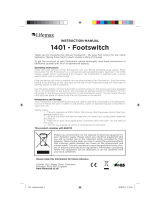
Footswitch, 255244
704
703
701
702
705
Ref Part Description Quantity
701 --- VALVE, vented 2 way 1
702 157350 ADAPTER 1
703 106148 FILTER, air, 3/8 NPT 1
704 155665 UNION, adapter 1
705 --- NIPPLE, pipe 1

Recommended Parts
16 334135B
Tanks
1 1/2 in. NPT Flanges, 24W417
8 Liter, Twin Polyethylene Tanks and Lids, 24W415
8 Liter, Twin Polyethylene Tanks and Lids, with Shut-Off Valves, 24W416
1008
1011
1008
1006
1005
1025
1007
1025
1007
1003
1003
1024
1005
1009
1023
1023
1020
1010
1002
1001
1018
1015
1019
1014
1001
1004

Recommended Parts
334135B 17
*Not Shown
Ref Part Description
Quantity
24W415 24W416 24W417
1001 95/0223/00 O-RING 2 4 1
1002 120901 O-RING 4 4
1003 120902 SCREW, M5x40mm 2 2
1004 120904 SCREW, M5x18mm 6 6 3
1005 120905 NUT, hex, lock M5 2 2
1006 120906 NUT, hex, lock M8 x 1.25 2 2
1007 120907 WASHER, plain #10 4 2
1008 120908 WASHER, plain M8 4 4
1009 120909 BREATHER 2 2
1010 120911 CLAMP, gap-free pinch hose 2 2
1011 120913 SCREW 2 2
1014 255280 VALVE, ball 2
1015 121013 SCREW, M5x25mm 6
1018 --- RING, lock 2 2
1019 --- FITTING, flange 2 2
1020 15K840 O-RING 2 2
1023 --- TANK, 8 liter 1 1
1024 15M226 BALLAST 1
15K842 BALLAST 1
1025 120915 CAP PLUG, square 2 2
1026* 15M237 FLANGE, 1-1/2 in. NPT 1

Recommended Parts
18 334135B
Hose Packages
Unheated, Non-Recirculating Hose
* High pressure hoses (3500 psi, 24 MPa, 241 bar)
Hose Package Description
Reference Number and Description
1401 1402 1403 1404
Hose Assembly 90 Deg Elbow Adapter Bushing
LC0801 3/16 in. x 30 in. 16C501 94/0144-S/25 94/1000/98 94/0488/98
LC0802 3/16 in. x 120 in. 16C506 94/0144-S/25 94/1000/98 94/0488/98
LC0803 3/16 in. x 180 in. 16C507 94/0144-S/25 94/1000/98 94/0488/98
LC0804 1/4 in. x 30 in. 16C510 94/0148-S/25 J6900040
LC0805 1/4 in. x 120 in. 16C515 94/0148-S/25 J6900040
LC0806 1/4 in. x 180 in. 16C516 94/0148-S/25 J6900040
LC0807 3/8 in. x 30 in. 16C519 94/0149-S/25 94/1007/98
LC0808 3/8 in. x 120 in. 16C524 94/0149-S/25 94/1007/98
LC0809 3/8 in. x 180 in. 16C525 94/0149-S/25 94/1007/98
LC0400* 3/8 in. x 30 in. 16D261 94/0149-S/25 94/1007/98
LC0401* 3/8 in. x 120 in. 16D266 94/0149-S/25 94/1007/98
LC0402* 3/8 in. x 180 in. 16D267 94/0149-S/25 94/1007/98
LC0810 1/2 in. x 30 in. 16C529 94/0150-S/25 94/1009/98
LC0811 1/2 in. x 120 in. 16C534 94/0150-S/25 94/1009/98
LC0812 1/2 in. x 180 in. 16C535 94/0150-S/25 94/1009/98
LC0403* 1/2 in. x 30 in. 16D271 94/0150-S/25 16C399
LC0404* 1/2 in. x 120 in. 16D276 94/0150-S/25 16C399
LC0405* 1/2 in. x 180 in. 16D277 94/0150-S/25 16C399
LC0813 3/4 in. x 120 in. 16C544 94/0153-S/25 94/1083/98
LC0814 3/4 in. x 180 in. 16C545 94/0153-S/25 94/1083/98
LC0406* 3/4 in. x 120 in. 16D286 94/0153-S/25 94/1083/98
LC0407* 3/4 in. x 180 in. 16D287 94/0153-S/25 94/1083/98
Quantity 1 1 11
1404
1403
1401
1402
Apply thread sealant tape to male npt threads before assembly.
1
Assembly LC0801 Shown
ti12446a

Recommended Parts
334135B 19

Recommended Parts
20 334135B
Piston Package
Nylon Piston, Stainless Steel Metering Tube Assemblies
Piston
Package
Reference Number and Description
601 602 603† 604 605 606
Tube,
pump
Nylon
Piston
Washer
Ring, support,
piston
Screw O-ring
LC1080 LCC080 LCB080
15M089
120933 120874
LC1100 LCC100 LCB100
LC1120 LCC120 LCB120
LC1140 LCC140 LCB140
LC1160 LCC160 LCB160
15M099
15K887
LC1180 LCC180 LCB180
LC1200 LCC200 LCB200
LC1220 LCC220 LCB220
LC1240 LCC240 LCB240
LC1260 LCC260 LCB260
LC1280 LCC280 LCB280
LC1300 LCC300 LCB300
15M100
LC1320 LCC320 LCB320
15K888
LC1360 LCC360 LCB360
LC1400 LCC400 LCB400
LC1440 LCC440 LCB440
LC1480 LCC480 LCB480
LC1520 LCC520 LCB520
LC1560 LCC560 LCB560
LC1600 LCC600 LCB600
LC1640 LCC640 LCB640
15K890
LC1720 LCC720 LCB720
15M101
LC1800 LCC800 LCB800
LC1880 LCC880 LCB880
LC1960 LCC960 LCB960
Quantity 1 1 1 1 1 2
606
601
606
605
603
602
604
ti12438a
Arrow on cylinder must point to the o-ring (606) on the right.
1
1
/