Page is loading ...

TMS320C6457 DSP
Host Port Interface (HPI)
User's Guide
Literature Number: SPRUGK7A
March 2009–Revised July 2010

2
SPRUGK7A–March 2009–Revised July 2010
Copyright © 2009–2010, Texas Instruments Incorporated

Preface ....................................................................................................................................... 6
1 Introduction to the HPI ......................................................................................................... 7
1.1 Summary of the HPI Registers ........................................................................................ 8
1.2 Summary of the HPI Signals ........................................................................................... 9
2 Using the Address Registers .............................................................................................. 11
2.1 Single-HPIA Mode ..................................................................................................... 11
2.2 Dual-HPIA Mode ....................................................................................................... 11
3 HPI Operation ................................................................................................................... 12
3.1 Host-HPI Signal Connections ........................................................................................ 12
3.2 HPI Configuration and Data Flow .................................................................................... 14
3.3 HDS2, HDS1, and HCS: Data Strobing and Chip Selection ..................................................... 15
3.4 HCNTL[1:0] and HR/W: Indicating the Cycle Type ................................................................ 16
3.5 HHWIL: Identifying the First and Second Halfwords in 16-Bit Multiplexed Mode ............................. 17
3.6 HAS: Forcing the HPI to Latch Control Information Early ........................................................ 17
3.7 Performing a Multiplexed Access Without HAS .................................................................... 20
3.8 Single-Halfword HPIC Cycle in the 16-Bit Multiplexed Mode .................................................... 22
3.9 Hardware Handshaking Using the HPI-Ready (HRDY) Signal .................................................. 22
4 Software Handshaking Using the HPI Ready (HRDY) Bit ........................................................ 29
4.1 Polling the HRDY Bit .................................................................................................. 29
5 Interrupts Between the Host and the CPU ............................................................................. 30
5.1 DSPINT Bit: Host-to-CPU Interrupts ................................................................................ 30
5.2 HINT Bit: CPU-to-Host Interrupts .................................................................................... 30
6 FIFOs and Bursting ............................................................................................................ 32
6.1 Read Bursting .......................................................................................................... 32
6.2 Write Bursting .......................................................................................................... 33
6.3 FIFO Flush Conditions ................................................................................................ 34
6.4 FIFO Behavior When a Hardware Reset or Software Reset Occurs ........................................... 34
7 Emulation and Reset Considerations ................................................................................... 35
7.1 Emulation Modes ...................................................................................................... 35
7.2 Software Reset Considerations ...................................................................................... 35
7.3 Hardware Reset Considerations ..................................................................................... 35
8 HPI Registers .................................................................................................................... 36
8.1 Introduction ............................................................................................................. 36
8.2 Power and Emulation Management Register (PWREMU_MGMT) .............................................. 37
8.3 Host Port Interface Control Register (HPIC) ....................................................................... 38
8.4 Host Port Interface Address Registers (HPIAW and HPIAR) .................................................... 40
8.5 Data Register (HPID) .................................................................................................. 41
Appendix A Revision History ...................................................................................................... 42
3
SPRUGK7A–March 2009–Revised July 2010 Table of Contents
Copyright © 2009–2010, Texas Instruments Incorporated

www.ti.com
List of Figures
1 HPI Position in the Host-DSP System ................................................................................... 7
2 Example of Host-DSP Signal Connections When Using the HAS Signal in the 32-Bit Multiplexed Mode .... 12
3 Example of Host-DSP Signal Connections When the HAS Signal is Tied High in the 32-Bit Multiplexed
Mode ........................................................................................................................ 13
4 Example of Host-DSP Signal Connections When Using the HAS Signal in the 16-Bit Multiplexed Mode .... 13
5 Example of Host-DSP Signal Connections When the HAS Signal is Tied High in the 16-Bit Multiplexed
Mode ........................................................................................................................ 14
6 HPI Strobe and Select Logic............................................................................................. 15
7 16-Bit Multiplexed Mode Host Read Cycle Using HAS .............................................................. 18
8 16-Bit Multiplexed Mode Host Write Cycle Using HAS .............................................................. 19
9 16-Bit Multiplexed Mode Host Read Cycle With HAS Tied High.................................................... 20
10 16-Bit Multiplexed Mode Host Write Cycle With HAS Tied High.................................................... 21
11 16-Bit Multiplexed Mode Single-Halfword HPIC Cycle with HAS Tied High....................................... 22
12 HRDY Behavior During an HPIC or HPIA Read Cycle in the 16-Bit Multiplexed Mode.......................... 23
13 HRDY Behavior During a Data Read Operation in the 16-Bit Multiplexed Mode (Case 1: HPIA Write
Cycle Followed by Nonautoincrement HPID Read Cycle) ........................................................... 23
14 HRDY Behavior During a Data Read Operation in the 16-Bit Multiplexed Mode (Case 2: HPIA Write
Cycle Followed by Autoincrement HPID Read Cycles) .............................................................. 23
15 HRDY Behavior During an HPIC Write Cycle in the 16-Bit Multiplexed Mode.................................... 24
16 HRDY Behavior During a Data Write Operation in the 16-Bit Multiplexed Mode (Case 1: No
Autoincrementing)......................................................................................................... 24
17 HRDY Behavior During a Data Write Operation in the 16-Bit Multiplexed Mode(Case 2: Autoincrementing
Selected, FIFO Empty Before Write).................................................................................... 24
18 HRDY Behavior During a Data Write Operation in the 16-Bit Multiplexed Mode(Case 3: Autoincrementing
Selected, FIFO Not Empty Before Write)............................................................................... 25
19 HRDY Behavior During an HPIC or HPIA Read Cycle in the 32-Bit Multiplexed Mode.......................... 25
20 HRDY Behavior During a Data Read Operation in the 16-Bit Multiplexed Mode (Case 1: HPIA Write
Cycle Followed by Nonautoincrement HPID Read Cycle) ........................................................... 26
21 HRDY Behavior During a Data Read Operation in the 32-Bit Multiplexed Mode (Case 2: HPIA Write
Cycle Followed by Autoincrement HPID Read Cycles) .............................................................. 26
22 HRDY Behavior During an HPIC Write Cycle in the 32-Bit Multiplexed Mode.................................... 27
23 HRDY Behavior During a Data Write Operation in the 32-Bit Multiplexed Mode (Case 1: No
Autoincrementing)......................................................................................................... 27
24 HRDY Behavior During a Data Write Operation in the 32-Bit Multiplexed Mode (Case 2:
Autoincrementing Selected, FIFO Empty Before Write).............................................................. 28
25 HRDY Behavior During a Data Write Operation in the 32-Bit Multiplexed Mode (Case 3:
Autoincrementing Selected, FIFO Not Empty Before Write)......................................................... 28
26 Host-to-CPU Interrupt State Diagram................................................................................... 30
27 CPU-to-Host Interrupt State Diagram................................................................................... 31
28 FIFOs in the HPI........................................................................................................... 32
29 Power and Emulation Management Register (PWREMU_MGMT) ................................................. 37
30 Host Access Permissions ................................................................................................ 38
31 CPU Access Permissions ................................................................................................ 38
32 Format of an Address Register (HPIAW or HPIAR) - Host Access Permissions ................................. 40
33 Format of an Address Register (HPIAW or HPIAR) - CPU Access Permissions ................................. 40
34 Data Register (HPID) (Host access permissions, CPU cannot access HPID) .................................... 41
4
List of Figures SPRUGK7A–March 2009–Revised July 2010
Copyright © 2009–2010, Texas Instruments Incorporated

www.ti.com
List of Tables
1 Summary of HPI Registers ................................................................................................ 9
2 HPI Signals .................................................................................................................. 9
3 Options for Connecting Host and HPI Data Strobe Pins............................................................. 15
4 Access Types Selectable by the HCNTL Signals..................................................................... 16
5 Cycle Types Selectable With the HCNTL and HR/W Signals ....................................................... 16
6 Host Port Interface (HPI) Registers..................................................................................... 36
7 Power and Emulation Management Register (PWREMU_MGMT) Field Descriptions........................... 37
8 Host Port Interface Control Register (HPIC) Field Descriptions..................................................... 38
9 Host Port Interface Address Registers (HPIAW or HPIAR) Field Descriptions ................................... 40
10 Data Register (HPID) Field Descriptions............................................................................... 41
11 TMS320C6457 HPI Revision History ................................................................................... 42
5
SPRUGK7A–March 2009–Revised July 2010 List of Tables
Copyright © 2009–2010, Texas Instruments Incorporated

Preface
SPRUGK7A–March 2009–Revised July 2010
Read This First
About This Manual
This guide describes the host port interface (HPI) on the TMS320C6457 digital signal processors (DSPs).
The HPI enables an external host processor (host) to directly access the internal or external memory of
the DSP using a 16-bit (HPI16) or 32-bit (HPI32) interface.
Notational Conventions
This document uses the following conventions.
• Hexadecimal numbers are shown with the suffix h. For example, the following number is 40
hexadecimal (decimal 64): 40h.
• Registers in this document are shown in figures and described in tables.
– Each register figure shows a rectangle divided into fields that represent the fields of the register.
Each field is labeled with its bit name, its beginning and ending bit numbers above, and its
read/write properties below. A legend explains the notation used for the properties.
– Reserved bits in a register figure designate a bit that is used for future device expansion.
Related Documentation From Texas Instruments
The following documents describe the C6000™ devices and related support tools. Copies of these
documents are available on the Internet at www.ti.com. Tip: Enter the literature number in the search box
provided at www.ti.com.
SPRU189 — TMS320C6000 DSP CPU and Instruction Set Reference Guide. Describes the CPU
architecture, pipeline, instruction set, and interrupts for the TMS320C6000 digital signal processors
(DSPs).
SPRU198 — TMS320C6000 Programmer's Guide. Describes ways to optimize C and assembly code for
the TMS320C6000™ DSPs and includes application program examples.
SPRU301 — TMS320C6000 Code Composer Studio Tutorial. Introduces the Code Composer Studio™
integrated development environment and software tools.
SPRU321 — Code Composer Studio Application Programming Interface Reference Guide.
Describes the Code Composer Studio™ application programming interface (API), which allows you
to program custom plug-ins for Code Composer.
SPRU871 — TMS320C64x+ Megamodule Reference Guide. Describes the TMS320C64x+ digital signal
processor (DSP) megamodule. Included is a discussion on the internal direct memory access
(IDMA) controller, the interrupt controller, the power-down controller, memory protection, bandwidth
management, and the memory and cache.
C6000, TMS320C6000, Code Composer Studio are trademarks of Texas Instruments.
All other trademarks are the property of their respective owners.
6
Preface SPRUGK7A–March 2009–Revised July 2010
Copyright © 2009–2010, Texas Instruments Incorporated

HPID
R/W FIFOs
HPIA
Increment
HPIC
Access
type
HD[31:0]/HD[15:0]
HDS1, HDS2
HR/W
HAS
HCNTL0
HCNTL1
(optional)
HINT
HRDY
HPI
Host
Data
Address
ALE
R/W
IRQ
Ready
HCS
Chip select
DSP
HPI DMA logic
HHWIL
(if needed)
Data strobes
Switched
central
resource
C64x+
megamodule
External
memory
I/F
Other
peripherals
EDMA3
Internal
memory
User's Guide
SPRUGK7A–March 2009–Revised July 2010
Host Port Interface (HPI)
This guide describes the host port interface (HPI) on the TMS320C6457 digital signal processors (DSPs).
The HPI enables an external host processor (host) to directly access DSP resources (including internal
and external memory) using a 16-bit (HPI16) or 32-bit (HPI32) interface.
1 Introduction to the HPI
The HPI provides a parallel port interface through which an external host processor (host) can access
DSP resources. The HPI enables a host device and CPU to exchange information via internal or external
memory. Dedicated address and data registers (HPIA and HPID respectively) within the HPI provide the
data path between the external host interface and the processor resources. An HPI control register (HPIC)
is available to the host and the CPU for various configuration and interrupt functions.
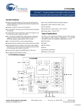
Figure 1 is a high-level block diagram showing how the HPI connects a host (left side of figure) and the
DSP internal resources (right side of figure). The host functions as a master to the HPI. Host activity is
asynchronous to the internal clock that drives the HPI. When HPI resources are temporarily busy or
unavailable, the HPI informs the host by deasserting the HPI-ready (HRDY) output signal.
Figure 1. HPI Position in the Host-DSP System
7
SPRUGK7A–March 2009–Revised July 2010 Host Port Interface (HPI)
Copyright © 2009–2010, Texas Instruments Incorporated

Introduction to the HPI
www.ti.com
The HPI uses multiplexed operation, meaning the data bus carries both address and data. When the host
drives an address on the bus, the address is stored in the address register (HPIA) in the HPI, so that the
bus can then be used for data.
The HPI supports two interface modes: HPI16 and HPI32 mode. DSP selects either HPI16 or HPI32 mode
via the HPI_WIDTH device configuration pin at reset.
• 16-bit multiplexed mode (HPI16). The HPI is called HPI16 when operating as a 16-bit wide host port.
This mode is selected if the HPI_WIDTH configuration pin of the DSP is sampled low at reset. In this
mode, a 16-bit data bus (HD[15:0]) carries both addresses and data. HPI16 combines successive
16-bit transfers to provide 32-bit data to the CPU. The halfword identification line (HHWIL) input is
used on the HPI16 to identify the first or second half word of a word transfer.
• 32-bit multiplexed mode (HPI32). HPI operates in this mode as a 32-bit wide host port. This mode is
selected if the HPI_WIDTH configuration pin of the DSP is sampled high at reset. In this mode, a 32-bit
data bus (HD[31:0]) carries both addresses and data. HHWIL is not applicable for HPI32 mode.
The HPI contains two HPIAs (HPIAR and HPIAW), which can be used as separate address registers for
read accesses and write accesses (for details, see Section 2).
A 32-bit control register (HPIC) is accessible by the DSP CPU and the host. The CPU can use HPIC to
send an interrupt request to the host, to clear an interrupt request from the host, and to monitor the HPI.
The host can use HPIC to configure and monitor the HPI, to send an interrupt request to the CPU, and to
clear an interrupt request from the CPU.
Data flow between the host and the HPI uses a temporary storage register, the 32-bit data register (HPID).
Data arriving from the host is held in HPID until the data can be stored elsewhere in the DSP. Data to be
sent to the host is held in HPID until the HPI is ready to perform the transfer. When address
autoincrementing is used, read and write FIFOs are used to store burst data. If autoincrementing is not
used, the FIFO memory acts as a single register (only one location is used).
NOTE: To manage data transfers between HPID and the internal memory, the DSP contains
dedicated HPI DMA logic. The HPI DMA logic is not programmable. It automatically stores or
fetches data using the address provided by the host. The HPI DMA logic is independent of
the EDMA3 controller included in the DSP.
In the DSP system, master and slave peripherals communicate with each other via the Switched Central
Resource (SCR). By definition, master peripherals are capable of initiating read and write transfers in the
system and may not solely rely on the EDMA3 controller for their data transfers. Slave peripherals rely on
the EDMA3 controller to perform transfers. The HPI is a master peripheral; it uses its DMA logic to directly
communicate with the rest of the system via the SCR and does not rely on the EDMA3 controller for its
data transfers. Note that the HPI cannot access all DSP resources or peripherals; see the device-specific
data manual for a list of resources accessible through the HPI.
1.1 Summary of the HPI Registers
Table 1 summarizes the registers inside the HPI, including access permissions and access requirements
from the perspective of the host and the DSP CPU. See Section 8 for detailed descriptions of all these
registers. Section 2 describes the two address registers (HPIAW and HPIAR) and describes the two HPIA
modes that determine how the host uses these registers.
The host can only access HPIC, HPIAW, HPIAR, and HPID. By driving specific levels on the HCNTL[1:0]
signals, the host indicates whether it is performing an HPIC, HPIA, or HPID access. For an HPID access,
the HCNTL signals also indicate whether or not the HPI should perform an automatic address increment
after the access. Section 3.4 describes the effects of the HCNTL[1:0] signals. The HR/W signal indicates
whether the host is reading or writing.
The DSP CPU cannot access HPID but has limited access to HPIC, HPIAR, and HPIAW. The CPU has
full access to the power and emulation management register, which selects an emulation mode for the
HPI.
HPI registers accessible by the CPU have an address in the DSP memory map. Table 1 shows the offset
addresses for various HPI registers. See the device-specific data manual for the base addresses of the
HPI registers.
8
Host Port Interface (HPI) SPRUGK7A–March 2009–Revised July 2010
Copyright © 2009–2010, Texas Instruments Incorporated

www.ti.com
Introduction to the HPI
Table 1. Summary of HPI Registers
Host Access CPU Access
Read/Write Access Requirements Read/Write Offset
Register Description Permissions Permissions Address
PWREMU_MGMT Power and Emulation None - Read/Write 04h
Management Register
HPIC Host Port Interface Control Read/Write HCNTL1 low Read: All bits 30h
Register HCNTL0 low Write: HINT
and DSPINT
bits only
HPIAW Host Port Interface Write Address Read/Write HCNTL1 high Read only 34h
Register HCNTL0 low
Single-HPIA mode, or
dual-HPIA mode with
HPIAW selected
(1)
HPIAR Host Port Interface Read Address Read/Write HCNTL1 high Read only 38h
Register HCNTL0 low
Single-HPIA mode, or
dual-HPIA mode with
HPIAR selected
(1)
HPID Host Port Interface Data Register Read/Write With autoincrementing: None None
HCNTL1 low
HCNTL0 high
No autoincrementing:
HCNTL1 high
HCNTL0 high
(1)
The single-HPIA mode and the dual-HPIA mode are described in Section 2.
1.2 Summary of the HPI Signals
Table 2 summarizes each of the HPI signals. It provides the signal name, the possible states for the signal
(input, output, or high-impedance), the connection(s) to be made on the host side of the interface, and a
description of the signal’s function.
CAUTION
Note that the encoding of HCNTL0 and HCNTL1 for the different types of HPI
accesses varies on many TI DSPs; therefore, you should use caution to ensure
that the correct encoding of these inputs is used for your device. The encoding
of these signals as described in this document applies only to C6457 DSPs.
Table 2. HPI Signals
Signal State
(1)
Host Connection Description
HCS I Chip select pin HPI chip select. HCS must be low for the HPI to be
selected by the host. HCS can be kept low between
accesses. HCS normally precedes an active HDS (data
strobe) signal, but can be connected to an HDS pin for
simultaneous select and strobe activity.
HDS1 and I Read strobe and write strobe pins or HPI data strobe pins. These pins are used for strobing
HDS2 any data strobe pin data in and out of the HPI (for data strobing details,
see Section 3.3). The direction of the data transfer
depends on the logic level of the HR/W signal.
The HDS signals are also used to latch control
information (if HAS is tied high) on the falling edge.
During an HPID write access, data is latched into the
HPID register on the rising edge of HDS. During read
operations, these pins act as output-enable pins of the
host data bus.
(1)
I = Input, O = Output, Z = High Impedance.
9
SPRUGK7A–March 2009–Revised July 2010 Host Port Interface (HPI)
Copyright © 2009–2010, Texas Instruments Incorporated

Introduction to the HPI
www.ti.com
Table 2. HPI Signals (continued)
Signal State
(1)
Host Connection Description
HCNTL[1:0] I Address or control pins The HPI latches the logic levels of these pins on the
falling edge of HAS or internal HSTRB (for details
about internal HSTRB, see Section 3.3). The four
binary states of these pins determine the access type
of the current transfer (HPIC, HPID with
autoincrementing, HPIA, or HPID without
autoincrementing).
HR/W I R/W strobe pin HPI read/write. On the falling edge of HAS or internal
HSTRB, HR/W indicates whether the current access is
to be a read or write operation. Driving HR/W high
indicates the transfer is a read from the HPI, while
driving HR/W low indicates a write to the HPI.
HHWIL I Address or control pins Halfword identification control input. This bit identifies
the first and second halfwords of a dual halfword cycle
operation. HHWIL=0 identifies the first cycle and
HHWIL=1 identifies the second cycle. HHWIL applies
only to HPI16 mode and not to HPI32 mode.
HAS I ALE (address latch enable) or Address strobe. A host with a multiplexed address/data
address strobe pin bus can have HAS connected to its ALE pin. The
falling edge of HAS latches the logic levels of the
HR/W, HCNTL1, and HCNTL0 pins, which are typically
connected to host address lines. When used, the HAS
signal must precede the falling edge of the internal
HSTRB signal.
HD[31:0] I/O/Z Data bus The HPI data bus carries the data to/from the HPI.
HD[15:0] HD[31:0] applies to HPI32 and HD[15:0] applies to
HPI16.
HRDY O/Z Asynchronous ready pin When the HPI drives HRDY low, the host has
permission to complete the current host cycle. When
the HPI drives HRDY high, the HPI is not ready for the
current host cycle to complete.
HINT O/Z Interrupt pin The DSP can interrupt the host processor by writing a
1 to the HINT bit of HPIC. Before subsequent HINT
interrupts can occur, the host must clear previous
interrupts by writing a 1 to the HINT bit. This pin is
active-low and inverted from the HINT bit value in
HPIC.
10
Host Port Interface (HPI) SPRUGK7A–March 2009–Revised July 2010
Copyright © 2009–2010, Texas Instruments Incorporated

www.ti.com
Using the Address Registers
2 Using the Address Registers
The HPI contains two 32-bit address registers: one for read operations (HPIAR) and one for write
operations (HPIAW). These roles are unchanging from the position of the HPI DMA logic. HPI DMA logic
collects the address from HPIAR when reading from DSP internal/external memory and collects the
address from HPIAW when writing to DSP internal/external memory.
However, unlike the HPI DMA logic, the host can choose how to interact with the two HPIA registers.
Using the DUALHPIA bit of HPIC, the host determines whether HPIAR and HPIAW act as a single 32-bit
register (single-HPIA mode) or as two independent 32-bit registers (dual-HPIA mode).
CAUTION
The host must always write a word address to the HPIAs. For example, L2
memory has a base byte address of 80 0000h that corresponds to a word
address of 20 0000h. A host must write 20 0000h to the HPIA register to point
the HPI to the base of L2 memory.
2.1 Single-HPIA Mode
If DUALHPIA = 0 in HPIC, HPIAR and HPIAW become a single HPIA register for the host. In this mode:
• A host HPIA write cycle (HCNTL[1:0] = 10b, HR/W = 0) updates HPIAR and HPIAW with the same
value.
• Both HPIA registers are incremented during autoincrement read/write cycles (HCNTL[1:0] = 01b).
• An HPIA read cycle (HCNTL[1:0] = 10b, HR/W = 1) returns the contents of HPIAR, which should be
identical to the contents of HPIAW.
To maintain consistency between the contents of HPIAR and HPIAW, the host should always re-initialize
the HPIA registers after changing the state of the DUALHPIA bit. In addition, when DUALHPIA = 0, the
host must always re-initialize the HPIA registers when it changes the data direction (from an HPID read
cycle to an HPID write cycle, or vice versa). Otherwise, the memory location accessed by the HPI DMA
logic might not be the host's intended location.
2.2 Dual-HPIA Mode
The host can take advantage of two independent HPIA registers by choosing the dual-HPIA mode
(DUALHPIA = 1 in HPIC). In this mode:
• A host HPIA access (HCNTL[1:0] = 10b) reads/updates either HPIAR or HPIAW, depending on the
value of the HPIA read/write select (HPIARWSEL) bit of HPIC. This bit is programmed by the host.
While HPIARWSEL = 1, only HPIAR is read or updated by the host. While HPIARWSEL = 0, only
HPIAW is read or updated by the host. The HPIARWSEL bit is only meaningful in the dual-HPIA mode.
NOTE: The HPIARWSEL bit does not affect the HPI DMA logic. Regardless of the value of
HPIARWSEL, the HPI DMA logic uses HPIAR when reading from memory and HPIAW when
writing to memory.
• A host HPID access with autoincrementing (HCNTL[1:0] = 01b) causes only the relevant HPIA value to
be incremented to the next consecutive memory address. In an autoincrement read cycle, HPIAR is
incremented after it has been used to perform the current read from memory. In an autoincrement write
cycle, HPIAW is incremented after it has been used for the write operation.
11
SPRUGK7A–March 2009–Revised July 2010 Host Port Interface (HPI)
Copyright © 2009–2010, Texas Instruments Incorporated

Address or I/O
Read/Write
Chip select
Data strobe
A
Data/address
Interrupt
Ready
HCNTL[1:0]
HR/W
HCS
HDS1
HDS2
HD[31:0]
HINT
HRDY
HPI
Host
Address latch enable HAS
No connect HHWIL
Logic high
2
32
DSP
HPI Operation
www.ti.com
3 HPI Operation
3.1 Host-HPI Signal Connections
Figure 2 and Figure 3 show examples of signal connections for the 32-bit multiplexed mode. Figure 4 and
Figure 5 show similar examples for the 16-bit multiplexed mode. In Figure 2 and Figure 4, the HAS signal
is used as described in Section 3.6. In Figure 3 and Figure 5, HAS is tied high (not used). Note the
following key comparisons between the signal connections in the two interface modes:
• The HPI_WIDTH configuration pin of the DSP must be held high at reset for the 32-bit multiplexed
mode (HPI32) or low at reset for the 16-bit multiplexed mode (HPI16).
• The address strobe (HAS) of the HPI is optional for both modes.
• The halfword identification control line (HHWIL) of the HPI is not used in the 32-bit multiplexed mode,
but is required in the 16-bit multiplexed mode.
CAUTION
Note that the encoding of HCNTL0 and HCNTL1 for the different types of HPI
accesses varies on many TI DSPs; therefore, you should use caution to ensure
that the correct encoding of these inputs is used for your device. The encoding
of these signals as described in this document applies only to C6457 DSPs.
Figure 2. Example of Host-DSP Signal Connections When Using the HAS Signal
in the 32-Bit Multiplexed Mode
A Data strobing options are given in Section 3.3.
12
Host Port Interface (HPI) SPRUGK7A–March 2009–Revised July 2010
Copyright © 2009–2010, Texas Instruments Incorporated

Address or I/O
Read/Write
Chip select
Data strobe
A
Data/address
Interrupt
Ready
HCNTL[1:0]
HR/W
HCS
HDS1
HDS2
HD[31:0]
HINT
HRDY
HPIHost
Logic high HAS
No connect HHWIL
Logic high
2
32
DSP
Read/Write
Chip select
Data strobe
A
Data/address
Interrupt
Ready
HCNTL[1:0]
HR/W
HCS
HDS1
HDS2
HD[15:0]
HINT
HRDY
HPI
DSP
Host
Address latch enable HAS
HHWIL
Logic
high
HD[31:16]
No
connect
2
16
16
www.ti.com
HPI Operation
Figure 3. Example of Host-DSP Signal Connections When the HAS Signal is Tied High
in the 32-Bit Multiplexed Mode
A Data strobing options are given in Section 3.3.
Figure 4. Example of Host-DSP Signal Connections When Using the HAS Signal
in the 16-Bit Multiplexed Mode
A Data strobing options are given in Section 3.3.
13
SPRUGK7A–March 2009–Revised July 2010 Host Port Interface (HPI)
Copyright © 2009–2010, Texas Instruments Incorporated

Read/Write
Chip select
Data strobe
A
Data
Interrupt
Ready
HCNTL[1:0]
HR/W
HCS
HDS1
HDS2
HD[15:0]
HINT
HRDY
HPI
DSP
Host
HAS
HHWIL
Logic high
Logic high
Address
or I/O
HD[31:16]No connect
2
16
16
HPI Operation
www.ti.com
Figure 5. Example of Host-DSP Signal Connections When the HAS Signal is Tied High in the 16-Bit
Multiplexed Mode
A Data strobing options are given in Section 3.3.
3.2 HPI Configuration and Data Flow
In multiplexed mode, the HPIC and HPIA must be initialized before valid host access cycles can take
place. The CPU and host must follow these steps to configure the HPI initially:
1. The CPU clears the HPIRST bit in the HPI register. All host accesses will be held off by the
deassertion of HRDY until HPIRST is cleared.
2. After the HPIRST bit is cleared, the host writes the HPIC register to program the halfword ordering bit
(HWOB) and the HPIA-related bits (DUALHPIA and HPIARWSEL). The HWOB bit must be
programmed before any accesses to the HPID and HPIA registers because this bit defines the
ordering of all halfword accesses in the 16-bit multiplexed mode.
3. The host writes the desired internal DSP word address to an address register (HPIAR and/or HPIAW).
Section 2 introduces the two HPIA registers and their interaction with the host.
4. The host either reads from or writes to the data register (HPID). Data transfers between HPID and the
internal resources of the DSP are handled by the HPI DMA logic.
Each step of the access uses the same bus. Therefore, the host must drive the appropriate levels on the
HCNTL1 and HCNTL0 signals to indicate which register is to be accessed. The host must also drive the
appropriate level on the HR/W signal to indicate the data direction (read or write) and must drive other
control signals as appropriate. When HPI resources are temporarily busy or unavailable, the HPI informs
the host by deasserting the HPI-ready (HRDY) output signal.
When performing an access, the HPI first latches the levels on HCNTL[1:0], HR/W, and other control
signals. This latching can occur on the falling edge of the internal strobe signal (see Section 3.3) or the
falling edge of HAS (see Section 3.6). After the control information is latched, the HPI initiates an access
based on the control signals.
14
Host Port Interface (HPI) SPRUGK7A–March 2009–Revised July 2010
Copyright © 2009–2010, Texas Instruments Incorporated

HDS1
HDS2
HCS
HRDY
Internal
HSTRB
Internal
HRDY
www.ti.com
HPI Operation
If the host wants to read data from the DSP internal/external memory, the HPI DMA logic reads the
memory address from HPIAR and retrieves the data from the addressed memory location. When the data
has been placed in HPID, the HPI drives the data onto its HD bus. The HRDY signal informs the host
whether the data on the HD bus is valid (HRDY low) or not valid yet (HRDY high). When the data is valid,
the host latches the data and drives the connected data strobe (HDS1 or HDS2) inactive, which, in turn,
will cause the internal strobe (internal HSTRB) signal to transition from low to high.
If the host wants to write data to the DSP internal/external memory, the operation is similar. After the host
determines that the HPI is ready to latch the data (HRDY is low), it must cause internal HSTRB to
transition from low to high, which causes the data to be latched into HPID. Once the data is in HPID, the
HPI DMA logic reads the memory address from HPIAW and transfers the data from HPID to the
addressed memory location.
3.3 HDS2, HDS1, and HCS: Data Strobing and Chip Selection
As illustrated in Figure 6, the strobing logic is a function of three key inputs: the chip select pin (HCS) and
two data strobe signals (HDS1 and HDS2). The internal strobe signal, which is referred to as internal
HSTRB throughout this document, functions as the actual strobe signal inside the HPI. HCS must be low
(HPI selected) during strobe activity on the HDS pins. If HCS remains high (HPI not selected), activity on
the HDS pins is ignored.
Figure 6. HPI Strobe and Select Logic
Strobe connections between the host and the HPI partially depend on the number and types of strobe pins
available on the host. Table 3 describes various options for connecting to the HDS pins. Notice in Figure 6
that HRDY is also gated by HCS. If HCS goes high (HPI not selected), HRDY goes low, regardless of
whether the current internal transfer is completed in the DSP.
Table 3. Options for Connecting Host and HPI Data Strobe Pins
Available Host Data Strobe Pins Connections to HPI Data Strobe Pins
Host has separate read and write strobe Connect one strobe pin to HDS1 and other to HDS2
(1)
. Because such a host might not
pins, both active-low provide an R/W line, HR/W timings must be satisfied as stated in the device datasheet,
perhaps by using a host address line.
Host has separate read and write strobe Connect one strobe pin to HDS1 and other to HDS2
(1)
. Because such a host might not
pins, both active-high provide an R/W line, HR/W timings must be satisfied as stated in the device datasheet,
perhaps by using a host address line.
Host has one active-low strobe pin Connect the strobe pin to HDS1 or HDS2, and connect the other pin to logic level 1.
Host has one active-high strobe pin Connect the strobe pin to HDS1 or HDS2, and connect the other pin to logic level 0.
(1)
The HR/W signal could be driven by a host address line in this case.
NOTE:
1. The HCS input and one HDS strobe input can be tied together and driven with a single
strobe signal from the host. This technique selects the HPI and provides the strobe
simultaneously. When using this method, note that HRDY is gated by HCS as previously
described.
2. It is not recommended to tie both HDS1 and HDS2 to static logic levels and use HCS as
a strobe.
15
SPRUGK7A–March 2009–Revised July 2010 Host Port Interface (HPI)
Copyright © 2009–2010, Texas Instruments Incorporated

HPI Operation
www.ti.com
3.4 HCNTL[1:0] and HR/W: Indicating the Cycle Type
The cycle type consists of:
• The access type selected by the host by driving the appropriate levels on the HCNTL[1:0] pins of the
HPI. Table 4 describes the four available access types.
• The transfer direction that the host selects with the HR/W pin. The host must drive the HR/W signal
high (read) or low (write).
Table 5 summarizes the cycle types. The HPI samples the HCNTL levels either at the falling edge of HAS
(if HAS is used) or at the falling edge of the internal strobe signal HSTRB (if HAS is not used or is tied
high).
CAUTION
Note that the encoding of HCNTL0 and HCNTL1 for the different types of HPI
accesses varies on many TI DSPs; therefore, you should use caution to ensure
that the correct encoding of these inputs is used for your device. The encoding
of these signals as described in this document applies only to C6457 DSPs.
Table 4. Access Types Selectable by the HCNTL Signals
HCNTL1 HCNTL0 Description
0 0 HPIC access. The host requests to access the HPI control register
(HPIC).
0 1 HPID access with autoincrementing. The host requests to access the
HPI data register (HPID) and to have the appropriate HPI address
register (HPIAR and/or HPIAW) automatically incremented by 1 after
the access.
1 0 HPIA access. The host requests to access the appropriate HPI
address register (HPIAR and/or HPIAW).
1 1 HPID access without autoincrementing. The host requests to access
the HPI data register (HPID) but requests no automatic
post-increment of the HPI address register.
Table 5. Cycle Types Selectable With the HCNTL and HR/W Signals
HCNTL1 HCNTL0 HR/W Cycle Type
0 0 0 HPIC write cycle
0 0 1 HPIC read cycle
0 1 0 HPID write cycle with autoincrementing
0 1 1 HPID read cycle with autoincrementing
1 0 0 HPIA write cycle
1 0 1 HPIA read cycle
1 1 0 HPID write cycle without
autoincrementing
1 1 1 HPID read cycle without
autoincrementing
16
Host Port Interface (HPI) SPRUGK7A–March 2009–Revised July 2010
Copyright © 2009–2010, Texas Instruments Incorporated

www.ti.com
HPI Operation
3.5 HHWIL: Identifying the First and Second Halfwords in 16-Bit Multiplexed Mode
In the 16-bit multiplexed mode, each host cycle consists of two consecutive halfword transfers. For each
transfer, the host must specify the cycle type with HCNTL[1:0] and HR/W, and the host must use HHWIL
to indicate whether the first or second halfword is being transferred. For HPID and HPIA accesses, HHWIL
must always be driven low for the first halfword transfer and high for the second halfword transfer. Results
are undefined if the sequence is broken. For examples of HHWIL usage, see the figures in Section 3.6
and Section 3.7.
When the host sends the two halfwords of a 32-bit word in this manner, the host can send the most and
least significant halfwords of the 32-bit word in either order (most significant halfword first or most
significant halfword second). However, the host must inform the HPI of the selected order before
beginning the host cycle. This is done by programming the halfword order (HWOB) bit of HPIC. Although
(HWOB) is written at bit 0 in HPIC, its current value is readable at both bit 0 and bit 8 (HWOBSTAT).
Thus, the host can determine the current halfword-order configuration by checking the least significant bit
of either half of HPIC.
There is one case when the 16-bit multiplexed mode does not require a dual-halfword cycle with HHWIL
low for the first halfword and HHWIL high for the second halfword. The least significant 16 bits of the HPIC
register can be accessed with a single-halfword cycle. During such a cycle, the host can drive HHWIL
either high or low. Either approach returns the same value. Section 3.9 includes an example timing
diagram of this case.
In the 32-bit multiplexed mode, each host cycle is one word transfer. The HHWIL signal is ignored and 32
bits of data transferred for each active cycle of the internal strobe signal (internal HSTRB).
3.6 HAS: Forcing the HPI to Latch Control Information Early
The HAS signal is an address strobe that allows control information to be removed earlier in a host cycle,
allowing more time to switch bus states from address to data information. This feature facilitates the
interface for multiplexed address and data buses. In this type of system, an address latch enable (ALE)
signal is often provided and is normally the signal connected to HAS.
Figure 2 and Figure 4 show examples of signal connections when HAS is used for multiplexed transfers.
Figure 7 and Figure 8 show typical HPI signal activity when HAS is used. The process for using HAS is as
follows:
1. The host selects the access type. The host drives the appropriate levels on the HCNTL [1:0] and HR/W
signals, and indicates which halfword (first or second) will be transferred by driving HHWIL high or low.
2. The host drives HAS low. On the falling edge of HAS, the HPI latches the states of the HCNTL[1:0],
HR/W, and HHWIL. The high to low transition of HAS must precede the falling edge of the internal
strobe signal (internal HSTRB), which is derived from HCS, HDS1, and HDS2, as described in
Section 3.3.
HCS does not gate the HAS input, which allows time for the host to perform the subsequent access. The
HAS signal may be brought high after internal HSTRB goes low, indicating that the data access is about to
occur. HAS is not required to be driven high at any time during the cycle, but eventually must transition
high before the host uses it for another access with different values for HCNTL [1:0], HR/W, and HHWIL.
17
SPRUGK7A–March 2009–Revised July 2010 Host Port Interface (HPI)
Copyright © 2009–2010, Texas Instruments Incorporated

Data 2Data 1
HCS
HAS
HSTRB
HR/W
HCNTL[1:0]
HD[15:0]
HRDY
A
HHWIL
Internal
HPI latches
control information
Host latches
data
HPI latches
control information
Host latches
data
HPI Operation
www.ti.com
Figure 7. 16-Bit Multiplexed Mode Host Read Cycle Using HAS
A Depending on the type of write operation (HPID without autoincrementing, HPIA, HPIC, or HPID with
autoincrementing) and the state of the FIFO, transitions on HRDY may or may not occur. For more information, see
Section 3.9.
18
Host Port Interface (HPI) SPRUGK7A–March 2009–Revised July 2010
Copyright © 2009–2010, Texas Instruments Incorporated

HCS
HAS
HSTRB
HR/W
HCNTL[1:0]
HRDY
A
HHWIL
Data 1 Data 2
HD[15:0]
Internal
HPI latches
control information
HPI latches
data
HPI latches
control information
HPI latches
data
www.ti.com
HPI Operation
Figure 8. 16-Bit Multiplexed Mode Host Write Cycle Using HAS
A Depending on the type of write operation (HPID without autoincrementing, HPIA, HPIC, or HPID with
autoincrementing) and the state of the FIFO, transitions on HRDY may or may not occur. For more information, see
Section 3.9.
19
SPRUGK7A–March 2009–Revised July 2010 Host Port Interface (HPI)
Copyright © 2009–2010, Texas Instruments Incorporated

Data 2Data 1
HCS
HSTRB
HR/W
HCNTL[1:0]
HD[15:0]
HRDY
A
HHWIL
Internal
HPI latches
control information
Host latches
data
HPI latches
control information
Host latches
data
HPI Operation
www.ti.com
3.7 Performing a Multiplexed Access Without HAS
The HAS signal is not required when the host processor has dedicated signals (address lines or bit I/O)
capable of driving the control lines. Dedicated pins can be directly connected to HCNTL[1:0], HR/W, and
HHWIL.
Figure 3 and Figure 5 show examples of signal connections when HAS is not used for multiplexed
transfers. When HAS is not used, it must be tied high (inactive). Figure 9 and Figure 10 show typical HPI
signal activity when HAS is tied high. The falling edge of internal HSTRB latches the HCNTL[1:0], HR/W,
and HHWIL states into the HPI. Internal HSTRB is derived from HCS, HDS1, and HDS2, as described in
Section 3.3.
Figure 9. 16-Bit Multiplexed Mode Host Read Cycle With HAS Tied High
A Depending on the type of write operation (HPID without autoincrementing, HPIA, HPIC, or HPID with
autoincrementing) and the state of the FIFO, transitions on HRDY may or may not occur. For more information, see
Section 3.9.
20
Host Port Interface (HPI) SPRUGK7A–March 2009–Revised July 2010
Copyright © 2009–2010, Texas Instruments Incorporated
1/43