Page is loading ...

THANK YOU
We appreciate the trust and confidence you have placed in Hampton Bay through the purchase of this bookcase. We strive to continually create
quality products designed to enhance your home. Visit us online to see our full line of products available for your home improvement needs.
Thank you for choosing Hampton Bay!
USE AND CARE GUIDE
Elite 3 Drawer Base Unit - White
Questions, problems, missing parts? Before returning to the store,
call Hampton Bay Customer Service
8 a.m. - 6 p.m., EST, Monday - Friday
1-855-HD-HAMPTON
HAMPTONBAY.COM
OMSID # 205703222
Model # THD171007.1a

2
Table of Contents
Table of Contents ...................................2
Safety Information ..................................2
Warranty ..........................................2
Pre-Assembly ......................................
......................................
......................................
......................................
......................................
......................................
......................................
3
Planning Assembly
Tools Required
Hardware Included
Package Contents
Assembly
Weight Limits
3
3
3
4
5
11
Safety Information
Read and understand all instructions before assembly.
Warranty
LIMITED ONE YEAR PRODUCT WARRANTY
WHAT IS COVERED
This limited warranty covers the original purchase of this product used for normal commercial,
Personal, or household use. The supplier warrants its products will be free from defects in materials and workmanship (normal wear and
tear excepted) for a period of one (1) year from the date of purchase, except as provided below. The supplier, at its option, will replace with
a comparable product, free of charge, any product purchased from it that fails under normal use as a result of such defect.
Materials are warranted for one year from date of purchase. Proof of purchase is required in the form of a receipt (copy or original) to
validate the warranty.
The supplier provides this limited warranty in lieu of all other warranties either expressed or implied. Expressly excluded are all warranties
shall be limited to the repair, refund or replacement at the supplier’s sole discretion and cost, of product or components.
THIS WARRANTY APPLIES ONLY TO THE U.S. AND CANADA.
WHAT IS NOT COVERED
improper cleaning or other circumstances not directly attributable to defects in materials and workmanship.
Natural variations occurring in wood or other materials will not be considered defects, and the supplier does not warrant the color-fastness
the product not approved, and products that were not installed, used, or maintained in accordance with product instructions and warnings.
Contact the Customer Service Team at 1-855-HD-HAMPTON or visit www.Hamptonbay.com.

3
HAMPTONBAY.COM
Please contact 1-855-HD-HAMPTON for further assistance.
Pre-Assembly
PLANNING ASSEMBLY
Compare all parts with the Hardware Included and Package Contents lists in this manual. If any part appears missing or damaged, do not
assemble this product. Contact the Customer Service Team at 1-855-HD-HAMPTON or visit www.HamptonBay.com.
TOOLS REQUIRED
Flathead
screwdriver
Phillips
screwdriver
HARDWARE INCLUDED
NOTE: Hardware not shown to actual size.
Part Description Quantity
a
a
a
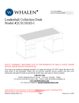
How to Disconnect Cabinet and Drawer members of Ball Bearing slide.
Pull toward arrow to open the slide until its stops and then flip it over.
Push plastic lever down and pull apart
Cabinet member
Drawer member
16
28
20
12
6
3
24
16
12
12
Cam Lock
Cam Bolt
Wood Dowel
Small Cam Lock
Bolt
Knob
3.5*14 mm Screw
3*12 mm Screw
4*35 mm Screw
3*14 mm Screw
Left Cabinet Rail
Left Drawer Slide
Right Cabinet Rail
Right Drawer Slide
Cabinet member
Drawer member
Small Wood Dowel
b
c
d
e
f
g
h
i
j
f
g
q
p
p
q
b c hd e
l
m
n
o
left cabinet rail
Cabinet member Drawer member
left drawer slide
right drawer slideright cabinet rail
22
1
k
l
1
1
1
4
4
m
n
o
p
q
j
k
i

4
Pre-Assembly (continued)
PACKAGE CONTENTS
Part Description Quantity
A Top 1
B1
C
Bottom
1
D
Left Side Panel
1
E1
F2
Right Side Panel
Bottom Front Rail
Cross Bars
A
C
D
E
B
F
F
G
H
I
J
K
L
M
M
N
N
O
O
P
P
Q
Q
G1
H1
Back Panel
Small Drawer Front
I1
Small Left Drawer Side
Large Drawer Front
Large Left Drawer Side
Part Description Quantity
J Small Right Drawer Side 1
K1
L
Small Drawer Back
1
M
Small Drawer Bottom
Large Right Drawer Side
Large Drawer Back
Large Drawer Bottom
2
N2
O2
P2
Q2

5
HAMPTONBAY.COM
Please contact 1-855-HD-HAMPTON for further assistance.
Assembly
1
Preparing the top and two cross bars
□ Insert twelve wood dowels (c) into the top (A) and two
cross bars (F).
c
2
Assembling the bottom and bottom
front rail
□ Insert eight wood dowels (c) into the bottom (B) and
bottom front rail (E).
□ Turn two cam bolts (b) into the holes in the bottom (B).
□ Connection bottom (B) and bottom front rail (E) , ensure that the
wood dowels (c) and cam bolts (b) are fully inserted into the
appropriate holes.
□ Insert two cam locks (a) into the attached holes to the bottom front
rail (E) , then turn all of the cam lock (a) clockwise until they lock into
place over the cam bolts (b).
A
B
B
F
F
E
E
c
b
a
b
c
c
c

6
Assembly (continued)
3
Assembling the slides to the left side panel
□ Turn seven cam bolts (b) into the holes in the left side panel (C).
□ fasten the left cabinet rail (l) and two cabinet members (p) to the left side panel (C) ,
Use nine screws (g) into the exact holes shown in the enlarged diagrams.
C
C
Open end
Open end
Roller end
p
g
Roller end
l
b
g

7
Assembly (continued)
4
Assembling the slides to the right side panel
□ Turn seven cam bolts (b) into the holes in the right side panel (D).
□ fasten the right cabinet rail (n) and two cabinet members (p) to the right side panel (D) ,
Use nine screws (g) into the exact holes shown in the enlarged diagrams.
D
D
HAMPTONBAY.COM
Please contact 1-855-HD-HAMPTON for further assistance.
Open end
Roller end
Roller end
Open end
p
n
g
g
b

8
Assembly (continued)
5
Assembling the right side panel
□ Connection top (A) , two cross bars (F) , bottom (B) , bottom front rail (E) , and
right side panel (D) , ensure that the wood dowels (c) and cam bolts (b) are fully
inserted into the appropriate holes.
□ Insert seven cam locks (a) into the holes to the top (A) ,
two cross bars (F) , bottom (B) , bottom front rail (E) , then turn
all of the cam lock (a) clockwise until they lock into
place over the cam bolts (b).
6
Assembling the left side panel
□ Connection top (A) , two cross bars (F) , bottom (B) , bottom front rail (E) , and
left side panel (C) , ensure that the wood dowels (c) and cam bolts (b) are fully
inserted into the appropriate holes.
□ Insert seven cam locks (a) into the holes to the top (A) ,
two cross bars (F) , bottom (B) , bottom front rail (E) , then turn
all of the cam lock (a) clockwise until they lock into
place over the cam bolts (b).
C
D
A
A
B
B
D
F
E
F
F
F
E
a
c
a
b
Unfinished edge
Unfinished edge
Unfinished edge

9
Assembly (continued)
7
Assembling the back panel
□ Fasten the back panels (G) to the assembled unit using twenty-two screws (k) ,
Do not over tighten the screws.
8
Assembling the drawer front
□ Turn four cam bolt (b) into the holes in the small drawer front (H).
□ Turn eight cam bolt (b) into the holes in the two large drawer fronts (M).
HAMPTONBAY.COM
Please contact 1-855-HD-HAMPTON for further assistance.
B
H
M
M
G
C
Before attaching the back panel be sure
that the unit is at 90°
k
b
b
b

10
Assembly (continued)
9
Assembling the drawer menber
□ insert sixteen small wood dowels (h) into the two large drawer sides (N and O) and two large drawer backs (p).
□ Fasten the four drawers member (q) to the large drawer sides (N and O) , use twelve screws (i) into the exact holes shown in the enlarged diagram.
P
P
N
N
O
O
h
q
h
h
h
h
h

11
Assembly (continued)
10
Assembling the large drawer
□ Fasten the large drawer sides (N and O) to the large drawer back (P) , Use four 35mm screws (j) , be sure the small
wood dowels in the large drawer back inserts into the holes in the large drawer sides.
□ Slide the large drawer bottom (Q) into the grooves in the large drawer sides (N and O) and large drawer back (P).
□ Insert four small cam locks (d) into the large drawer sides (N and O) , be sure the wood dowels in the large drawer sides
insert into the holes in the large drawer front , fasten the large drawer front (M) to the large drawer sides (N and O) ,
tighten four small cam lock.
□ Fasten a knob (f) to the large drawer front (M) , use two bolts (e).
□ The same assembling step for the other large drawer.
HAMPTONBAY.COM
Please contact 1-855-HD-HAMPTON for further assistance.
P
P
Q
N
N
M
O
O
d
f
e

12
Assembly (continued)
11
Assembling the small drawer
□ Fasten the small drawer sides (I and J) to the small drawer back (K) , Use four 35mm screws (j).
□ Slide the small drawer bottom (L) into the grooves in the small drawer sides (I and J) and small drawer back (K).
□ Insert four small cam locks (d) into the small drawer sides (I and J) , fasten the small drawer front (H) to the small
drawer sides (I and J) , tighten four small cam lock.
□ Fasten a knob (f) to the small drawer front (H) , use two bolts (e).
□ Fasten the left drawer slide (m) and right drawer slides (o) to the small drawer
side panel (I and J) , use six screws (g) through the exact holes shown in the
enlarged diagram.
H
H
J
J
J
K
K
I
I
L
L
j
m
g
g
o
d
f
e

12
Put the drawer into the cabinet
□ To insert the large drawer into your unit, line up the extension slides on the drawer with the extension rails on the unit and push the drawer into
the unit until the drawer is fully inserted. the drawer will push in hard until it is all the way in, then it will slide in and out easier , repeat this step
for the other large drawer.
□ To insert the remaining drawer into your unit , tip the front of the drawer down and drop the rollers on the drawer behind the rollers on the unit ,
lift the front of the drawer up and slide it into the unit.
□ To make adjustments to the drawers , loosen the screws in the slotted
holes, make needed adjustments, and tighten the screws.
13
Assembly (continued)
HAMPTONBAY.COM
Please contact 1-855-HD-HAMPTON for further assistance.
NOTE : If needed to remove drawer, pull the drawer fully
open so levers are visible , push up on left side lever and
down on right side lever , holding levers in place, pull
drawer toward you.
M
M
H

14
Assembly (continued)
WEIGHT LIMITS
□ This unit has been designed to support the maximum loads shown.
Exceeding these load limits could cause sagging, instability,
product collapse, and/or serious injury.
WARNING: Please ensure that all the objects are removed
before moving the assembled unit. The unit must be lifted
by more than one person, not dragged or pushed. Failure
to do so will cause product damage, instability, product
collapse, and/or serious injury.
30 lbs
20 lbs
20 lbs
15 lbs

Questions, problems, missing parts? Before returning to the store,
call Hampton Bay Customer Service
8 a.m.-6 p.m., EST, Monday-Friday
1-855-HD-HAMPTON
HAMPTONBAY.COM
Retain this manual for future use.
/