IMPORTANT NOTES:
• We suggest that shower compartments be equipped with support handrails that comply with
ANSI-A117.1-1986 Consumer Safety requirements
• SHOWERTUB™ IS NOT TO BE INSTALLED IN FRONT OF DRYWALL!
• Thoroughly READ and UNDERSTAND instructions before beginning installation of your MUSTEE ShowerTub™
CAREGIVER®/SHOWERTUB™ INSTALLATION
The ShowerTub™ is designed to be drained by 2” nominal pipe, connected to a trapped/vented sanitary waste
line. Refer to “Rough-In Dimensions” for proper placement and drain center lines.
Two MUSTEE Drain Assemblies are available for this installation:
PN-42.317A for sch.40 ABS, PVC or Iron pipe with drain seal connection
PN-42.304A for sch.40 PVC solvent welded connection
Both drain assemblies are IAPMO®/UPC® listed, file no. 1635.
If the ShowerTub™ is replacing an existing bathtub with 1-1/2” pipe connection, you have two (2) options --- the
first being to increase the existing lines to 2” DWV or soil pipe, --- the second being to use the MUSTEE
ShowerTub™ 1-1/2” Drain Kit Part No. 60.300. Before choosing either option, check to be sure that you are in full
compliance with local code regulations.
SI-199 (5•06)SI-199 (5•06)
“ROUGH-IN” DIMENSIONS
SHOWERTUB™
Quality Plumbing Products
E.L. MUSTEE & SONS, INC.
5431 West 164th Street • Brook Park, Ohio 44142
U.S. PATENT PENDING
LISTED
FILE
NO. 1453
• FITS INTO STANDARD 5 FT. BATHTUB ALCOVE •
CARE & CLEANING
The surface of your ShowerTub™ may be cleaned with a mild soap solution in warm water using a soft
cloth. For stubborn stains use “Soft Scrub” by Clorox or Lysol “Tub and Tile Cleaner” or a powdered
detergent such as “Spic-n-Span”. Never use an abrasive scouring powder or steel wool pads as they will
dull the surface. A periodic coating of a silicone based marine polish will help retain the fine finish.
FINISHED WALL DETAIL
Complete installation by finishing alcove walls using “FINISHED WALL DETAIL” as a reference.
ACCESSORIES (ORDER SEPARATELY)
ShowerTub™ Drain Kit - Part No. 60.300
The quick, convenient way to replace the Previous
tub waste and connect ShowerTub™ to existing
1-1/2” pipe. Complete kit includes easy to follow
installation instructions.
Pull-Down Shower Seats - Strong, durable, white
pull-down seats made with 18-gauge stainless steel
tubing (satin finish) and comfortably padded with
non-corded edges. Available for either right or left
side installations.
Part No. Size Type
390.401 26” Right
390.402 26” Left
ShowerTub™ Drain Adaptor Kit
Part No. 60.306A “White”
Part No. 60.307A “Bone”
A unique component that allows the standard drain
hole outlet on the ShowerTub™ to accept Part No.
60.300 Drain Kit. Complete kit includes easy to
follow installation instructions. U.S. Patent Pending
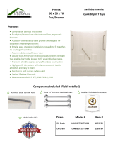
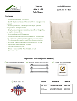
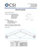
Stainless Steel Grab Bars - Straight and inside
corner (L-shape) grab bars are concealed-flange
type and made with tough 18-gauge 1-1/2”
diameter stainless steel tubing, satin finish.
Part No. Size Type
390.301 24” Straight
390.302 48” Straight
390.303 20”x42” L-shape
E.L. MUSTEE & SONS, INC.
5431 West 164th Street • Brook Park, Ohio 44142
INSTALLATION INSTRUCTIONS

SI-199 (5•06) SI-199 (5•06)
The size and style of drain must be determined before installation of the ShowerTub™ can begin. Both 2” Drain
Assemblies require a 5” (inch) square hole in the sub-floor or slab, centered around the sanitary waste pipe.
The drain body for either PN 42.317A or PN 42.304A must be assembled to the ShowerTub™ before installing
into the alcove (the drain body is secured with a locknut on the underside of the floor area.) Be sure to use all
washers that are supplied with the drain assembly, refer to “TYPICAL DRAIN CONNECTION” for reference.
The MUSTEE ShowerTub™ 1-1/2” Drain Kit may be installed after placement into the alcove area (with access
to the underside of the unit). Complete installation instructions are furnished with kit.
NEW CONSTRUCTION
The ShowerTub™ must not be installed on exposed floor joists, if there is no sub-floor at the desired
location, a one piece section of CDX sheathing - minimum 3/4” thick, must be securely fastened to the floor
joists so that the ShowerTub™ is fully supported. HINT: To reduce creaking or squeaks we suggest that
“deck” type screws (3” min. length) along with adhesive be used to secure the sub-floor to the floor joists.
REMODELING
Remove existing bathtub from alcove, inspect condition of sub-floor for damage, if necessary, replace
existing sub-floor with CDX sheathing as described under NEW CONSTRUCTION.
A. For either NEW CONSTRUCTION or REMODELING, while a mortar bed is not required for structural
support, a thin layer will aid in the leveling of the ShowerTub™ and help ensure that all ribs are fully
supported.
B. If you choose not to use mortar, a layer of 30 lb. roofing felt (or equivalent) should be used to compensate
for any minor inconsistencies in the sub-floor or slab.
C. Set ShowerTub™ into alcove, making sure that it is properly level. Check level on to edge of tile flange only
- all other surfaces are tapered.
D. Make final drain and supply connections as previously determined.
TYPICAL DRAIN CONNECTION
CAUTION: DO NOT USE ANY PUTTY OR THREAD SEALING COMPOUND UNDER FLANGE OR ON
THREADS OF DRAIN BODY - FAILURE AND LEAKAGE MAY RESULT!! DO NOT OVERTIGHTEN LOCKNUT -
HAND TIGHTEN, THEN WRENCH AN ADDITIONAL 3/4 TURN - MAXIMUM.
To use the MUSTEE MODEL NO. 3060 ShowerTub™ with existing 1-1/2” plumbing, we have designed an
adaptor that will reduce the standard drain hole outlet to accept Part No. 60.300 “ShowerTub™ Drain Kit”.
Proceed as follows:
1. Stand and secure the ShowerTub™ on end with drain hole up - this will make installation of the Drain
Adaptor - PN 60.306 easier.
2. Apply a small bead (approximately 1/8” diameter) of siliconized sealant (not furnished) to the underside of
the drain adaptor top flange, as shown in (FIG. 1).
3. Insert adaptor into drain hole, holding adaptor from moving (from the underside of the Showertub™) first
apply the 1/8” Sealing Washer - PN 42.319 followed by the Friction Washer - PN 32.207 and secure in place
with Locknut - PN 42.305.
4. DO NOT overtighten locknut - pull up snug then wrench an additional 1/4 turn. Wipe away any excess
sealant that seeps out around the top flange of the adaptor on the inside of the ShowerTub™.
5. Attach Part No. 60.300 ShowerTub™ Drain Kit to complete installation.
ShowerTub™ Drain Kit
Part No. 60.300
STRAINER RETAINING SCREW
STRAINER
DRAIN BODY
SEALING WASHER
DRAIN ELL & TUBE
BUSHING FOR 1-1/2” TUBULAR PIPE (2)
1-1/2” 90
O
RUBBER ELBOW
7
6
5
4
3
2
1
2 3
U.S. PATENT PENDING
DRAIN
ADAPTOR
ASSEMBLY
Ref: Drain Adaptor Ass’y - PN 60.307A (Bone)
Drain Adaptor Ass’y - PN 60.306A (White)
*AN OPTIONAL DRAIN SEAL:
PN 42.320, IS AVAILABLE FOR 2” COPPER (DWV)
PN 42.321, IS AVAILABLE FOR 2” SOIL PIPE (SW) NO-HUB
(SOLD SEPARATELY)
42.317A (2” DRAIN W/SEAL)
42.304A (2” SOLVENT WELD)

IMPORTANT NOTES:
• We suggest that shower compartments be equipped with support handrails that comply with
ANSI-A117.1-1986 Consumer Safety requirements
• SHOWERTUB™ IS NOT TO BE INSTALLED IN FRONT OF DRYWALL!
• Thoroughly READ and UNDERSTAND instructions before beginning installation of your MUSTEE ShowerTub™
CAREGIVER®/SHOWERTUB™ INSTALLATION
The ShowerTub™ is designed to be drained by 2” nominal pipe, connected to a trapped/vented sanitary waste
line. Refer to “Rough-In Dimensions” for proper placement and drain center lines.
Two MUSTEE Drain Assemblies are available for this installation:
PN-42.317A for sch.40 ABS, PVC or Iron pipe with drain seal connection
PN-42.304A for sch.40 PVC solvent welded connection
Both drain assemblies are IAPMO®/UPC® listed, file no. 1635.
If the ShowerTub™ is replacing an existing bathtub with 1-1/2” pipe connection, you have two (2) options --- the
first being to increase the existing lines to 2” DWV or soil pipe, --- the second being to use the MUSTEE
ShowerTub™ 1-1/2” Drain Kit Part No. 60.300. Before choosing either option, check to be sure that you are in full
compliance with local code regulations.
SI-199 (5•06)SI-199 (5•06)
“ROUGH-IN” DIMENSIONS
SHOWERTUB™
Quality Plumbing Products
E.L. MUSTEE & SONS, INC.
5431 West 164th Street • Brook Park, Ohio 44142
U.S. PATENT PENDING
LISTED
FILE
NO. 1453
• FITS INTO STANDARD 5 FT. BATHTUB ALCOVE •
CARE & CLEANING
The surface of your ShowerTub™ may be cleaned with a mild soap solution in warm water using a soft
cloth. For stubborn stains use “Soft Scrub” by Clorox or Lysol “Tub and Tile Cleaner” or a powdered
detergent such as “Spic-n-Span”. Never use an abrasive scouring powder or steel wool pads as they will
dull the surface. A periodic coating of a silicone based marine polish will help retain the fine finish.
FINISHED WALL DETAIL
Complete installation by finishing alcove walls using “FINISHED WALL DETAIL” as a reference.
ACCESSORIES (ORDER SEPARATELY)
ShowerTub™ Drain Kit - Part No. 60.300
The quick, convenient way to replace the Previous
tub waste and connect ShowerTub™ to existing
1-1/2” pipe. Complete kit includes easy to follow
installation instructions.
Pull-Down Shower Seats - Strong, durable, white
pull-down seats made with 18-gauge stainless steel
tubing (satin finish) and comfortably padded with
non-corded edges. Available for either right or left
side installations.
Part No. Size Type
390.401 26” Right
390.402 26” Left
ShowerTub™ Drain Adaptor Kit
Part No. 60.306A “White”
Part No. 60.307A “Bone”
A unique component that allows the standard drain
hole outlet on the ShowerTub™ to accept Part No.
60.300 Drain Kit. Complete kit includes easy to
follow installation instructions. U.S. Patent Pending
Stainless Steel Grab Bars - Straight and inside
corner (L-shape) grab bars are concealed-flange
type and made with tough 18-gauge 1-1/2”
diameter stainless steel tubing, satin finish.
Part No. Size Type
390.301 24” Straight
390.302 48” Straight
390.303 20”x42” L-shape
E.L. MUSTEE & SONS, INC.
5431 West 164th Street • Brook Park, Ohio 44142
INSTALLATION INSTRUCTIONS
-
 1
1
-
 2
2
-
 3
3
-
 4
4
MUSTEE 3060R Operating instructions
- Type
- Operating instructions
Ask a question and I''ll find the answer in the document
Finding information in a document is now easier with AI
Related papers
-
MUSTEE 360R Installation guide
-
Unbranded 3060RBN Operating instructions
-
MUSTEE 360R Dimensions Guide
-
MUSTEE 10BN Operating instructions
-
MUSTEE 27F Installation guide
-
MUSTEE 265WHT Dimensions Guide
-
MUSTEE 300.600W Operating instructions
-
Unbranded 390.302 Operating instructions
-
MUSTEE 63M Operating instructions
-
MUSTEE 68 Dimensions Guide
Other documents
-
Oatey DLS4280R2 Specification
-
E.L. Mustee & Sons 20.600 User guide
-
Westbrass D206B-01 Installation guide
-
Zurn FD2260-PV2 Installation guide
-
 Laurel Mountain 6032TS1PTR064 Dimensions Guide
-
 Laurel Mountain 6032TS1PSL064 Dimensions Guide
-
Sioux Chief 825-2APK Installation guide
-
Westbrass 493144HRH-07 Operating instructions
-
 CSI Bathware BAR-BB12-TW-125-PW Operating instructions
-
Moen R8930P Installation guide


