Page is loading ...

2
Published September 2007 by:
Herausgegeben September 2007 von:
Leica Microsystems CMS GmbH
Ernst-Leitz-Straße
D-35578 Wetzlar (Germany)
Responsible for contents:
Verantwortlich für den Inhalt:
Dr. Jasna Roeth, Stefan Motyka
(Marketing CM, Compound Microscopy, Product Management)
(Marketing CM, Compound Microscopy, Produktmanagement)
Holger Grasse
(Safety Officer according to MPG §30)
(Sicherheitsbeauftragter nach MPG §30)
In case of questions, please contact the hotline:
Bei Fragen wenden Sie sich bitte an die Hotline:
Phone +49(0)64 41-29 2286
Fax +49(0)64 41-29 22 55
E-Mail: [email protected]
Page is loading ...

4
Copyrights
Copyrights
All rights to this documentation are held by
Leica Microsystems CMS GmbH. Reproduction
of text or illustrations (in whole or in part) by
print, photocopy, microfilm or other method
(including electronic systems) is not allowed
without express written permission from Leica
Microsystems CMS GmbH.
The term "Windows" may appear in the following
text without further identification. It is, however,
a registered trademark of Microsoft Corpora-
tion. The names of companies and products
used herein may be trademarks of their respec-
tive owners.
The instructions contained in the following doc-
umentation reflect state-of-the-art technology
and knowledge standards. We have compiled
the texts and illustrations as accurately as pos-
sible. Nevertheless, no liability of any kind may
be assumed for the accuracy of this manual’s
contents. Still, we are always grateful for com-
ments and suggestions regarding potential mis-
takes within this documentation.
The information in this manual is subject to mod-
ification at any time and without notification.

5
Contents
7. Startup ......................................................... 35
7.1 Functional principle .................................. 35
7.2 Switching on the unit ................................ 38
7.3 The display
(DM4000 B/4500 B/4000 M/4500 P)......... 39
7.4 The function keys ...................................... 40
7.5 Köhler illumination .................................... 41
7.5.1 Transmitted light ............................. 41
7.5.2 Incident light.................................... 42
7.6. Checking the phase contrast rings ........ 44
7.7 Setting the motorized polarizer
(DM4500 P/DM5000 B) .............................. 45
7.8 Adjusting the light sources...................... 45
8. Operation .................................................... 51
8.1 Switching on the unit ................................ 51
8.2 Stages and object displacement............ 51
8.3 Focusing ...................................................... 53
8.4 Tubes....................................................... 53
8.5 Eyepieces .................................................... 55
8.6 Objectives ................................................... 55
8.7 Magnification changer ............................. 58
8.8 HC P 1x/1.6x tube optics........................... 58
8.9 Light sources .............................................. 59
8.10 Aperture diaphragm and
field diaphragm .......................................... 59
Contents
1. Important notes about this manual ....... 7
2. Intended purpose of the microscope .... 8
3. Safety notes................................................ 9
3.1 General safety notes................................. 9
3.2 Electrical safety ......................................... 10
3.3 Disposal....................................................... 11
4. Overview of the instrument .................... 12
5. Unpacking the microscope..................... 17
6. Assembling the microscope ................... 19
6.1 Specimen stage ......................................... 19
6.2 Condenser ................................................... 21
6.3 Tube and eyepieces .................................. 22
6.4 Objectives ................................................... 23
6.5 Light sources for the transmitted
light axis ...................................................... 23
6.6 Light sources for the incident
light axis ...................................................... 25
6.7 Equipping the incident light
turret disk .................................................... 30
6.8 Polarizer and analyzer .............................. 31
6.9 DIC prisms ................................................... 32
6.10 Optional accessories ................................ 33
6.11 Connection to the power supply ............ 34
6.12 Connecting to the CTR5000
electronics box .......................................... 34

6
Contents
9. Contrast methods for
Leica DM4000 B/DM4500 B/
DM4500 P/DM5000 B ................................ 60
9.1 Transmitted light ........................................ 60
9.1.1 Bright field ......................................... 60
9.1.2 Phase contrast.................................. 60
9.1.3 Dark field............................................ 61
9.1.4 Polarization........................................ 61
9.1.4.1 Manual method ............................. 61
9.1.4.2 DM4500 P - examinations
in polarized transmitted light...... 62
9.1.4.3 Motorized method ........................ 68
9.1.4.4 Combined methods....................... 68
9.1.5 Differential interference
contrast ............................................ 68
9.1.5.1 DM4500 B/DM4500 P .................... 68
9.1.5.2 DM5000 B........................................ 69
9.2 Fluorescence.............................................. 70
10. Contrast methods for
Leica DM4000 M ........................................ 71
10.1 Incident light .............................................. 71
10.1.1 Bright field ....................................... 71
10.1.2 Dark field.......................................... 71
10.1.3 Polarization...................................... 72
10.1.4 Interference contrast .................... 73
10.2 Transmitted light ........................................ 73
10.2.1 Bright field ....................................... 73
10.2.2 Polarization...................................... 73
11. Troubleshooting......................................... 74
12. Care of the microscope ........................... 77
12.1 Dust cover................................................... 77
12.2 Cleaning....................................................... 77
12.3 Handling acids and bases ....................... 78
13. Essential wear and spare parts ............. 79
14. Abbreviations and pictograms ............... 80
15. Index ............................................................ 81
16. EU Declaration of Conformity................. 82

7
1. Important notes about this manual
(1.2)
→ p.20
!
*
Numbers in parentheses, such as "(1.2)", corre-
spond to illustrations (in the example, Figure 1,
Item 2).
Numbers with pointer arrows (for example →
p.20), point to a certain page of this manual.
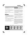
Caution!
Special safety instructions within this manu-
al are indicated with the triangle symbol
shown here, and have a gray background.
Caution! The microscope and accessories can
be damaged when operated incorrectly.
Explanatory note.
Instructions on disposing of the microscope,
accessory components and consumables.
Item not contained in all configurations.
Text symbols, pictograms and their meanings:
Caution!
This operating manual is an essential com-
ponent of the microscope, and must be read
carefully before the microscope is assem-
bled and put into operation.
1. Important notes about this manual
This operating manual contains important in-
structions and information for the operational
safety and maintenance of the microscope and
accessories. It must therefore be kept safely for
future reference.

8
2. Intended purpose of the microscope
2. Intended purpose of the microscope
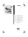
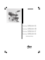
The DM4000 – DM5000 microscopes to which
these operating instructions belong, and which
have the identifying letter B, are intended for
biological routine and research applications.
This includes examining specimens taken from
the human body for the purpose of gaining infor-
mation about physiological or pathological con-
ditions or inborn anomalies, or testing for safety
and compatibility for potential recipients, or for
monitoring therapeutic measures.
The microscopes that have the identifying let-
ters M or P are intended for materials science,
geological or mineralogical examinations.
The above-named microscopes comply with the
Council Directive 98/79/EEC concerning in vitro
diagnostics. They also conform to the Council
Directives 73/23/EEC concerning electrical ap-
paratus and 89/336/EEC concerning electromag-
netic compatibility for use in an industrial envi-
ronment.
Caution!
The manufacturer assumes no liability for
damage caused by, or any risks arising from
using the microscopes for other purposes
than those for which they are intended or
not using them within the specifications of
Leica Microsystems CMS GmbH.
In such cases the declaration of conformity
shall cease to be valid.
Caution!
These (IVD) instruments are not intended for
use in the patient environment defined by
DIN VDE 0100-710. Nor are they designed to
be combined with medical instruments in
accordance with EN 60601-1. If a
microscope is electrically connected to a
medical instrument in accordance with
EN 60601-1, the requirements defined in
EN 60601-1-1 shall apply.

9
3. Safety notes
3. Safety notes
3.1 General safety notes
This safety class 1 device was built and tested
in accordance with the safety regulations for
electrical measuring, control, regulating and
laboratory devices in accordance with
EN 61010-2-101:2002
EN 61010-1:2001
IEC 1010-1:2001
Caution!
In order to maintain this condition and to en-
sure safe operation, the user must follow the
instructions and warnings contained in this
operating manual.
Caution!
The devices and accessories described in
this operating manual have been tested for
safety and potential hazards.
The responsible Leica affiliate or the main
plant in Wetzlar, Germany, must be consult-
ed whenever the device is altered, modified
or used in conjunction with non-Leica
components that are outside of the scope of
this manual.
Unauthorized alterations to the device or
noncompliant use shall void all rights to any
warranty claims and void product liability!

10
3. Safety notes
Caution!
The power plug may only be plugged into an
outlet equipped with a grounding contact.
Do not interfere with the grounding func-
tion by using an extension cord without a
ground wire. Any interruption of the ground
wire inside or outside of the device, or re-
lease of the ground wire connection, can
cause the device to become hazardous.
Intentional ground interruption is not permit-
ted!
Caution!
Through connection to the grounding con-
nection, ancillary equipment with its own
and/or extra power supply may be brought
to the same ground wire potential. For con-
nections without a ground connector, Leica
Service must be consulted.
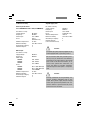
90-250 V~
50-60 Hz
max. 155VA
2xT2A (IEC 127)
10-36°C
max. 80% to 30°C
II
2
90-250 V~
50-60 Hz
max. 290VA
T6.3 A
(IEC 60127-2/3)
15-35°C
max. 80% to 30°C
II
2
3.2 Electrical safety
General specifications
Leica CTR5000 electronics box (for DM5000 B)
For indoor use only.
Supply voltage:
Frequency:
Power input:
Fuses:
Ambient temperature:
Relative humidity:
Overvoltage category:
Pollution degree:
Microscope
For indoor use only.
Supply voltage:
Frequency:
Power input:
DM4000
DM4500
DM5000
Fuses:
DM4000
DM4500
DM5000
Ambient temperature:
Relative humidity:
Overvoltage category:
Pollution degree:
ebq 100 supply unit*
For indoor use only.
Supply voltage:
Frequency:
Power input:
Fuses:
Ambient temperature:
Relative humidity:
Overvoltage category:
Pollution degree:
(see enclosed manual)
90-250 V~
50-60 Hz
max. 180 VA
max. 180 VA
max. 290VA
T6.3 A (IEC 60127-2/3)
T6.3 A (IEC 60127-2/3)
See CTR5000
15-35°C
max. 80% to 30°C
II
2

11
3. Safety notes
Caution!
Never use any fuses as replacements other
than those of the types and the current rat-
ings listed here. Bypassing fuse holders is
not permitted.
Caution!
The microscope’s electrical accessory com-
ponents are not protected against water.
Water can cause electric shock.
Caution!
Protect the microscope from excessive tem-
perature fluctuations. Such fluctuations can
lead to the accumulation of condensation,
which can damage the electrical and opti-
cal components.
Operating temperature: 15-35°C
Caution!
Before exchanging the fuses or lamps, be
absolutely certain to switch off the main
power switch and remove the power cable.
3.3 Disposal
Once the product has reached the end of its ser-
vice life, please contact Leica Service or Sales
about disposal.
Please observe and comply with the national
and federal laws and regulations that are equiv-
alent to EU guidelines such as WEEE.
Note!
Like all electronic devices, the microscope,
its accessory components and consumables
must never be disposed of with general
household waste.

12
4. Overview of the instrument
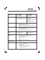
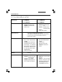
4. Overview of the instrument
Specification
Contrast methods
Transmitted light axis
Incident light axis
Z pinion
Objective turret
Leica DM4000 B
Leica DM5000 B
• Transmitted light:
DM4000 B: BF, DF, PH, Pol
DM5000 B: and ICT (mot.)
• Incident light: Fluorescent
• Integrated into the stand
• Motorized 5x filter turret disk
(DM5000 B 8x optional)
• With FIM (fluorescence in-
tensity manager) for reduc-
ing the light intensity in 5 in-
crements
• Mechanical booster lens for
increasing fluorescence in-
tensity
• Motorized shutter
• Manual, fully encoded
• DM4000 B: 6x/7x with
M25 thread
DM5000 B: 7x (M25)
DM5000 B: With object prism
disk (3 positions)
Leica DM4000 M
Leica DM4500 P
• Transmitted light:
DM4000 M: BF, DF, PH, ICT,
Pol
DM4500 P: BF, DF, PH, ICT,
Pol (conoscopy)
• Incident light:
BF, DF, ICR, Pol, Fluo
• Integrated into the stand
• Motorized 4x filter turret
disk
• Automatic
illumination manager
• DM4000 M: motorized
shutter
• Manual, fully encoded
• DM4000 M: 6x with
M32 thread
DM4500 P: 6x with
M25 thread, centerable,
encoded
• Receptacle for DIC prisms
and Pol compensators
(for DM4000 M: optional)
• Automatic illumination manager (mot. aperture diaphragm
and field diaphragm, mot. intensity control)
• Automatic constant-color intensity control
• Motorized shutter
• Manual

13
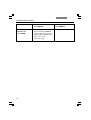
4. Overview of the instrument
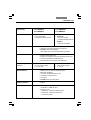
Specification
X/Y stage
Tube
Condenser
Magnification changer
(optional)
Controls
Computer interface
Software tools
Leica DM4000 B
Leica DM5000 B
• Manual
• Replaceable specimen stage
• Coaxial drive length: 155 mm
• Manual
• 3x fully encoded
• 1x; 1.25x; 1.6x
Leica DM4000 M
Leica DM4500 P
• Manual
• DM4000 M:
•
Replaceable specimen stage
•
Coaxial drive length: 140 mm
DM4500 P:
• Replaceable Pol stage
• Manual
• 3x fully encoded
• 1x; 1.5x; 2x
• Motorized condenser head
• Condenser disk for the light ring, DF-Stop, DIC prisms
• Automatic Köhler illumination
• Optional polarizer (integrated and motorized)
• Operating buttons on the stand for all motorized
microscope functions
• Additional variable multifunction keys
• Focus wheels
• LCD
• DM5000 B with Leica SmartTouch
• USB2.0
• Leica Application Suite (LAS)
for Windows
TM
2000, XP, Vista
• With plug-ins for:
• Microscope and camera configuration
• Microscope and camera control
• Image acquisition
• Manual or motorized (DM4500P: manual)
• Optionally with one or two camera outputs
• DM4500 P: conoscopy module
(tube optics HC P1x/1.6x with Bertrand lens, encoded)

14
4. Overview of the instrument
Leica DM4000 B
Leica DM5000 B
Only for the Leica DM5000 B:
Separate operating unit with a
power supply for 100 W halogen
lamps. See → p.10
(Electrical safety)
Leica DM4000 M
Leica DM4500 P
Specification
Electronics box
Leica CTR5000

15
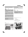
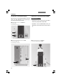
4. Overview of the instrument
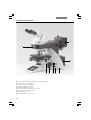
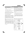
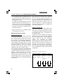
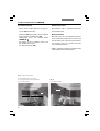
1 Eyepiece
2 Eyepiece tube
3 Tube
4 Objective turret with objectives
5 Specimen stage with specimen holder
6 Condenser
7 LCD
8 Field diaphragm operating buttons
9 Transmitted light / incident light switch
10 Aperture diaphragm operating buttons
11 Brightness adjustment buttons
12 Focus wheel with coarse and fine adjustment
13 Variable function keys (preset at the factory)
14 Lamp adjustment window
Fig. 1 Left side of the stand with the advanced AET22 ErgoTube
1
2
3
4
5
6
7
891011
12
13
14

16
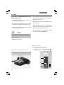
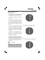
4. Overview of the instrument
15 Lamp housing for incident light
16 Lamp housing for transmitted light
17 Transmitted light filter, optional
18 Transmitted light filter, optional
19 Variable function keys (preset at the factory)
20 x/y coaxial drive, adjustable height
21 Handwheel for fine focus
22 Motorized filter block exchanger
Fig. 2 Right side of the stand with the advanced ErgoTube AET22
22
21 20 19 18 17
15
16

17
5. Unpacking the microscope
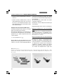
The microscope is delivered in two packages.
The stand package contains the following com-
ponents:
• Stand with integrated incident light axis and
objective turret
• Specimen stage with stage bracket
• Power cable and PC connecting cable
• CD with Leica Application Suite (LAS) soft-
ware package
• Instructions and list of microscope default
settings
The system package contains the microscope’s
accessories:
• Tube
• Eyepieces
• Objectives
• Condenser
• Lamp housings with accessories
• Assembly tools
• Additional microscope accessories such as
filter cubes, etc. depending on product con-
figuration
The external ebq 100 supply unit* is delivered in
a separate package.
For the Leica DM5000 B microscope:
The Leica CTR5000 electronics box is delivered
in a separate package.
First, carefully remove all components from the
transportation and packaging materials.
Note:
If at all possible, avoid touching the lens surfac-
es of the objectives. If fingerprints do appear on
the glass surfaces, remove them with a soft
leather or linen cloth. Even small traces of finger
perspiration can damage the surfaces of optical
devices in a short time. See the chapter on "Care
of the microscope" →
p. 77 for additional in-
structions.
Caution!
Do not connect the microscope or periph-
erals to an AC power source at this time
under any circumstances!
5. Unpacking the microscope

18
5. Unpacking the microscope
Installation location
Work with the microscope should be performed
in a dust-free room, which is free of oil vapors
and other chemical vapors, as well as extreme
humidity. At the workstation, large tempera-
ture fluctuations, direct sunlight and vibrations
should be avoided. These conditions can distort
measurements and micrographic images.
Allowable ambient conditions
Temperature 15-35°C
Relative humidity maximum 80% up to 30°C
Microscopes in warm and warm-damp climatic
zones require special care in order to prevent
the build up of fungus.
See the chapter on "Care of the microscope" →
p. 77 for additional instructions.
Caution!
Electrical components must be assembled at
least 10 cm away from the wall and from
flammable substances.
Transport
For shipping or transporting the microscope
and its accessory components, the original
packaging should be used.
As a precaution to prevent damage from vibra-
tions, the following components should be dis-
assembled and packaged separately:
• Unscrew the objectives.
• Remove the condenser.
• Remove the specimen stage.
• Remove the lamp housings.
• Disassemble the burner of 106 z lamp housing.
• Remove all moving or loose parts.

19
6. Assembly
6. Assembling the microscope
The microscope components are logically as-
sembled in this order:
• Specimen stage
• Condenser with condenser head
• Tube
• Eyepieces
• Objectives
• Lamp housings with light sources
• Equipment for the incident light turret disk*
Only a few commonly used screwdrivers and
keys are necessary for assembly; these are in-
cluded in the delivery package.
When using intermediate systems and optical
accessories, the sequence may vary.
In this case, read chapter,
"6.10 Optional accessories" →
p.33
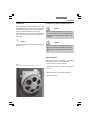
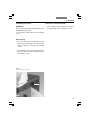
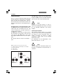
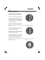
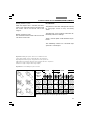
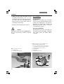
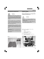
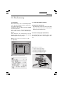
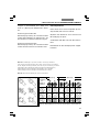
6.1 Specimen stage
Caution:
Never install objectives before assembling the
stage.
• Place the specimen holder on the stage and
fasten it with the two screws (3.1).
• Using the condenser height adjuster (3.2), turn
the condenser holder completely upwards,
i.e. as close to the stage as possible.
• Loosen the stage clamp (3.3) slightly.
23
1
Fig. 3 Mechanical object stage
1 Locking screws for specimen holder
2 Condenser height adjuster
3 Stage clamp
!

20
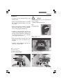
6. Assembly
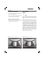
• Only for DM4500 P:
Pol attachable mechanical stage*
Adjust the attachable mechanical stage so
that the fastening screw is visible below the
holes (4a.1). Set the attachable mechanical
stage in the guide holes on the rotating stage
and tighten the fastening screw using the
hexagonal key.
Attachable mechanical stage*
The attachable mechanical stage can be in-
stalled on the left, on the right or on the front
(not pictured). The two clamping screws fas-
ten it into place.
• From above, set the stage clamp onto the
dovetail guide (4.2) and push the stage down-
wards until the upper end of the dovetail
guide is tightly fastened to the upper end of
the stage clamp.
• Firmly tighten the stage clamp (4.1).
Note:
For thicker specimens (Leica DM4000 M) the
stage can be set to a correspondingly lower level.
Fig. 4 Assembling the stage
1 Stage clamp
2 Dovetail guide
Fig. 4a Pol rotating stage* and Pol 3 attachable mechani-
cal stage*
1 Holes for the fastening screw.
2 Lever for the holder for glass slides of various formats,
which can be turned inward and outward
3 Storage for the centering key
4 Locking button pair
5 45° click stop
6 Clamping system for the stage rotation
1
2
3
5
6
4
1
2

21
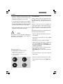
6. Assembly
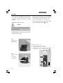
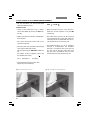
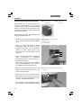
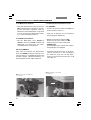
6.2 Condenser
• Screw the condenser head into the condenser.
• Using the condenser height adjuster (5.4), turn
the condenser holder (5.1) downward as far
as it will go.
• Unscrew the clamping screw for the con-
denser (5.3) far enough so that the condenser
can be inserted from the front.
• From the front, insert the condenser into the
condenser holder as far as it will go. On the
underside of the condenser, there is an orien-
tation pin (6.1) that must be locked into place
in the guiding notch (7.1).
• Tighten the condenser’s clamping screw (5.3)
until the condenser locks into place.
• Connect the condenser over the connection
(8.1) with the stand.
Fig. 5 Condenser holder
1 Condenser holder
2 Condenser centering
3 Clamping screw for the condenser
4 Condenser height adjuster
Fig. 6
Underside of condenser
1 Orientation pin
Fig. 7 Condenser holder
1 Guiding groove
1
1
Fig. 8 Condenser connection
1 Condenser cable socket
Note:
The condenser must be centered before using
the microscope.
→
Köhler illumination p. 41.
1
23 4
1

22
6. Assembly
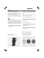
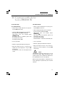
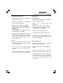
6.3 Tube and eyepieces
The tube is mounted on the stand either directly
or with the use of intermediate modules. The
side clamping screw fastens it into place (9b.1).
•
For the MBDT motorized tube only:
Remove the transport anchor (9a.1) on the un-
derside of the tube.
• Partially unscrew the clamping screw (9b.1).
• Insert the tube into the circular receptacle
(dovetail ring).
• Retighten the clamping screw (9b.1).
•
For the MBDT motorized tube only:
Connect the tube to the stand with the con-
nector bushing (10.1).
Fig. 9b Fastening the tube
1 Clamping screw
1
Fig. 10 Motorized tube connection
1 Connector socket
1
Fig. 9a Underside of the tube
1 Transport anchor
1
• The eyepieces are inserted into the eyepiece
tubes on the tube.
•
For the BDTP tube only:
The Pol eyepieces are inserted into the eye-
piece tubes (using the locking groove).
Page is loading ...
Page is loading ...
Page is loading ...
Page is loading ...
Page is loading ...
Page is loading ...
Page is loading ...
Page is loading ...
Page is loading ...
Page is loading ...
Page is loading ...
Page is loading ...
Page is loading ...
Page is loading ...
Page is loading ...
Page is loading ...
Page is loading ...
Page is loading ...
Page is loading ...
Page is loading ...
Page is loading ...
Page is loading ...
Page is loading ...
Page is loading ...
Page is loading ...
Page is loading ...
Page is loading ...
Page is loading ...
Page is loading ...
Page is loading ...
Page is loading ...
Page is loading ...
Page is loading ...
Page is loading ...
Page is loading ...
Page is loading ...
Page is loading ...
Page is loading ...
Page is loading ...
Page is loading ...
Page is loading ...
Page is loading ...
Page is loading ...
Page is loading ...
Page is loading ...
Page is loading ...
Page is loading ...
Page is loading ...
Page is loading ...
Page is loading ...
Page is loading ...
Page is loading ...
Page is loading ...
Page is loading ...
Page is loading ...
Page is loading ...
Page is loading ...
Page is loading ...
Page is loading ...
Page is loading ...
Page is loading ...
Page is loading ...
Page is loading ...
Page is loading ...
Page is loading ...
Page is loading ...
Page is loading ...
Page is loading ...
Page is loading ...
Page is loading ...
Page is loading ...
Page is loading ...
Page is loading ...
Page is loading ...
Page is loading ...
Page is loading ...
Page is loading ...
Page is loading ...
Page is loading ...
Page is loading ...
Page is loading ...
Page is loading ...
Page is loading ...
Page is loading ...
Page is loading ...
Page is loading ...
Page is loading ...
Page is loading ...
Page is loading ...
Page is loading ...
Page is loading ...
Page is loading ...
Page is loading ...
Page is loading ...
Page is loading ...
Page is loading ...
Page is loading ...
Page is loading ...
Page is loading ...
Page is loading ...
Page is loading ...
Page is loading ...
Page is loading ...
Page is loading ...
Page is loading ...
Page is loading ...
Page is loading ...
Page is loading ...
Page is loading ...
Page is loading ...
Page is loading ...
Page is loading ...
Page is loading ...
Page is loading ...
Page is loading ...
Page is loading ...
Page is loading ...
Page is loading ...
Page is loading ...
Page is loading ...
Page is loading ...
Page is loading ...
Page is loading ...
Page is loading ...
Page is loading ...
Page is loading ...
Page is loading ...
Page is loading ...
Page is loading ...
Page is loading ...
Page is loading ...
Page is loading ...
Page is loading ...
Page is loading ...
Page is loading ...
Page is loading ...
Page is loading ...
Page is loading ...
Page is loading ...
Page is loading ...
Page is loading ...
Page is loading ...
-
 1
1
-
 2
2
-
 3
3
-
 4
4
-
 5
5
-
 6
6
-
 7
7
-
 8
8
-
 9
9
-
 10
10
-
 11
11
-
 12
12
-
 13
13
-
 14
14
-
 15
15
-
 16
16
-
 17
17
-
 18
18
-
 19
19
-
 20
20
-
 21
21
-
 22
22
-
 23
23
-
 24
24
-
 25
25
-
 26
26
-
 27
27
-
 28
28
-
 29
29
-
 30
30
-
 31
31
-
 32
32
-
 33
33
-
 34
34
-
 35
35
-
 36
36
-
 37
37
-
 38
38
-
 39
39
-
 40
40
-
 41
41
-
 42
42
-
 43
43
-
 44
44
-
 45
45
-
 46
46
-
 47
47
-
 48
48
-
 49
49
-
 50
50
-
 51
51
-
 52
52
-
 53
53
-
 54
54
-
 55
55
-
 56
56
-
 57
57
-
 58
58
-
 59
59
-
 60
60
-
 61
61
-
 62
62
-
 63
63
-
 64
64
-
 65
65
-
 66
66
-
 67
67
-
 68
68
-
 69
69
-
 70
70
-
 71
71
-
 72
72
-
 73
73
-
 74
74
-
 75
75
-
 76
76
-
 77
77
-
 78
78
-
 79
79
-
 80
80
-
 81
81
-
 82
82
-
 83
83
-
 84
84
-
 85
85
-
 86
86
-
 87
87
-
 88
88
-
 89
89
-
 90
90
-
 91
91
-
 92
92
-
 93
93
-
 94
94
-
 95
95
-
 96
96
-
 97
97
-
 98
98
-
 99
99
-
 100
100
-
 101
101
-
 102
102
-
 103
103
-
 104
104
-
 105
105
-
 106
106
-
 107
107
-
 108
108
-
 109
109
-
 110
110
-
 111
111
-
 112
112
-
 113
113
-
 114
114
-
 115
115
-
 116
116
-
 117
117
-
 118
118
-
 119
119
-
 120
120
-
 121
121
-
 122
122
-
 123
123
-
 124
124
-
 125
125
-
 126
126
-
 127
127
-
 128
128
-
 129
129
-
 130
130
-
 131
131
-
 132
132
-
 133
133
-
 134
134
-
 135
135
-
 136
136
-
 137
137
-
 138
138
-
 139
139
-
 140
140
-
 141
141
-
 142
142
-
 143
143
-
 144
144
-
 145
145
-
 146
146
-
 147
147
-
 148
148
-
 149
149
-
 150
150
-
 151
151
-
 152
152
-
 153
153
-
 154
154
-
 155
155
-
 156
156
-
 157
157
-
 158
158
-
 159
159
-
 160
160
-
 161
161
-
 162
162
-
 163
163
-
 164
164


Sharp DM-4500 User manual
- Category
- Print & Scan
- Type
- User manual
Ask a question and I''ll find the answer in the document
Finding information in a document is now easier with AI
in other languages
- Deutsch: Sharp DM-4500 Benutzerhandbuch
Other documents
-
Leica DM5000B User manual
-
Accu-Scope EXI-410-FL Inverted Microscope Operating instructions
-
-
-
-
Bresser Science TRM 301 Microscope Owner's manual
-
-
 Hey! Play! M330022 Operating instructions
-
-
Bresser Junior MicroSet 40x-1024x Owner's manual
