Page is loading ...

Phone/Tel. +49 (0) 64 41-29 22 86
Fax +49 (0) 64 41-29 22 55
E-mail/Email [email protected]
Published May 2005 by/
Herausgegeben Mai 2005 von:
Leica Microsystems Wetzlar GmbH
Ernst-Leitz-Straße
D-35578 Wetzlar (Germany)
Responsible for contents/
Verantwortlich für den Inhalt:
Bernard Kleine
(Marketing CMS, Life Science Research
Microscopy, Product Management)
Holger Grasse
(Safety Officer according to MPG §30/
Sicherheitsbeauftragter nach MPG §30)
In case of questions, please contact the hotline/
Bei Fragen wenden Sie sich bitte an die Hotline:

4
Copyrights
Copyrights
All rights to this documentation are held by
Leica Microsystems Wetzlar GmbH. Reproduc-
tion of text or illustrations (in whole or in part) by
print, photocopy, microfilm or other method (in-
cluding electronic systems) is not allowed with-
out express written permission from Leica
Microsystems Wetzlar GmbH.
The term “Windows” may appear in the follow-
ing text without further identification. It is, how-
ever, a registered trademark of Microsoft Corpo-
ration. The names of companies and products
used herein may be trademarks of their respec-
tive owners.
The instructions contained in the following
documentation reflect state-of-the-art technol-
ogy and knowledge standards. We have com-
piled the texts and illustrations as accurately as
possible. Nevertheless, no liability of any kind
may be assumed for the accuracy of this manu-
al’s contents. Still, we are always grateful for
comments and suggestions regarding potential
mistakes within this documentation.
The information in this manual is subject to
modification at any time and without notifica-
tion.

5
Contents
6.11 Installation of Lamp Housing Mount
and Mirror Housing ................................... 42
6.12 Installation and Replacement
of Incident-Light Lamps............................ 44
6.13 Equipping the
Incident Light Turret Disk......................... 48
6.14 Inserting the Front Module Slider ..........
6.15 Installation of the Polarizer
and Analyzer............................................... 50
6.16 Optional Accessories ............................... 52
6.17 Connection to the
Electronics Box CTR6000 ......................... 53
6.18 Connection to the Computer ................... 54
6.19 Connection to the Power Supply ............ 54
7. Startup ......................................................... 55
7.1 Functional Principle .................................. 55
7.2 Switching On .............................................. 59
7.3 The LeicaScreen........................................ 60
7.4 The Function Buttons on the Stand ....... 61
7.5 The SmartMove Remote
Control Module .......................................... 64
7.6 Illumination ................................................. 65
7.6.1 Transmitted light ............................. 65
7.6.2 Incident Light – Fluorescence ..... 68
7.7 Checking Phase Contrast Rings ............. 69
7.8 Setting the Motorized Polarizer.............. 70
7.9 Adjusting the Light Sources .................... 71
Contents
1. Important Notes about this Manual ...... 7
2. Intended Purpose of the Microscope ... 8
3. Safety Notes ............................................... 9
3.1 General Safety Notes ............................... 9
3.2 Electrical Safety ........................................ 10
4. Overview of the Leica DMI6000 ............. 12
4.1 Specifications ............................................ 12
4.2 Glossary....................................................... 16
5. Unpacking the Microscope .................... 22
6. Assembling the Microscope .................. 25
6.1 Assembly Tools .......................................... 25
6.2 Installation of the
Transmitted-Light Illumination Carrier .. 26
6.3 Installation of the DIC Module
and DIC Objective Prisms ........................ 27
6.4 Installation of Stages ................................ 28
6.5 Installation of Condensers....................... 34
6.6 Installation of Eyepieces.......................... 39
6.7 Installation of Objectives ......................... 39
6.8 Installation of Filters
in the Illumination Arm ............................. 40
6.9 Installation of the
Transmitted-Light Lamp Housing............ 40
6.10 Installation and Replacement of the......
Transmitted-Light Lamps:.........................
Lamp Housing 107 or 107/2 ...................... 41

6
Contents
8. Operation .................................................... 74
8.1 Switching On .............................................. 74
8.2. Contrast Methods...................................... 76
8.2.1 Bright Field (TL) ............................... 76
8.2.2 Phase Contrast (TL) ........................ 77
8.2.3 Dark Field (TL) ................................. 77
8.2.4 Polarization (TL) .............................. 78
8.2.5 Differential
Interference Contrast (TL) ............ 79
8.3 Fluorescence.............................................. 80
8.4 Combination Methods .............................. 81
8.5 Focusing ...................................................... 82
8.6 Tubes............................................................ 84
8.7 Eyepieces .................................................... 85
8.8 Objectives ................................................... 85
8.9 Stages and Object Displacement ........... 88
8.10 Magnification Changer............................. 89
8.11 Light Sources ............................................. 89
8.12 Aperture and Field Diaphragm................ 90
9. Troubleshooting......................................... 91
10. Care of the Microscope ........................... 95
10.1 Dust Cover .................................................. 95
10.2 Cleaning....................................................... 95
10.3 Handling Acids and Bases ...................... 96
11. Essential Wear and Spare Parts ............ 97
12. Dimensions................................................. 98
13. Abbreviations and Pictograms............... 99
14. Index ............................................................ 101
15. EU Declaration of Conformity ................. 104

7
1. Important Notes about this Manual
(1.2)
→
p. 20
!
*
Numbers in parentheses, such as “(1.2)”, corre-
spond to illustrations (in the example, Figure 1,
Item 2).
Numbers with pointer arrows (for example
→ p. 20), point to a certain page of this manual.
Caution!
Special safety instructions within this
manual are indicated with the triangle sym-
bol shown here, and have a gray back-
ground.
Caution! The microscope and accessories can
be damaged when operated incorrectly.
Explanatory note.
Item not contained in all configurations.
Text symbols, pictograms and their meanings:
Caution!
This operating manual is an essential com-
ponent of the microscope, and must be read
carefully before the microscope is assem-
bled, put into operation or used.
1. Important Notes about this Manual
This operating manual contains important in-
structions and information for the operational
safety and maintenance of the microscope and
accessories. It must therefore be kept safely for
future reference.
A separate manual is available on CD-ROM cov-
ering the operation of the Leica Application
Suite (LAS).

8
2. Intended Purpose of the Microscope
2. Intended Purpose of the Microscope
The microscopes of the Leica DMI series cov-
ered in this manual are designed for biological
routine and research applications. This includes
the examination of samples taken from the hu-
man body with a view to providing information
on physiological or pathological states or con-
genital abnormalities, or to determining the
safety and compatibility with potential recipi-
ents, or to monitoring therapeutic measures.
The Leica DMI series is a further development of
Leica’s proven inverted research microscopes.-
It is designed for cellular and tissue examina-
tion, micromanipulation and microinjection
techniques, microdissection and confocal
microscopy. The Leica DMI series is suitable for
universal deployment. All contrast methods
such as dark field, bright field, phase contrast,
DIC, fluorescence (not DMI 3000) and modula-
tion contrast are integral to the microscope and
can be adapted or changed quickly and easily.
Variable illumination and imaging beam paths,
as well as HCS optics, modular accessories and
a comprehensive range of peripherals comple-
ment the Leica Microsystems inverted research
stand.
The above-named microscope complies with
the Council Directive 98/79/EEC concerning in
vitro diagnostics. They also conform to the
Council Directives 73/23/EEC concerning electri-
cal apparatus and 89/336/EEC concerning elec-
tromagnetic compatibility for use in an industrial
environment.
Caution!
The manufacturer assumes no liability for
damage caused by, or any risks arising from
using the microscopes for other purposes
than those for which they are intended or
not using them within the specifications of
Leica Microsystems Wetzlar GmbH.
In such cases the declaration of conformity
shall cease to be valid.
Caution!
This (IVD) device is not intended for use in
the patient environment defined by DIN VDE
0100-710. Neither is it intended for combin-
ing with medical instruments according to
EN 60601-1. If a microscope is electrically
connected to a medical instrument accord-
ing to EN 60601-1, the requirements defined
in EN 60601-1-1 shall apply.

9
3. Safety Notes
3. Safety Notes
3.1 General Safety Notes
This safety class 1 device is constructed and
tested in accordance with
EN 61010-2-101:2002,
EN 61010-1:2001,
IEC 1010-1:2001,
Safety regulations for electrical measuring, con-
trol, and laboratory devices.
Caution!
In order to maintain this condition and to en-
sure safe operation, the user must follow the
instructions and warnings contained in this
operating manual.
Caution!
The devices and accessories described in
this operating manual have been tested for
safety and potential hazards.
The responsible Leica affiliate or the main
plant in Wetzlar must be consulted when-
ever the device is altered, modified or used
in conjunction with non-Leica components
that are outside of the scope of this manual.
Unauthorized alterations to the device or
noncompliant use shall void all rights to any
warranty claims!

10
3. Safety Notes
Caution!
Power plugs may only be plugged into an
outlet equipped with a grounding contact.
Do not interfere with the grounding function
by using an extension cord without a ground
wire. Any interruption of the ground wire in-
side or outside of the device, or release of
the ground wire connection, can cause the
device to become hazardous. Intentional
ground interruption is not permitted!
Caution!
Peripheral devices with their own or sepa-
rate power supplies that are connected to
the microscope can have the same protec-
tive conductor potential by connecting them
to the ground screw on the back of the Leica
CTRxxxx electronics boxes. For connections
without a ground connector, Leica Service
must be consulted.
Caution!
Never use any fuses as replacements other
than those of the types and the current rat-
ings listed here. Using patched fuses or
bridging the fuse holder is not permitted. The
use of incorrect fuses may result in a fire
hazard.
3.2 Electrical Safety
General specifications
Leica CTR4000, CTR6000 and CTR6500 electron-
ics boxes
For indoor use only.
Supply voltage:
Frequency:
Power input:
Fuses:
Ambient temperature:
Relative humidity:
Overvoltage category:
Pollution degree:
Microscope
For indoor use only.
Supply voltage:
Frequency:
Power input:
Fuses:
Ambient temperature:
Relative humidity:
Overvoltage category:
Pollution degree:
ebq 100 supply unit*
For indoor use only.
Supply voltage:
Frequency:
Power input:
Fuses:
Ambient temperature:
Relative humidity:
Overvoltage category:
Pollution degree:
(see enclosed manual)
90–250 V~
50–60 Hz
max. 290 VA
T6.3 A
(IEC 60127-2/3)
15–35°C
max. 80% to 30°C
II
2
90–250 V~
50–60 Hz
see CTRxxxx
see CTRxxxx
15–35°C
max. 80% to 30°C
II
2
90–250 V~
50–60 Hz
max. 155VA
2xT2A (IEC 127)
10–36°C
max. 80% to 30°C
II
2

11
3. Safety Notes
Caution!
The microscope’s electrical accessory com-
ponents are not protected against water.
Water can cause electric shock.
Caution!
Protect the microscope from excessive tem-
perature fluctuations. Such fluctuations can
lead to the accumulation of condensation,
which can damage the electrical and optical
components.
Ambient temperature: 15–35°C.
Caution!
Before exchanging the fuses or lamps, be
absolutely certain to switch off the main
power switch and remove the power cable.

12
4. Overview of the Instrument
4.1 Specifications
4. Overview of the Leica DMI Series
Contrast Methods
Transmitted Light Axis
Leica DMI Series
• transmitted light (DL): BF, DF, PH, DIC, Pol
• intermediate pupil:
IMC (integrated modulation contrast)
IPH (Integrated phase contrast)
Leica DMI4000B and DMI6000B
• incident light (IL): Fluo
• combination (DL/IL): Fluo/DIC, Fluo/PH
Leica DMI Series
For the Leica DMI3000B, a manual version of this
illumination arm is always a component of the stand.
• Manual and coded transmitted-light illumination arm with inte-
grated mechanical tilt mechanism to provide adequate space
for specimens and micromanipulators, integrated field dia-
phragm, filter magazine for 2 replaceable filters, condenser
quick-changer
•
Illumination Manager (aperture diaphragm, field diaphragm, light
intensity)
• manual shutter
• lamp housing mount for interchangeable lamp housings.
• with integrated cable channel
Leica DMI4000B and Leica DMI6000B
• Motorized or manual/coded transmitted-light illumination arm
with integrated mechanical tilt mechanism to provide adequate
space for specimens and micromanipulators, integrated motor-
ized field diaphragm, motorized filter magazine for 2 replace-
able filters, condenser quick-changer
• with integrated cable channel
• automatic Illumination Manager
(aperture, field diaphragm, intensity, process switching)
• automatic constant-color intensity control
• manual or motorized shutter
• lamp housing mount for interchangeable lamp housings.
• automatic, electronic condenser identification

13
4. Overview of the Instrument
Leica DMI4000B and Leica DMI6000B
• automatic Illumination Manager
(aperture, field diaphragm, intensity, process switching)
• motorized shutter (switching speed < 50 ms)
• lamp housing mount for up to 3 interchangeable light sources
• motorized 6-place filter turret
• Fluorescence Intensity Manager (FIM)
(reduction of incident illumination intensity)
• mechanical booster lens for central boosting of
fluorescence or uniform distribution
• motorized Excitation Manager to monitor fluorescence emission
when using double and triple filter cubes
• ultrafast filter wheel for 3 excitation wavelengths
(switching speed < 50 ms)
Leica DMI Series
• ergonomic with or without camera port at left
•2 switching positions: 100%VIS and 50%VIS / 50%CAM or
•2 switching positions: 100%VIS and 0%VIS / 100%CAM
• optional Bertrand lens
• eye spacing adjustment
• height and angle adjustment (30° - 45°)
Leica DMI4000B and Leica DMI6000B
• motorized
•3 switching positions
(choice of magnifications: 1x; 1.5x; 1.6x or 2.0x)
• effective on all camera ports and eyepieces
or
Leica DMI Series
• manual
•2 switching positions
(choice of magnifications: 1x; 1.5x; 1.6x or 2.0x)
• effective on tube port and eyepieces
Leica DMI6000B
• motorized and coded
• 6x for objectives with M25 thread and 45mm parfocal distance
• for DIC: motorized or manual/coded Wollaston prism carousel
• anti-vibration locking
Incident light axis
Tube
Magnification Changer
Objective Turret

14
4. Overview of the Instrument
Leica DMI4000B
• manual and coded
• 6x for objectives with M25 thread and 45mm parfocal distance
• for DIC: motorized or manual/coded Wollaston prism carousel
Leica DMI3000B
• manual
• 6x for objectives with M25 thread and 45 mm parfocal distance
• for DIC: manual Wollaston prism carousel
Leica DMI Series
Fixed regular stages
• Ceramic-coated stage plate (248 mm x 204 mm)
• heating stage plate (3°C above room temperature to 60°C)
(248 x 212 mm)
• temperature-controlled stage plate (0°C to 60°C)
(248mm x 212 mm)
• fixed micromanipulation stages
• ceramic-coated stage plate (248 mm x 204/122 mm)
• heated stage plate (from 3°C above room temperature
to 60°C)
(248 mm x 204/122 mm)
• temperature-controlled stage plate (0°C to 60°C)
(248 mm x 204/122 mm)
• regular manual and motorized 3-plate cross-stage
• positioning range: 83 mm x 127 mm
• 20 optional inserts (standard, heating, cooling) for a variety
of applications, size of inserts:160 mm x 110 mm (compatible
with scanning stages)
• narrow manual and motorized micromanipulation
3-plate cross-stage
• positioning range: 40 mm x 40 mm
•3 optional inserts for a variety of applications
• Scanning stage IM 120 x 100 (motors on bottom)
•1 mm, 2 mm, 4 mm spindle pitch
(higher resolution vs. higher speed)
• 20 optional inserts (standard, heating, cooling) for a variety of
applications, size of inserts:160 mm x 110 mm
Objective Turret
Stages

15
4. Overview of the Instrument
Condensers
Z focus
Observation ports
Leica DMI4000B and Leica DMI6000B
(identical for Leica DMI3000B, but manual)
• motorized and coded or manual and coded
• motorized or manual aperture diaphragm
• contrast methods: BF, DF, PH, DIC, Pol, IMC, IPH
• automatic method switching
• condenser turret with 7 positions for contrast methods
•2 condenser housings (S1-S28 and S70)
• condenser heads: S1/1.4 oil, S1/0.9 dry, S23/0.53, S28/0.55
• condenser heads can be swung out
• condenser S70 with additional lens for low magnifications
• all condensers suitable for magnifications from 1.25x to 100x
• with or without motorized or manual polarizer
• with or without motorized or coded Wollaston prism disk
Leica DMI6000B
• motorized and coded
•9 mm travel (1 mm below, 8 mm above the stage)
• maximum travel speed: 5 mm/s
•5 focus steps: 0.05 µm; 0.1 µm; 0.7 µm; 1.5 µm; 5.0 µm
• electronic focus repositioning
• automatic lowering prior to objective change
• electronic parfocality
Leica DMI3000B and Leica DMI4000B
• manual
•9 mm travel (1 mm below, 8 mm above the stage)
Leica DMI4000B and Leica DMI6000B
• motorized and coded
• left side ports (100%, 80% or 50% transmission)
• left side port dichroic splitting at 680 nm
• right side ports (100%, 80% or 50% transmission)
• bottom port
optional
• top port with 2 switching positions
• 100% to eyepieces
50% to eyepieces/ 50% to port

16
4. Overview of the Instrument
Observation ports
Controls
Electronics box
Leica DMI3000B
(a manual side port is a standard feature of the Leica DMI3000B
stand)
• manual
• left side port (80% transmission)
Leica DMI4000B and Leica DMI6000B
•7 fixed control buttons for illumination and apertures
•7 variable function buttons behind the focus controls
•3 fixed control buttons for focus stops (Leica DMI6000B only)
•2 focus hand wheels
•7 buttons for fluorescence cubes and shutters
•4 buttons for magnification changer and ports
• SmartMove: ergonomic remote control module for x,y,z control
and four additional variable function buttons
Leica DMI3000B
•2 focus hand wheels
•1 illumination hand wheel
•1 On/Off switch
• separate control unit for all motorized and electronic elements of
the microscope such as:
For CTR6500 only
• scanning stages
For CTR6000 only
• motorized 3-plate cross-stages
For CTR6000
• objective turret
• focus
• ports
• magnification changer
• fluorescence
• condenser
• power supply for SmartMove
For all CTR boxes
with
• power supply for 100W halogen lamps

17
4. Overview of the Instrument
Leica DMI4000B and Leica DMI6000B
•2 x RS232C
•2 x USB
•4 x external/internal peripherals
• CTR boxes
• SmartMove
Leica DMI4000B and Leica DMI6000B
• Leica Application Suite (LAS) for Windows
TM
2000, XP with
plug-ins for:
• microscope and camera configuration
• microscope and camera control
• image acquisition
Interfaces
Software tools

18
4. Overview of the Instrument
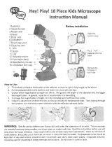
Fig. 1 Left side, Leica DMI4000 B and DMI6000B
1 Eyepiece
2 Eyepiece tube
3 Top port
4 Intermediate pupil interface
5 LeicaScreen
6 Light intensity
7 Field diaphragm
8 TL/IL switching
9 Aperture diaphragm
10 Focus wheel (motorized Leica DMI6000B,
manual (fine and coarse) Leica DMI4000B)
11 Variable function buttons
12 Left side port
13 Booster lens (fluorescence microscopes only)
14 Lamp mount (fluorescence microscopes only)
15 Condenser head
16 Condenser base
17 Field diaphragm
18 Transmitted-light lamp housing
19 DIC objective prism disk
1
2
3
4
5
678910111213
14
15
17
16
18
19

19
4. Overview of the Instrument
Fig. 2 R
ight side Leica DMI4000B and DMI6000B
1 E-Focus buttons (Leica DMI6000B only)
2 Focus wheel (motorized Leica DMI6000B,
manual (fine) Leica DMI4000B)
3 Variable function buttons
4 Opener for drawer (fluorescence microscopes only)
5 Drawer (fluorescence microscopes only)
6 Right side port
7 Analyzer slot
8 Centering window (fluorescence microscopes only)
9 Field diaphragm centering
(fluorescence microscopes only)
10
Incident-light lamp housing (fluorescence microscopes
only)
11 Objective turret
12 Stage with attachable mechanical stage
12 3
4
5
678
12
910
11

20
4. Overview of the Instrument
Fig. 3 Front view Leica DMI4000 B and Leica DMI6000B
1 LeicaScreen
2 Front control panel
3 Port switching
4 Top port
5 Manual transmitted-light filters
6 Bertrand lens centering
1
2
3
4
6
5

21
4. Overview of the Instrument
Fig. 4 General view Leica DMI4000B and Leica DMI6000B with SmartMove remote control module
Fig. 3b SmartMove remote control module
1 travel in x
2 Travel in y
3 Focus
4 Variable function buttons
(preassigned at factory)
1
2
3
4
Fig. 3a Front control panel
1 Fluorescence cube
2 Shutter
3 100% light to all eyepieces
4 Port selection
5 Magnification selection
6 1x tube lens
11
2
543

22
4. Overview of the Instrument
Fig. 5 Leica DMI3000 B left view
1 Eyepiece
2 Eyepiece tube
3 Top port
4 Intermediate pupil interface
5 Light intensity
6 Focus wheel
7 Left side port
8 DIC objective prism disk
9 Condenser head
10 Condenser base
11 Field diaphragm
12 Transmitted-light lamp housing
1
2
3
4
567
9
11
10
12
8
/