
07020 rev. 07
INTENDED FOR DOMESTIC COOKING ONLY
INSTALLER: LEAVE THIS MANUAL WITH HOMEOWNER.
HOMEOWNER: USE AND CARE INFORMATION ON PAGES 10
TO 14.
READ AND SAVE THESE INSTRUCTIONS
!
!
REGISTER YOUR PRODUCT ONLINE AT: www.venmar.ca
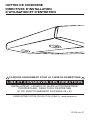
RANGE HOODS
INSTALLATION INSTRUCTIONS — USE AND CARE

WARNING
TO REDUCE THE RISK OF FIRE, ELECTRIC
SHOCK OR INJURY TO PERSONS, OBSERVE
THE FOLLOWING:
1. Use this unit only in the manner intended by the
manufacturer. If you have questions, contact the
manufacturer at the address or telephone number
listed in the warranty.
2. Before servicing or cleaning unit, switch power off
at service panel and lock service disconnecting
means to prevent power from being switched on
accidentally. When the service disconnecting
means cannot be locked, securely fasten a prominent
warning device, such as a tag, to the service panel.
3. Installation work and electrical wiring must be done
by qualified personnel in accordance with all
applicable codes and standards, including
fire-rated construction codes and standards.
4. Sufficient air is needed for proper combustion and
exhausting of gases through the flue (chimney) of
fuel burning equipment to prevent backdrafting.
Follow the heating equipment manufacturer’s
guidelines and safety standards such as those
published by the National Fire Protection
Association (NFPA), and the American Society for
Heating, Refrigeration and Air Conditioning
Engineers (ASHRAE), and the local code authorities.
5. When cutting or drilling into wall or ceiling, do not
damage electrical wiring and other hidden utilities.
6. Ducted fans must always be vented to the outdoors.
7. Do not use this unit with any additional solid-state
speed control device.
8. To reduce the risk of fire, use only metal ductwork.
9.
This unit must be grounded.
10. When applicable local regulations comprise more
restrictive installation and/or certification
requirements, the aforementioned requirements
prevail on those of this document and the installer
agrees to conform to these at his own expenses.
TO REDUCE THE RISK OF A RANGE TOP
GREASE FIRE:
a) Never leave surface units unattended at high
settings. Boilovers cause smoking and greasy
spillovers that may ignite. Heat oils slowly on low or
medium settings.
b) Always turn hood ON when cooking at high heat or
when flambeing food (i.e.: Crêpes Suzette,
Cherries Jubilee, Peppercorn Beef Flambé).
c) Clean ventilating fans frequently. Grease should
not be allowed to accumulate on fans, filters or
exhaust ducts.
d) Use proper pan size. Always use cookware
appropriate for the size of the surface element.
!
WARNING
TO REDUCE THE RISK OF INJURY TO PERSONS
IN THE EVENT OF A RANGE TOP GREASE
FIRE, OBSERVE THE FOLLOWING*:
1. SMOTHER FLAMES with a close-fitting lid,
cookie sheet or metal tray, then turn off the burner.
BE CAREFUL TO PREVENT BURNS. IF THE
FLAMES DO NOT GO OUT IMMEDIATELY,
EVACUATE AND CALL THE FIRE DEPARTMENT.
2. NEVER PICK UP A FLAMING PAN – You may be
burned.
3. DO NOT USE WATER, including wet dishcloths
or towels – This could cause a violent steam
explosion.
4. Use an extinguisher ONLY if:
A. You own a Class ABC extinguisher and you
know how to operate it.
B. The fire is small and contained in the area
where it started.
C. The fire department has been called.
D. You can fight the fire with your back to an exit.
*Based on “Kitchen Fire Safety Tips” published by NFPA.
!
- 2 -
CAUTION
1. For indoor use only
2. For general ventilating use only. Do not use to
exhaust hazardous or explosive materials and
vapors.
3. To avoid motor bearing damage and noisy and/or
unbalanced impeller, keep drywall spray, construction
dust, etc. off power unit.
4. Your hood motor has a thermal overload which will
automatically shut off the motor if it becomes
overheated. The motor will restart when it will cool
down. If the motor continues to shut off and restart,
have the hood serviced.
5. The minimum hood distance above cooktop must
not be less than 20” for an electric range, and 24”
for a gas range. A maximum of 30” above cooktop
is highly recommended for best capture of cooking
impurities.
6. Two installers are recommended because of the
large size and weight of this hood.
7. To reduce the risk of fire and to properly exhaust
air, be sure to duct air outside – Do not exhaust air
into spaces within walls or ceiling or into attics,
crawl space or garage.
8. Refer to the specification label on product to see if
this unit is equipped with a thermostat which may
start blower automatically. In this case, to reduce
the risk of injury and to prevent power from being
switched on accidentally, switch power off at
service panel and lock or tag service panel.
9. Because of the high exhausting capacity of this
hood, you should make sure enough air is entering
the house to replace exhausted air by opening a
window close to or in the kitchen.
10. Use with approved cord-connection kit only.
11. Please read specification label on product for
further information and requirements.
12. All demonstrator range hoods (model numbers
ending by D) are not for sale, unless their original
power cord is removed.

Because of the large amount of models covered by this publication, the illustrations are typical
ones. Some details of your unit may be slightly different of the ones shown.
Please take note this manual uses the following symbols to emphasize particular information:
NOTE: Indicates supplementary information needed to fully complete an instruction.
A single blower range hood can be installed either with an exterior outlet or not.
If a single blower range hood is not installed with an exterior outlet, a charcoal filter module must
be installed (sold separately).
This module must be installed prior to proceed to the hood installation. Refer to the installation
sheet included in the charcoal filter module kit.
ABOUT THIS MANUAL
HOOD INSTALLED WITH A CHARCOAL FILTER MODULE
CAUTION
Denotes an instruction which, if not followed, may severely damage the unit
and/or its components.
Identifies an instruction which, if not followed, might cause serious personal
injuries including possibility of death.
WARNING
!
CAUTION
All dual blower range hoods must always be installed with an exterior outlet.
Never install a charcoal filter module with those specific range hoods.
TOOLS NEEDED TO INSTALL THE RANGE HOOD
- Phillips screwdriver no. 2 or Robertson no. 1 and no. 2
- Pair of long nose pliers (to open the horizontal or vertical discharge knockout hole)
- Hammer and flat blade screwdriver (to open the electrical knockout hole)
- Sheet metal sheers (ducted installation only, for duct adjustment)
- Pair of pliers (ducted installation only, for duct adjustment)
- Scissors (to cut metal foil duct tape)
- Pen
- Wire stripper
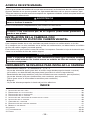
TABLE OF CONTENTS
- 3 -
1. INSTALL DUCTWORK . . . . . . . . . . . . . . . . . . . . . . . . . . . . . . . . . . . . . . . . . . . . . . . . . . . . . . . . . 4
2. MEASURE THE INSTALLATION . . . . . . . . . . . . . . . . . . . . . . . . . . . . . . . . . . . . . . . . . . . . . . . . . . . . 4
3. PREPARE THE INSTALLATION . . . . . . . . . . . . . . . . . . . . . . . . . . . . . . . . . . . . . . . . . . . . . . . . . . . . 5
4. PREPARE THE HOOD . . . . . . . . . . . . . . . . . . . . . . . . . . . . . . . . . . . . . . . . . . . . . . . . . . . . . . . . . 6
5. INSTALL THE ADAPTER/DAMPER . . . . . . . . . . . . . . . . . . . . . . . . . . . . . . . . . . . . . . . . . . . . . . . . . 7
6. INSTALL THE HOOD . . . . . . . . . . . . . . . . . . . . . . . . . . . . . . . . . . . . . . . . . . . . . . . . . . . . . . . . . . 8
7. CONNECT WIRING . . . . . . . . . . . . . . . . . . . . . . . . . . . . . . . . . . . . . . . . . . . . . . . . . . . . . . . . . . . 8
8. REINSTALL BOTTOM PANEL . . . . . . . . . . . . . . . . . . . . . . . . . . . . . . . . . . . . . . . . . . . . . . . . . . . . . 9
9. HALOGEN LIGHT BULBS . . . . . . . . . . . . . . . . . . . . . . . . . . . . . . . . . . . . . . . . . . . . . . . . . . . . . . . 9
10. CARE . . . . . . . . . . . . . . . . . . . . . . . . . . . . . . . . . . . . . . . . . . . . . . . . . . . . . . . . . . . . . . . . 10-11
11. OPERATION . . . . . . . . . . . . . . . . . . . . . . . . . . . . . . . . . . . . . . . . . . . . . . . . . . . . . . . . . . . . 11-14
12. S
ERVICE PARTS . . . . . . . . . . . . . . . . . . . . . . . . . . . . . . . . . . . . . . . . . . . . . . . . . . . . . . . . . 15-16

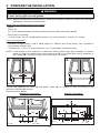
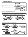
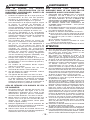
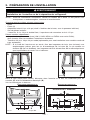
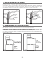
1. INSTALL DUCTWORK
Plan where and how the ductwork will be installed.
Install proper-sized ductwork, elbow(s) and roof or wall cap for the type of blower you are installing.
If using 6” round ducts, use a transition. Use 2” metal foil duct tape to seal duct joints.
Hood
3¼” x 10” duct
Roof cap
Wall cap
HH0011A
Hood
6” round duct
Roof cap
Wall cap
3¼” x 10” to 6”
round transition
HH0014A
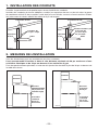
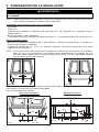
2. MEASURE THE INSTALLATION
Dimensions for the most common installations are shown below.
We recommend to install the hood at a minimum distance of 20” from an electric range and
at 24” from a gas range.
For optimal performance, the hood should not be installed more than 30” from cooktop.
Cabinets
30” maximum
clearance
Standard
36” height
cooktop
HH0012A
Hood
Cabinets
20” minimum
clearance
(24” for gas)
Standard
36” height
cooktop
HH0013A
Hood
- 4 -

3. PREPARE THE INSTALLATION
Make sure the following items are included:
- Hood
- Filters (2)
- 3¼’’ x 10’’ Adapter/damper (located inside the hood, under the bottom panel)
- Bag of parts including:
(1) wire clamp, (5) 1/2’’ double thread screws, (2) wire connectors and (6) 1/2’’ screws
Parts sold separately
:
- Shielded halogen lamps (120 V, 50 W, MR16 or PAR16 with GU10 base), two included in
Connaisseur models only
- Transition 3¼” x 10” to 6” round (optional, for 6” round ducts installation only)
NOTE: Before proceeding to the installation, check the contents of the box. If items are missing or
damaged, contact the manufacturer.
When performing installation, servicing or cleaning the unit, it is recommended
to wear safety glasses and gloves.
WARNING
!
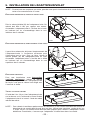
NOTE: If the bottom of the cupboard is recessed, attach wood strips (not included), as shown
below, in order to properly install the range hood (A) or charcoal filter unit (if need be) to
the cabinet (B). The wood strips must be as thick as recess.
HO0002A
2 ”
3
8
HD0033
A
B
Cut-out the openings for duct (A) and power cable (B), in cabinet or wall, according to the
direction of discharge chosen.
See illustrations below.
HORIZONTAL DISCHARGE: VERTICAL DISCHARGE:
C
L
HD0150A
3½”
5¼” 5¼”
B
1¼” dia.
A
7
8
”
11
1
8
”
C
L
¾”
3¾”
5¼” 5¼”
1 ¼”
HD0151A
A
CABINET BOTTOM
B
3
8
”
1½”
10½”
- 5 -

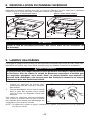
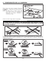
4. PREPARE THE HOOD
Remove both filters from the hood.
Disassemble the adapter/damper (A) from the
hood.
NOTE: The bottom panel (B) must be removed
to access the adapter/damper.
HO0055
A
B
Punch out the appropriate electrical knock-out hole.
CAUTION
Never use a hammer and a screwdriver to punch out the vertical or horizontal
discharge knock-out, because this will damage the hood internal parts.
HD0152
Using a long nose pliers, remove the knock-outs for the chosen opening (vertical on top or
horizontal at the back of the hood). See illustrations below.
1
2 3
HR0018
1 2 3
VERTICAL
DISCHARGE
HORIZONTAL
DISCHARGE
- 6 -

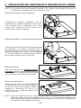
NOTE: If this hood replaces another one, please note that the location of the air exhaust can vary
from one manufacturer to another.
5. INSTALL THE ADAPTER/DAMPER
Fold down the adapter/damper foldable flange (C).
This flange must be at 90° from the remaining
flanges. Use the lower screw holes on each side of
the adapter/damper to assemble it to the back of
hood.
HJ0006
C
It may be necessary to adjust the adapter/damper
location to the existing wall discharge opening.
Leave the adapter/damper foldable flange (C) as is.
Use the upper screw holes on each side of the
adapter/damper to assemble it to the back of hood.
HJ0007
C
HORIZONTAL DISCHARGE, NEW INSTALLATION
HORIZONTAL DISCHARGE, HOOD REPLACEMENT
- 7 -
VERTICAL DISCHARGE
For a vertical discharge installation only,
leave the adapter/damper foldable flange (C)
as is. This flange must be located towards the
front of the hood.
HO0057
C
NOTE: For the best ventilation performance, if a round duct must be used, the duct diameter must
be 6” or more. Use a 3¼” x 10” to 6” round transition. The wall duct must be well prepared
to receive the adapter. Before performing the installation, make sure the adapter fits easily
in the duct.
A
LL INSTALLATIONS
Using two 1/2” screws, secure the
adapter/damper to the top or back of the
hood. Tape the adapter/damper to the hood
using metal foil duct tape to seal it.
HO0058

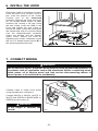
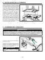
6. INSTALL THE HOOD
Run power cable to installation location.
Place the hood at its location. Using a
pen, mark the position of the screws
(smaller part of the embossed
keyholes). Remove the hood and install
(4) 1/2” double thread screws at sides
locations (A), leaving a 1/8” gap. Place
the wire clamp, insert the cable in the
hood and tighten the wire clamp to
secure the cable. Place the hood under
the cabinet and slide it in position. Make
sure the adapter/damper assembly
enters the ducting and the damper
opens freely. Secure the hood by
tightening the screws completely. Install
the last 1/2” double thread screw (B) in
the remaining embossed hole.
HD0154
A
A
B
WARNING
Risk of electrical shock. Electrical wiring must be done by qualified personnel in
accordance with all applicable codes and standards. Before connecting wires,
switch power off at service panel and lock service disconnecting means to
prevent power to be switched on accidentally.
!
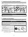
7. CONNECT WIRING
- 8 -
Connect cable to range hood wiring
using included wire connectors.
Connect BLACK to BLACK, WHITE to
WHITE and GREEN or BARE WIRE to
GREEN ground screw (1).
HE0059
1
WARNING
Do not forget to connect the
ground!
!

CAUTION
Remove protective plastic film covering filters before reinstalling them (if need be).
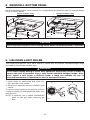
8. REINSTALL BOTTOM PANEL
Reinstall the bottom panel, using 5 screws for a single blower hood and 6 screws for a double blower
hood, as shown below.
SINGLE BLOWER HOOD DOUBLE BLOWER HOOD
Then, reinstall filters.
HO0059
HO0066
- 9 -
9. HALOGEN LIGHT BULBS
This range hood requires 120 V, 50 W, MR16 or PAR16 with GU10 base, shielded halogen lamps
(included in Connaisseur models only).
WARNING
!
Do not touch lamps during or soon after operation. Burns may occur. In order to
prevent the risk of personal injury, only install shielded halogen lamps. Also,
never install a cool beam, a dichroic lamp, a lamp not suitable for use in
recessed luminaires or identified for use in enclosed fixtures.
1. Install lamps by placing the bulb leads into
their grooves in the socket.
2. Gently push upwards and turn clockwise until
secure.
To remove lamps, gently push upwards and turn
counterclockwise to disengage bulb leads from
their grooves.
NOTE: If need be, use a rubber dishwashing
glove to add grip when removing the
bulb.
12
HO0090

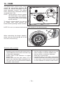
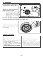
10. CARE
The grease filters, bottom panel, intake
ring(s) (A) and blower wheel(s) (B)
should be cleaned frequently. Use a
warm detergent solution. The grease
filters, intake ring(s) and blower wheel(s)
are dishwasher safe.
NOTE: Some minerals, when in contact
with dishwasher soap additives,
may cause filters discoloration.
This discoloration is not covered
by the warranty.
To remove a blower wheel, first take off
its intake ring. Then remove the
blower wheel by pulling it down smoothly.
NOTE: Do not try to remove the black part (C) attached to the bottom panel.
When reinstalling the blower wheel(s),
make sure the small tab (D) will fit into
one hole of the motor(s).
HD0155
A
B
C
HD0156
- 10 -
D
STAINLESS STEEL CLEANING:
Do:
• Regularly wash surfaces with clean cloth or
rag soaked with warm water and mild soap
or liquid dish detergent.
• Always clean in the direction of original
polish lines.
• Always rinse well with clear water (2 or 3
times) after cleaning. Wipe completely dry.
• You may also use a specialized household
stainless steel cleaner.
Don’t:
• Use any steel or stainless steel wool or any
other scrapers to remove stubborn dirt.
• Use any harsh or abrasive cleansers.
• Allow dirt to accumulate.
• Let plaster dust or any other construction
residues reach the hood. During construction
or renovation, cover the hood to make sure
no dust adheres to stainless steel surface.

10. CARE (CONT’D)
Avoid when choosing a detergent:
- Any cleaners that contain bleach will attack stainless steel.
- Any products containing: Chloride, fluoride, iodide, bromide will deteriorate surfaces rapidly.
-Any combustible products used for cleaning such as acetone, alcohol, ether, benzol, etc.,
are highly explosive and should never be used close to a range.
ENAMEL FINISH:
Clean with warm water and mild detergent only. If discoloration occurs, use a good enamel polish
such as automotive polish. (DO NOT use rough abrasive cleaner or porcelain cleaner.)
- 11 -
11. OPERATION
Always turn on the hood before begining cooking in order to establish an air flow in the kitchen. Let
the blower(s) run for a few minutes to clear the air after turning off the range.
Following are all the controls used by the hood models covered in this manual. Identify the one
installed on your hood and see how to operate it.
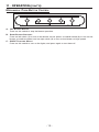
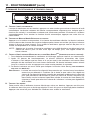
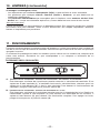
ROCKER SWITCH CONTROL
A. ON/OFF BLOWER AND SPEED CONTROL SWITCH:
This 3-position rocker switch controls the blower speed. Pressing on left side (1) will result in
low speed operation, while pressing on right side (2) will turn on the blower to high speed. To
stop the blower operation, set the rocker switch to the central position (0).
B. ON/OFF L
IGHTING INTENSITY CONTROL SWITCH:
This 3-position rocker switch controls the lighting level. According to your needs, press on left
side (1) to get nightlight intensity, or press on right side (2) to obtain full lighting. To shut off the
lights, set the rocker switch to the central position (0).
HC0020
A
B

- 12 -
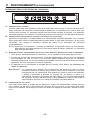
MECHANICAL PUSH-BUTTON CONTROL
A. OFF BLOWER SWITCH:
Press on this switch to stop the blower operation.
B. SPEED BLOWER SWITCHES:
Press on left switch (1) to turn on the blower on low speed, on middle switch (2) to turn on the
blower on medium speed, and on right switch (3) to turn on the blower on high speed.
C. ON/OFF LIGHTING SWITCH:
Press on this switch to turn on the lights, and press again to turn them off.
HC0021
A
BC
11. OPERATION (CONT’D)

11. OPERATION (CONT’D)
- 13 -
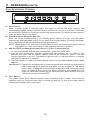
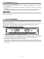
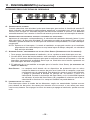
OVAL ELECTRONIC CONTROL
A. DELAY SWITCH:
When a blower speed is selected, press this switch to activate the delay function. The
corresponding speed indicator light will flash to indicate this function is activated. The blower
will continue to operate for 5 minutes and will stop automatically. To cancel the delay function,
press the delay switch once again.
B. START/STOP/SPEED SELECTION SWITCHES:
Press the switch corresponding to the desired blower speed. The light over the switch
indicates the selected speed (from 1 for low speed to 4 for high speed). To turn off the blower,
press once more on the corresponding blower speed switch.
NOTE: When blower is off, pressing on blower speed 1 switch will cause the blower to start on
high speed for a very short lapse of time, and then resume on speed 1.
C. MASTER OFF/FILTER MAINTENANCE/HEAT SENTRY™ (TRIPLE FUNCTION SWITCH):
i. To turn off the blower and the light simultaneously, press the switch once.
ii. After 25 hours of operation, the filter maintenance light indicator will turn itself on. This
indicates the filters and the blower wheel(s) need to be cleaned in order to maintain
efficient operation of the unit. The indicator light will stay on until the function is reset by
pressing this switch for 3 seconds.
iii. The light indicator is used for the Heat Sentry function as well (NOT AVAILABLE ON ALL HOOD
MODELS).
HEAT SENTRY™:The hood is equipped with a protective device that activates when excessive
heat is detected inside the hood and when it is set on speed 4. This device
takes control of the blower and deactivates speed 4 for a 10-minute period and
sets it on speed 3. During the Heat Sentry activation, only speed 3 can be
used; the Heat Sentry button (C) will flash while the speed 3 button will light.
The hood can also be turned OFF.
D. LIGHT SWITCH:
This switch allows three different lighting levels according to your needs. Press once for
nightlight, twice for normal or three times to obtain full intensity. To shut off the lights without
turning off the blower, press once more.
HC0022
A
BC D

ROUND ELECTRONIC CONTROL
A. DELAY SWITCH:
When a blower speed is selected, press this switch to activate the delay function. The
corresponding blower speed switch will flash to indicate this function is activated. The blower
will continue to operate for 5 minutes and will stop automatically. To cancel the delay function,
press the delay switch once again.
B. START/STOP/SPEED SELECTION SWITCHES:
Press the switch corresponding to the desired blower speed (from 1 for low speed to 4 for high
speed). The chosen switch will light. To turn off the blower, press once more on the
corresponding blower speed switch; the switch light will shut off.
NOTE: When blower is off, pressing on blower speed 1 switch will cause the blower to start on
high speed for a very short lapse of time, and then resume on speed 1.
C. MASTER OFF/FILTER MAINTENANCE/HEAT SENTRY (TRIPLE FUNCTION SWITCH):
i. To turn off the blower and the light simultaneously, press this switch once.
ii. After 25 hours of operation, this switch will light to indicate the filters and the blower wheel(s)
need to be cleaned in order to maintain efficient operation of the unit. The switch light will
stay on until the function is reset by pressing this switch for 3 seconds.
iii. The light indicator is used for the Heat Sentry function as well (NOT AVAILABLE ON ALL HOOD
MODELS).
H
EAT SENTRY™:The hood is equipped with a protective device that activates when excessive
heat is detected inside the hood and when it is set on speed 4. This device
takes control of the blower and deactivates speed 4 for a 10-minute period and
sets it on speed 3. During the Heat Sentry activation, only speed 3 can be
used; the Heat Sentry button (C) will flash while the speed 3 button will light.
The hood can also be turned OFF.
D. L
IGHT SWITCH:
This switch allows three different lighting levels according to your needs. Press once for
nightlight, twice for normal or three times to obtain full intensity. To shut off the lights without
turning off the blower, press once more.
HC0023
A
BCD
11. OPERATION (CONT’D)
- 14 -
Page is loading ...

- 16 -
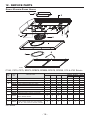
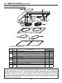
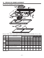
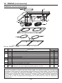
DOUBLE BLOWER RANGE HOODS
HL0062
1
3
2
5
6
5
3
4
4
7
7
C600E & V40E SERIES
*Not shown.
KEY
NO.
PART
NO.
DESCRIPTION
QTY. PER SERIES
C600E V40E
1 13296 ADAPTER/DAMPER 1 1
2 16153 SMOKED GLASS 1 -
3
16150 GLASS HOLDER BLACK (THE PAIR) 1 -
16151 GLASS HOLDER WHITE (THE PAIR) 1 -
16152 GLASS HOLDER GREY (THE PAIR) 1 -
4 01988 BLOWER WHEEL 2 2
5 01757 INLET RING 2 2
6
14131 MICROMESH FILTERS (THE PAIR) - 1
06941 STAINLESS STEEL FILTERS (THE PAIR) 1 -
7 05921 SHIELDED HALOGEN BULBS 120 V, 50 W, GU10 2 -
* 07020 INSTALLATION AND USER MANUAL 1 1
* 04281
HARDWARE BAG: 2 WIRE CONNECTORS, 1 WIRE CLAMP,
6
NO. 6 X 1/2” SCREWS, 5 NO. 8 X 1/2” DOUBLE THREAD SCREWS
1 1
REPLACEMENT PARTS AND REPAIRS
In order to ensure your unit remains in good working condition, you must use the manufacturer
genuine replacement parts only. The manufacturer genuine replacement parts are specially
designed for each unit and are manufactured to comply with all the applicable certification
standards and maintain a high standard of safety. Any third party replacement part used may
cause serious damage and drastically reduce the performance level of your unit, which will result
in premature failing. The manufacturer recommends to contact a certified service depot for all
replacement parts and repairs.
12. SERVICE PARTS (CONT’D)

07020 rév. 07
CONÇUES UNIQUEMENT POUR LA CUISSON DOMESTIQUE
INSTALLATEUR : LAISSEZ CE GUIDE AU PROPRIÉTAIRE.
PROPRIÉTAIRE : DIRECTIVES D’ENTRETIEN
ET DE FONCTIONNEMENT EN PAGES 26
À 30.
LIRE ET CONSERVER CES DIRECTIVES
!
!
HOTTES DE CUISINIÈRE
DIRECTIVES D’INSTALLATION,
D’UTILISATION ET D’ENTRETIEN
ENREGISTREZ VOTRE PRODUIT EN LIGNE À : www.venmar.ca
Page is loading ...
Page is loading ...
Page is loading ...
Page is loading ...
Page is loading ...
Page is loading ...
Page is loading ...
Page is loading ...
Page is loading ...
Page is loading ...
Page is loading ...
Page is loading ...
Page is loading ...
Page is loading ...
Page is loading ...

07020 rev. 07
EXCLUSIVAMENTE PARA COCINAS DOMÉSTICAS
INSTALADOR: ENTREGUE ESTE MANUAL AL PROPIETARIO DE LA CASA.
PROPIETARIO: INFORMACIÓN SOBRE LIMPEIZA Y FUNCIONAMIENTO
EN LAS PÁGINAS 42
A 46.
LEA Y CONSERVE ESTAS INSTRUCCIONES
!
!
REGISTRE SU PRODUCTO EN LÍNEA EN: www.venmar.ca
CAMPANAS DE COCINA
INSTRUCCIONES DE INSTALACIÓN -
UTILIZACIÓN Y CUIDADO
Page is loading ...
Page is loading ...
Page is loading ...
Page is loading ...
Page is loading ...
Page is loading ...
Page is loading ...
Page is loading ...
Page is loading ...
Page is loading ...
Page is loading ...
Page is loading ...
Page is loading ...

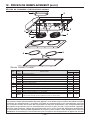
12. PIEZAS
CAMPANAS CON UNO VENTILADOR
HL
006
1
1
3
2
5
6
3
4
7
7
SERIES C180, C270, C370, ED370, ROB15, ROB35, ROV15, ROV35, V10 Y V30
*No se muestra.
N.° DE
REF.
N.° DE
PIEZA
DESCRIPCIÓN
CANTIDAD POR SERIE
C180 C270 C370 ED370
ROB15 ROV15 V10
ROB35 ROV35 V30
1 13296 ADAPTADOR, DISPOSITIVO DE CIERRE 1 1 1 1 1 1 1
2 16153 CRISTAL HUMADO 1 1 1 1 - - -
3
16150 SOPORTE DE CRISTAL NEGRO (PA R ) 1 1 1 1 - - -
16151 SOPORTE DE CRISTAL BLANCO (PAR ) 1 1 1 1 - - -
16152 SOPORTE DE CRISTAL GRIS (PAR ) 1 1 1 1 - - -
4 01988 RUEDA DEL VENTILADOR 1 1 1 1 1 1 1
5 01757 ANILLO DE ENTRADA 1 1 1 1 1 1 1
6
14131 FILTROS DE MICROTAMIZ (PA R) 1 1 - - 1 1 1
06941 FILTROS DE ACERO INOXIDABLE (PAR ) - - 1 1 - - -
7 05921
BOMBILLAS HALOGENAS PROTEGIDAS
120 V, 50 W, GU10
222- - - -
* 07020 MANUAL DE INSTALACIÓN Y DEL USUARIO 1 1 1 1 1 1 1
* 04281
BOLSA CON PIEZAS METÁLICAS:
2
CONECTADORES DE HILO,
1
ABRAZADERA DE CABLE,
6
TORNILLOS N.° 6 X 1/2”,
5
TORNILLOS DE ROSCA DOBLE N.° 8 X 1/2”
1 1 1 1 1 1 1
- 47 -

- 48 -
CAMPANAS CON DOS VENTILADORES
HL0062
1
3
2
5
6
5
3
4
4
7
7
SERIES C600E Y V40E
*No se muestra.
N.° DE
REF
.
N.° DE
PIEZA
DESCRIPCIÓN
CANT. POR SERIE
C600E V40E
1 13296 ADAPTADOR, DISPOSITIVO DE CIERRE 1 1
2 16153 CRISTAL HUMADO 1 -
3
16150 SOPORTE DE CRISTAL NEGRO (PAR ) 1 -
16151 SOPORTE DE CRISTAL BLANCO (PA R) 1 -
16152 SOPORTE DE CRISTAL GRIS (PA R) 1 -
4 01988 RUEDA DEL VENTILADOR 2 2
5 01757 ANILLO DE ENTRADA 2 2
6
14131 FILTROS DE MICROTAMIZ (PA R) - 1
06941 FILTROS DE ACERO INOXIDABLE (PA R) 1 -
7 05921 BOMBILLAS HALOGENAS PROTEGIDAS 120 V, 50 W, GU10 2 -
* 07020 MANUAL DE INSTALACIÓN Y DEL USUARIO 1 1
* 04281
BOLSA CON PIEZAS METÁLICAS: 2 CONECTADORES DE HILO, 1 ABRAZADERA DE CABLE,
6
TORNILLOS N.° 6 X 1/2”, 5 TORNILLOS DE ROSCA DOBLE N.° 8 X 1/2”
1 1
SUSTITUCIÓN DE PIEZAS Y REPARACIÓN:
Para que la unidad se conserve en buen estado, debe usar repuestos genuinos del fabricante
únicamente. Estas piezas se han diseñado especialmente para cada unidad y se han fabricado
conforme a las normas de certificación aplicables y un elevado nivel de seguridad. El uso de
repuestos de otros fabricantes podría causar daños graves y reducir radicalmente el desempeño
de la unidad, causando así fallas prematuras. El fabricante también aconseja ponerse en
contacto con un taller de reparación homologado por el fabricante para todos los repuestos y
reparaciones.
12. PIEZAS (CONTINUACIÓN)
-
 1
1
-
 2
2
-
 3
3
-
 4
4
-
 5
5
-
 6
6
-
 7
7
-
 8
8
-
 9
9
-
 10
10
-
 11
11
-
 12
12
-
 13
13
-
 14
14
-
 15
15
-
 16
16
-
 17
17
-
 18
18
-
 19
19
-
 20
20
-
 21
21
-
 22
22
-
 23
23
-
 24
24
-
 25
25
-
 26
26
-
 27
27
-
 28
28
-
 29
29
-
 30
30
-
 31
31
-
 32
32
-
 33
33
-
 34
34
-
 35
35
-
 36
36
-
 37
37
-
 38
38
-
 39
39
-
 40
40
-
 41
41
-
 42
42
-
 43
43
-
 44
44
-
 45
45
-
 46
46
-
 47
47
-
 48
48


Ask a question and I''ll find the answer in the document
Finding information in a document is now easier with AI
in other languages
- français: Venmar ROV15 Manuel utilisateur
- español: Venmar ROV15 Manual de usuario


