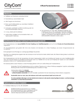
Kathrein UAS 584 User manual

Category
Satellite antennas
Type
User manual

The Kathrein UAS 584 is a universal Quatro feed system designed for Kathrein offset parabolic antennas, suitable for receiving satellites in the Ku band, such as ASTRA, EUTELSAT, or TürkSat. It complies with ASTRA specifications for universal SMATV systems and features a compact design for multifeed capability. The complete LNB and cable connections are protected by the IP 54 certified ventilated housing.

The Kathrein UAS 584 is a universal Quatro feed system designed for Kathrein offset parabolic antennas, suitable for receiving satellites in the Ku band, such as ASTRA, EUTELSAT, or TürkSat. It complies with ASTRA specifications for universal SMATV systems and features a compact design for multifeed capability. The complete LNB and cable connections are protected by the IP 54 certified ventilated housing.

Universal-Quatro-Speisesystem (4 Ausgänge) für Kathrein-
Offset-Parabolantennen, Typ CAS ... (60, 75, 90, 120 cm Ø)
Für den Empfang von Satelliten im Ku-Band, wie z. B. ASTRA,
EUTELSAT oder TürkSat
Das Speisesystem entspricht der ASTRA-Spezi kation für
Universal-SMATV-Systeme
Stromversorgung erfolgt über Niederführungskabel
Multifeed-tauglich durch kompakten Aufbau
Komplettschutz von LNB und Kabelanschlüssen im belüfteten
Gehäuse, Schutzart: IP 54
Universal Quatro feed system (4 outputs) für Kathrein offset parabolic
antennas, type CAS.. (60, 75, 90, 120 cm Ø)
For reception of satellites in the Ku band, such as ASTRA,
EUTELSAT and TürkSat
The feed system complies with ASTRA speci cations for universal SMATV systems
Power supply via drop cable
Multifeed-suitable due to compact design
Full protection of LNB and cable connections in a ventilated housing, protection category IP 54
Système d’alimentation Quatro universel pour antennes paraboliques (4 sorties) offset Kathrein type CAS.. (60, 75, 90,
120 cm Ø)
Pour la réception des satellites dans la bande Ku, comme ASTRA, EUTELSAT ou TürkSat.
Le système d’alimentation est conforme à la spéci cation ASTRA pour les systèmes universels SMATV
Alimentation électrique par câble descendant
Possibilité de réception Multifeed grâce à la compacité du système
Protection complète du LNB et des branchements dans un boîtier ventilé du type de protection : IP 54
Universal-Quatro-Speisesystem
Universal Quatro feed system
Universal-Tête SHF Quatro
UAS 584
20110019
10,70-12,75 GHz
936.3190/A/1008/1.8d/e/f
Hinweise/Notes/Remarques
Das Speisesystem UAS 584 darf ausschließlich an die aufgeführten Kathrein-Parabolantennen montiert werden.
Für das Speisesystem gelten die gleichen Sicherheits- und Gefahrenhinweise, wie sie in den Anwendungshinweisen
der Offset-Parabolantennen aufgeführt sind. Bitte beachten Sie unbedingt diese Hinweise, da sonst Gefahren für Sie
oder Ihre Mitmenschen auftreten können (Stromschlag durch Freileitungen, Absturzgefahr, herabfallende Teile,
Gewitter etc.)
The UAS 584 feed system may only be mounted to the listed Kathrein parabolic antennas. The feed system is subject to the
same safety and danger warnings as listed in the instructions for using offset parabolic antennas. Please follow these instruc-
tions at all times, as otherwise you or other people may be exposed to danger (electric shock through overhead lines, risk of
falling down, falling parts, thunderstorm etc.)
Le système d’alimentation UAS 584 ne doit être monté que sur les antennes paraboliques Kathrein. En ce qui concerne le sys-
tème d’alimentation, les instructions de danger et de sécurité appliquées sont identiques à celles décrites dans les instructions
d’utilisation desantennes paraboliques Offset.Veuillez suivre scrupuleusement ces instructions, sinon vous risqueriez de vous
mettre vous-même en danger ou d‘autres personnes (décharge électrique due à des câbles aériens, risque de chute, pièces
risquant de se détacher, orage etc.)
936.3190/A/1008/3.8def
Speisesystem-Montage (Abb. 1)
Mounting the feed system (Fig. 1)
Montage de la système d´alimentation (Fig. 1)
Abb. 1/Fig. 1
Polarisations-Voreinstellung (Abb. 2)
Setting the polarisation (Fig. 2)
Ajustage de la polarisation (Fig. 2)
Wert für die Polarisations-Voreinstellung aus Tabelle Seite 7
entnehmen. Bei abweichendem Wert von den voreingestellten 0°
ist wie folgt zu verfahren:
1. Beide Innensechskantschrauben (S) lockern.
2. Durch Drehen des Speisesystems die Referenzmarke auf den
Wert lt. Polarisations-Voreinstellungs-Tabelle einstellen
(siehe Abb. 2)
3. Die Innensechskantschrauben (S) gleichmäßig im Wechsel
festziehen. Anzugsdrehmoment: Max. 4,5 Nm
See the value in the table on page 7 for the polarisation setting. If the
value differs from the pre-set 0°, proceed as follows:
1. Loosen both Allen screws (S).
2. Turn the feed system to set the reference mark to the value given
in the polarisation pre-setting table. (see g. 2)
3. Tighten the Allen screws (S) evenly, alternating between both.
Torque: max. 4.5 Nm
Relever la valeur d’ajustage de polarisation du tableau en page 7.
Au cas où la valeur est différente de la valeur préajustée de 0°,
procéder comme suit:
1. Desserrer les deux vis à six pans creux (S).
2. Tourner le système d’alimentation pour régler le repère de
référence sur la valeur indiquée dans le tableau de préréglage de
la polarisation (voir la g. 2)
3. Serrer les vis à six pans creux (S) de manière homogène en
alternance. Couple de serrage : maxi. 4,5 Nm
Abb. 2/Fig. 2
Hier ansetzen
Insert here
Introduire ici
Das Speisesystem an gewünschter Position auf die Multifeed-
Platte am Tragarmende aufsetzen (siehe Anwendungs-hinweis
Antenne) und durch anziehen (Anzugsdrehmoment: 4,5 Nm) der
Innensechskantschraube im vorderen Bereich befestigen.
Alle Befestigungs- und Einstelloperationen können mit dem
beigelegten Innensechskantschlüssel (SW4) vorgenommen
werden.
Position the feed system as desired on the multifeed plate at the end
of the bracket (see antenna instructions) and fasten on the front part
using the Allen wrench (torque: 4.5 Nm) .
All fastening and tightening can be effected with the supplied Allen
wrench (SW4).
Placer le système d’alimentation à la position souhaitée sur la
plaque Multifeed à l’extrémité du bras support (voir les instructions
d’utilisation de l’antenne) et le xer en serrant (couple de serrage :
4,5 Nm) la vis à six pans creux à l’avant.
Toutes les opérations de xation et de réglage peuvent être
effectuées à l’aide de la clé de 4 jointe.
Innensechskant-
Schraube (S)
Allen screw
Vis à six pans
Polarisation 0°
Polarisation +15°
Polarisation -15°
M
A
= 4,5 Nm
Abb. 3/Fig. 3
936.3190/A/1008/4.8def
Innensechskant-
Schraube (S)
Allen screw
Vis à six pans
4x
Kabelanschluss (Abb. 3)
1. Innensechskantschraube (S) am hinteren Ende der Haube
lösen, bis die Haube durch leichten Druck nach unten
ausrastet und abgenommen werden kann
.
Cable connection (Fig. 3)
Raccordement de câbles (Fig. 3)
2. Beiliegende F-Stecker auf Kathrein-Kabeltyp LCD 95, 99 oder
111 montieren (siehe Abbildung).
3. Beim Verbinden von LNB und Matrix die korrekte
Zuordnung der Anschlussbelegungen beachten (ggf. Kabel
kennzeichnen).
4. Angeschlossene Kabel nach vorne führen und seitlich
in den Kabelhalter (siehe Vergrößerung in Abb. 3 unten)
eindrücken.
5. Haube aufschieben, bis sie in die Nut eintaucht und im
unteren Bereich einrastet. Innensechskantschraube (S)
festziehen.
Hinweis:
Wird nicht nur das Speisesystem ausgetauscht, sondern eine Neu-
installation der Antenne vorgenommen, fahren Sie zuerst mit dem
Punkt „Ausrichten der Satelliten-Empfangsanlage“ fort und kehren im
Anschluss zum Punkt „Kabelanschluss“ zurück.
1. Loosen the Allen screws (S) at the rear end of the cover until
the cover can be unlocked by applying light downward pressure;
remove cover.
2. Mount the supplied F-type plug onto the Kathrein cable types
LCD 95, 99 or 111 (see gure) and connect to the LNB.
3. When connecting the matrix and the LNB, make sure the correct
output is assigned (mark cables if necessary).
4. Lead the connected cable forwards and insert sideways into the
cable fastening (see close-up in g. 3 below).
5. Slide on the cover until it ts into the groove and locks in the
bottom section. Tighten Allen screw (S).
Note:
If the feed system is not only exchanged but a new antenna system
is being installed, proceed rst as described in the section “Aligning
the satellite reception system” and then return to “Cable connection”.
1. Desserrer la vis à six pans creux (S) à l’extrémité arrière du
capot jusqu’à ce que celui-ci puisse être déverrouillé d’une légère
pression vers le bas et retiré.
2. Monter les connecteurs F joints sur le câble Kathrein type LCD
95, 99 ou 111 (voir la gure) et les raccorder au LNB.
3. En reliant le LNB avec la matrice, s’assurer de la bonne
correspondance des sorties (éventuellement marquez les
câbles).
4. Amener les câbles raccordés vers l’avant et les enfoncer
latéralement dans le support de câbles (voir l’agrandissement au
bas de la g. 3).
5. Mettre en place le capot qui doit entrer dans la gorge et
s’enclencher au bas. Serrer la vis à six pans creux (S).
Remarque:
Si le système d’alimentation est remplacé et qu’une nouvelle installa-
tion de l’antenne est effectuée, poursuivez d’abord par le point «Ori-
entation de l’antenne satellite » puis revenez au point « Branchement
des câbles ».
Ausrichten der Satelliten-Empfangsanlage (Abb. 4)
Hinweis:
Wird lediglich das Speisesystem ausgetauscht, kann das Ausrichten
der Antenne entfallen.
936.3190/A/1008/5.8def
1. Grundeinstellung nach beiliegender Azimut-/Elevationstabelle
vornehmen.
2. Durch Drehen über die Azimut-Achse Sender suchen
(siehe beiliegende Azimut-/Elevationstabelle) und auf
Maximalanzeige einstellen (bei Verwendung eines Kathrein-
Satelliten-Messempfängers MSK ...). Steht kein Messgerät zur
Verfügung, auf beste Bildqualität einstellen (siehe Abb. 5 und
Text).
3. Elevation auf Maximalanzeige bzw. beste Bildqualität
einstellen.
4. Azimut-Einstellung überprüfen und gegebenenfalls
nachjustieren.
5. Alle Befestigungsteile auf vorgeschriebenes Drehmoment MA
festdrehen (siehe Montageanleitung der Parabolantenne).
6. Fahren Sie mit dem Punkt “Kabelanschluss,
(Aufzählungspunkt 2)” fort.
Aligning the satellite reception system (Fig. 4)
Note:
If the feed system is only to be exchanged, the antenna does not
have to be aligned.
1. Align according to enclosed azimuth/elevation table.
2. Tune to wanted programme (see enclosed azimuth/elevations
table) by turning the antenne around the azimuth axle until max.
signal level is obtained (if a Kathrein signal meter MSK.. is used),
or until best picture quality is reached (without signal meter) (see
Fig. 5).
3. Adjust elevation until max. signal level or best picture quality are
obtained.
4. Check azimuth adjustment and correct if neccessary.
5. Firmly x all bolts to advised torque moment MA) (see mounting
instructions for parabolic antenna).
6. Continue as described in section “Cable connection” (item 2).
Positionnement de l’antenne satellite (Fig. 4)
Remarque:
Si seul le système d‘alimentation est remplacé, l‘orientation de
l‘antenne est inutile.
1. Procéder à l’alignement de l’antenne selon le tableau Azimut/
Elevation livré avec la tête.
2. Rechercher un programme satellite (voir tableau azimut/élévation
livré avec la tête) en tournant l’antenne autour de son axe Azimut
jusqu’on a trouvé le niveau le plus élévé (en cas d’utilisation d’un
mesureur de champ satellite Kathrein (MSK..) ou jusqu’à l’on a
obtenu la meilleure image (alignement sans mesureur de champ
satellite) (voir Illustr. 5).
3. Ajuster maintenant l’élévation à l’aide du niveau le plus élévé ou
de la meilleure image.
4. Contrôler à nouveau l’ajustage Azimut et réajuster si nécessaire.
5. Serrer tous les éléments de xation conforme au moment
de torque MA prescrit (voir avis de montage pour l’antenne
parabolique).
6. Poursuivez avec le point « Branchement des câbles » (point 2 de
l’énumération)
Abb. 4/Fig. 4
Azimut
Elevation
Azimut
Elevation
Abb./Fig.5
936.3190/A/1008/6.8def
Da die Antennenkeule im Bereich des Maximums nur leicht gekrümmt ist,
ist bei Ausrichtung in diesem Bereich eine gute Bildqualität zu erwarten.
Jedoch kann es aber sein, dass die Antenne links oder rechts „gerade
noch“ auf diesen guten Empfangsbereich ausgerichtet ist.
Schon bei den ersten Schwankungen des Antennen-Standrohres kann die
vermeintlich gute Bildqualität über die steilen Keulen anken abstürzen.
Um dies zu vermeiden, sollte die Empfangsanlage auf Mitte des Pegel-
maximums eingestellt werden.
Zur Einstellung mit Hilfe eines Kathrein-Satelliten-Messempfängers,
wie z. B. MSK 15 oder MSK 200, gehen Sie wie folgt vor:
1
Mitte der Mastschelle markieren
2 Antenne nach links drehen, bis ein Pegelabfall von z. B. 8 dB
(oder Spikes) auftritt. Mastschellen-Markierung auf den Mast
übertragen
3 Antenne nach rechts drehen, bis ein Pegelabfall von 8 dB auftritt.
Mastschellen-Markierung auf den Mast übertragen
4 Dann Mastschellen-Markierung genau in die Mitte der
Mastmarkierungen stellen. So wird die bestmögliche
Empfangssituation erreicht
Für die Elevations-Optimierung ist ebenso zu verfahren.
As the antenna lobe in the maximum range is only slightly curved, an excellent
picture quality can be expected when it is aligned to this range.
However, it may also be that the antenna at the left or right is “only just” aligned
to this excellent reception range.
As soon as the antenna stanchion experiences any vibration the supposed
excellent picture quality can drop off at the steep edge of the lobe.
To avoid this, the reception position should be set to the middle of the maximum
level.
Proceed as follows when conducting the setting-up process using a Kathrein
test receiver such as MSK 15 or MSK 200:
1
Mark the centre of the mast clamp
2 Turn the antenna to the left until the level drops by, e.g. 8 dB
(or spikes occur). Transfer the mast clamp marking to the mast
3 Turn antenna to the right until the level drops by 8 dB.
Transfer the mast clamp marking to the mast.
4 Position the mast clamp marking in the exact centre of the mast markings.
This will ensure that an ideal reception situation is given
Proceed in a similar manner to optimise the elevation.
Etant donné que le lobe de rayonnement de l’antenne n’est que légèrement
incliné au niveau du maximum, la qualité de l’image devrait être satisfaisante.
Il se peut pourtant que l’antenne à gauche ou à droite se trouve « tout juste
encore » orientée sur cette réception.
Dès les premières oscillations du tube de positionnement de l’antenne,
ladite bonne qualité de l’image peut chuter sur les ancs abrupts du lobe de
rayonnement.
Pour éviter ceci, l’installation de réception doit être réglée sur le milieu du
maximum du niveau.
Pour le réglage à l’aide d’un récepteur de mesure satellite Kathrein,
tel que MSK 15 ou MSK 200, procéder comme suit :
1
Marquer le milieu de la cheville du mât
2 Pivoter l’antenne vers la gauche, jusqu’à ce qu’une chute de niveau par ex.
de 8 dB (ou spikes) intervienne. Reporter la marque de la cheville du mât
sur le mât
3 Pivoter l’antenne vers la droite, jusqu’à ce qu’une chute du niveau de 8 dB
intervienne. Reporter la marque de la cheville du mât sur le mât.
4 Puis placer la marque de collier du mât exactement au milieu des marques
du mât. De cette façon la meilleure position possible de réception est
obtenue
Pour optimiser l’élévation, procéder de la même façon.
Polarisations-Voreinstellungen in verschiedenen Ländern für Compact-Speisesysteme
Pre-setting the polarisation for compact feed systems in various countries
Présélection de la polarisation des systèmes d‘alimentation compacts pour différents pays
Satelliten/Satellites/Satellites
Land/Country/Pays
TÜRKSAT
42° Ost
East/Est
ASTRA
(Eurobird 1)
28.2°
Ost
East/Est
ASTRA
19.2°
Ost
East/Est
EUTELSAT
W2
16°
Ost
East/Est
HOTBIRD
13°
Ost
East/Est
EUTELSAT
W1
10°
Ost
East/Est
EUTELSAT
W3A
Ost
East/Est
Thor 2/3
0.8°
West
West/Ouest
Atlantic
Bird 3
West
West/Ouest
Atlantic
Bird 2/
Telecom 2D
West
West/Ouest
Hispasat
1C/1D
30°
West
West/Ouest
Albanien/Albania/L´Albanie -23 -2 8 5 8 11 15 22 26 28/16 41
Belgien/Belgium/La Belgique -27 -11 -5 -9 -7 -5 -2 4 8 10/-2 25
Bulgarien/Bulgaria/Bulgarie -17 4 14 10 13 16 19 25 29 31/19 41
Dänemark/Denmark/Danemark -19 -4 2 -3 -1 1 3 8 11 ´13/1 24
Deutschland/Germany/Allemagne -23 -7 0 -4 -2 0 3 9 12 14´/2 28
Frankreich/France/France -32 -16 -9 -13 -10 -7 -5 3 7 10/-2 27
Finnland/Finland/Finlande -7 6 10 5679121415´/3 21
Griechenland/Greece/Grèce -21 2 14 11 14 18 21 28 32 34/22 46
Großbritannien/Great Britain/La Grande-Bretagne -26 -13 -8 -13 -11 -9 -7 -2 1 3/-9 17
Italien/Italy/L´Italie -29 -10 -1 -4 -1 3 6 15 19 ´22/10 37
Irland/Ireland/L´Irlande -30 -17 -12 -17 -15 -13 -11 -6 -3 0/12 15
Kroatien/Croatia/Croatie -24 -5 4147101720´23/11 36
Liechtenstein/Liechtenstein/Liechtenstein -26 -10 -2 -6 -3 0 2 10 13 `16/4 31
Luxemburg/Luxemburg/Luxembourg -26 -11 -4 -8 -6 -3 -1 6 9 12/0 26
Monaco/Monaco/Monaco -31 -13 -5 -9 -6 -3 0 9 13 ´16/4 32
Niederlande/Netherlands/Les Pays-Bas -25 -10 -4 -8 -6 -4 -1 5 8 10/-2 24
Norwegen/Norway/Norvège -11 26124591012/0 19
Österreich/Austria/L´Autriche -24 -6 2 -2 0 3 6 13 16 ´18/6 32
Polen/Poland/Pologne -17 0725791518
´20/8 31
Portugal/Portugal/Portugal -43 -28 -22 -26 -23 -20 -17 -8 -3 0/-12 24
Rumänien/Romania/Roumanie -16 4 13 9 11 14 17 23 26 28/16 38
Schweden/Sweden/Suède -12 161245911´13/1 21
Schweiz/Switzerland/Suisse -28 -11 -3 -7 -5 -2 1 8 12 ´15/§ 30
Serbien-Montenegro/Serbia and Montenegro/Serbie-Monténégro -21 -1 9 5 8 11 14 21 24 26/14 39
Slowakei/Slovakia/Slovaquie -18 07368111720´22/10 34
Slowenien/Slovenia/Slovénie -24 -5 3 -1 2 5 8 15 18 ´21/9 34
Spanien/Spain/L´Espagne -40 -24 -17 -21 -18 -15 -11 -2 3 ´6/5 29
Tschechien/Czech Republic/Republique Tchéque -21 -4 40257 1316´19/7 31
Ungarn/Hungary/La Hongrie -20 -1 7369111821´23/11 35
Polarisations-Voreinstellungen für Compact-Speisesysteme in verschiedenen europäischen Ländern (Bezugspunkt ist jeweils die geogra sche Mitte des Landes).
Bei Polarisations-Voreinstellungen größer als ± 25° ist das Speisesystem auf den jeweiligen Anschlag einzustellen.
Polarisation-presettings for compact feed systems in various European countries (the geographical centre of each country is the point of reference in each case)
In case of polarisation-presettings exceeding ± 25°, the feed system is to be set to the respective stop.
Préréglage de polarisation pour des systèmes d‘alimentation compacts dans des pays européens differents (le milieu géographique de chaque pays est le point de référence respectif)
Si le préréglage de polarisation est plus de ± 25°, le système doit être réglé à la butée respective
Weitere Länder bzw. Städte in diesen Ländern nden Sie im Internet auf der Kathrein-Homepage unter „www.kathrein.de/de/sat/index.htm“ im Menüpunkt
„Satelliten-Empfangsanlagen/Technische Infos/Azimut/Elevation und Polarisations-Voreinstellung“.
Find more countries or cities on the Kathrein website on the Internet: www.kathrein.de/de/sat/index.htm, under: “satellite reception systems/technical information/azimut/elevation and polarisation-presetting“.
Trouvez d´autres pays ou villes sur notre page dans l´internet: www.kathrein.de/de/sat/index.htm dans le point de menu “satellite reception systems/technical information/azimut/elevation and polarisation-presetting“.
936.3190/A/1008/
7.8def
936.3190/A/1008/8.8def Technische Änderungen vorbehalten/Subject to technical changes/Nous nous réservons le droit de toutes modi cations techniques
Internet: http://www.kathrein.de
KATHREIN-Werke KG
.
Anton-Kathrein-Straße 1 – 3
.
Postfach 10 04 44
.
D-83004 Rosenheim
.
Deutschland
.
Telefon (0 80 31) 1 84-0
.
Fax (0 80 31) 1 84-3 06
Anwendungsbeispiel (Abb. 6)
Application example (Fig. 6)
Exemple d´application (Fig. 6)
UAS 584
Sat
ZF / MHz
950 - 1950 (low)
1100 - 2150 (high)
Nr.: 1682963
f/GHz 10.7 - 12.75
H
V
high
low
low
high
Elektronische Geräte gehören nicht in den Hausmüll, sondern müssen - gemäß Richtlinie
2002/96/EG DES EUROPÄISCHEN PARLAMENTS UND DES RATES vom 27. Januar 2003 über
Elektro- und Elektronik-Altgeräte fachgerecht entsorgt werden.
Bitte geben Sie dieses Gerät am Ende seiner Verwendung zur Entsorgung an den dafür vorgese-
henen öffentlichen Sammelstellen ab.
Electronic equipment is not household waste - in accordance with directive 2002/96/EC OF THE EU-
ROPEAN PARLIAMENT AND THE COUNCIL of 27th January 2003 on used electrical and electronic
equipment, it must be disposed of properly.
At the end of its service life, take this unit for disposal at a relevant ofcial collection point.
Les appareils électroniques ne doivent pas être mis dans la poubelle de la maison, mais doivent être
recyclés correctement selon la directive 2002/96/EG DU PARLEMENT ET DU CONSEIL EUROPEEN
du 27 janvier 2003 concernant les appareils électroniques et électriques usagés.
Nous vous prions de mettre cet appareil à la n de son utilisation dans un emplacement prévu pour son
recyclage.
Abb./Fig.6
Hinweis/Notice/Notice:
Zuordnung der Ein- bzw. Ausgänge von LNB und Matrix unbedingt einhalten.
The assignment of LNB and matrix in- and outputs must be observed without fail.
Il faut respecter l’allocation des entrées et sorties du LNB et de la matrice.
  • Page 1 1
  • Page 2 2
  • Page 3 3
  • Page 4 4
  • Page 5 5
  • Page 6 6
  • Page 7 7
  • Page 8 8

Kathrein UAS 584 User manual

Category
Satellite antennas
Type
User manual

The Kathrein UAS 584 is a universal Quatro feed system designed for Kathrein offset parabolic antennas, suitable for receiving satellites in the Ku band, such as ASTRA, EUTELSAT, or TürkSat. It complies with ASTRA specifications for universal SMATV systems and features a compact design for multifeed capability. The complete LNB and cable connections are protected by the IP 54 certified ventilated housing.

Ask a question and I''ll find the answer in the document

Finding information in a document is now easier with AI